
Department of Justice
28 CFR Part 36
Revised as of July 1, 1994
Nondiscrimination on the Basis of
Disability by Public Accommodations
and in Commercial Facilities
fo edoc
snoitaluger laredef
tnirper
Excerpt from 28 CFR Part 36:
ADA Standards for
Accessible Design
The 1991 Standards were in
effect for new construction
and alterations until March
14, 2012. The Department’s
2010 ADA Standards for
Accessible Design were
published September 15,
2010 and became effective
on March 15, 2012.

Pt. 36, App. A 28 CFR Ch. I (7-1-94 Edition)
APPENDIX A TO PART 36 -- STANDARDS FOR ACCESSIBLE DESIGN
ADA ACCESSIBILITY GUIDELINES
FOR BUILDINGS AND FACILITIES
TABLE OF CONTENTS
1. PURPOSE ....................................................................................... 1
2. GENERAL ....................................................................................... 1
2.1 Provisions for Adults............................................................................................. 1
2.2* Equivalent Facilitation. ....................................................................................... 1
3. MISCELLANEOUS INSTRUCTIONS AND DEFINITIONS..................... 1
3.1 Graphic Conventions ............................................................................................. 1
3.2 Dimensional Tolerances ........................................................................................ 2
3.3 Notes ...................................................................................................................... 2
3.4 General Terminology ............................................................................................. 2
3.5 Definitions ............................................................................................................. 2
4. ACCESSIBLE ELEMENTS AND SPACES:
SCOPE AND TECHNICAL REQUIREMENTS ...................................... 5
4.1 Minimum Requirements ........................................................................................ 5
4.1.1* Application ............................................................................................... 5
4.1.2 Accessible Sites and Exterior Facilities: New Construction.................... 5
4.1.3 Accessible Buildings: New Construction.................................................. 7
4.1.4 (Reserved)................................................................................................. 10
4.1.5 Accessible Buildings: Additions ............................................................. 10
4.1.6 Accessible Buildings: Alterations. .......................................................... 11
4.1.7 Accessible Buildings: Historic Preservation .......................................... 13
4.2 Space Allowance and Reach Ranges ................................................................... 14
4.3 Accessible Route ................................................................................................. 15
4.4 Protruding Objects .............................................................................................. 21
4.5 Ground and Floor Surfaces ................................................................................. 22
4.6 Parking and Passenger Loading Zones............................................................... 24
4.7 Curb Ramps ......................................................................................................... 26
4.8 Ramps .................................................................................................................. 27
4.9 Stairs .................................................................................................................... 30
4.10 Elevators ............................................................................................................ 30
i
490

Pt. 36, App. ADepartment of Justice
4.11 Platform Lifts (Wheelchair Lifts)....................................................................... 36
4.12 Windows............................................................................................................. 36
4.13 Doors.................................................................................................................. 36
4.14 Entrances........................................................................................................... 40
4.15 Drinking Fountains and Water Coolers ............................................................ 40
4.16 Water Closets ..................................................................................................... 40
4.17 Toilet Stalls ........................................................................................................ 41
4.18 Urinals................................................................................................................ 44
4.19 Lavatories and Mirrors ...................................................................................... 44
4.20 Bathtubs............................................................................................................. 45
4.21 Shower Stalls ..................................................................................................... 45
4.22 Toilet Rooms ...................................................................................................... 45
4.23 Bathrooms, Bathing Facilities, and Shower Rooms......................................... 48
4.24 Sinks .................................................................................................................. 49
4.25 Storage ............................................................................................................... 49
4.26 Handrails, Grab Bars, and Tub and Shower Seats............................................ 50
4.27 Controls and Operating Mechanisms ............................................................... 51
4.28 Alarms ................................................................................................................ 52
4.29 Detectable Warnings.......................................................................................... 53
4.30 Signage............................................................................................................... 53
4.31 Telephones ......................................................................................................... 54
4.32 Fixed or Built-in Seating and Tables ................................................................. 56
4.33 Assembly Areas ................................................................................................. 56
4.34 Automated Teller Machines............................................................................... 58
4.35 Dressing and Fitting Rooms.............................................................................. 58
5. RESTAURANTS AND CAFETERIAS ................................................ 59
6. MEDICAL CARE FACILITIES ......................................................... 60
7. BUSINESS AND MERCANTILE ....................................................... 61
8. LIBRARIES................................................................................... 62
9. ACCESSIBLE TRANSIENT LODGING ............................................. 63
10.TRANSPORTATION FACILITIES .................................................... 67
APPENDIX ......................................................................................... A1
ii
491

Pt. 36, App. A 28 CFR Ch. I (7-1-94 Edition)
492
1. PURPOSE. 2. GENERAL.
3. MISCELLANEOUS
INSTRUCTIONS AND
DEFINITIONS.
3.1 Graphic Conventions. Graphic
conventions are shown in Table 1. Dimen-
sions that are not marked minimum or
maximum are absolute, unless otherwise
indicated in the text or captions.
This document sets guidelines for accessibil-
ity to places of public accommodation and
commercial facilities by individuals with
disabilities. These guidelines are to be applied
during the design, construction, and alter-
ation of such buildings and facilities to the
extent required by regulations issued by
Federal agencies, including the Department of
Justice, under the Americans with Disabilities
Act of 1990.
The technical specifications 4.2 through 4.35,
of these guidelines are the same as those of
the American National Standard Institute’s
document A117.1-1980, except as noted in this
text by italics. However, sections 4.1.1 through
4.1.7 and sections 5 through 10 are different
from ANSI A117.1 in their entirety and are
printed in standard type.
The illustrations and text of ANSI A117.1 are
reproduced with permission from the Ameri-
can National Standards Institute. Copies of
the standard may be purchased from the
American National Standards Institute at
1430 Broadway, New York, New York 10018.
2.1 Provisions for Adults. The specifica-
tions in these guidelines are based upon adult
dimensions and anthropometrics.
2.2* Equivalent Facilitation. Departures
from particular technical and scoping require-
ments of this guideline by the use of other
designs and technologies are permitted where
the alternative designs and technologies used
will provide substantially equivalent or
greater access to and usability of the facility.
1

Pt. 36, App. ADepartment of Justice
493
3.2 Dimensional Tolerances. All dimen-
sions are subject to conventional building
industry tolerances for field conditions.
3.3 Notes. The text of these guidelines does
not contain notes or footnotes. Additional
information, explanations, and advisory
materials are located in the Appendix. Para-
graphs marked with an asterisk have related,
nonmandatory material in the Appendix. In
the Appendix, the corresponding paragraph
numbers are preceded by an A.
3.4 General Terminology.
comply with. Meet one or more specifications
of these guidelines.
if, if ... then. Denotes a specification that
applies only when the conditions described
are present.
may. Denotes an option or alternative.
shall. Denotes a mandatory specification or
requirement.
should. Denotes an advisory specification or
recommendation.
3.5 Definitions.
Access Aisle. An accessible pedestrian space
between elements, such as parking spaces,
seating, and desks, that provides clearances
appropriate for use of the elements.
Accessible. Describes a site, building, facility,
or portion thereof that complies with these
guidelines.
Accessible Element. An element specified by
these guidelines (for example, telephone,
controls, and the like).
Accessible Route. A continuous unob-
structed path connecting all accessible
elements and spaces of a building or facility.
Interior accessible routes may include corri-
dors, floors, ramps, elevators, lifts, and clear
floor space at fixtures. Exterior accessible
routes may include parking access aisles,
curb ramps, crosswalks at vehicular ways,
walks, ramps, and lifts.
3.4 General Terminology
Accessible Space. Space that complies with
these guidelines.
Adaptability. The ability of certain building
spaces and elements, such as kitchen
counters, sinks, and grab bars, to be added or
altered so as to accommodate the needs of
individuals with or without disabilities or to
accommodate the needs of persons with
different types or degrees of disability.
Addition. An expansion, extension, or in-
crease in the gross floor area of a building or
facility.
Administrative Authority. A governmental
agency that adopts or enforces regulations
and guidelines for the design, construction, or
alteration of buildings and facilities.
Alteration. An alteration is a change to a
building or facility made by, on behalf of, or
for the use of a public accommodation or
commercial facility, that affects or could
affect the usability of the building or facility
or part thereof. Alterations include, but are
not limited to, remodeling, renovation, reha-
bilitation, reconstruction, historic restoration,
changes or rearrangement of the structural
parts or elements, and changes or rearrange-
ment in the plan configuration of walls and
full-height partitions. Normal maintenance,
reroofing, painting or wallpapering, or
changes to mechanical and electrical sys-
tems are not alterations unless they affect
the usability of the building or facility.
Area of Rescue Assistance. An area, which
has direct access to an exit, where people who
are unable to use stairs may remain tempo-
rarily in safety to await further instructions or
assistance during emergency evacuation.
Assembly Area. A room or space accommodat-
ing a group of individuals for recreational,
educational, political, social, or amusement
purposes, or for the consumption of food and
drink.
Automatic Door. A door equipped with a
power-operated mechanism and controls that
open and close the door automatically upon
receipt of a momentary actuating signal. The
switch that begins the automatic cycle may be
a photoelectric device, floor mat, or manual
switch (see power-assisted door).
2

Pt. 36, App. A 28 CFR Ch. I (7-1-94 Edition)
494
Building. Any structure used and intended for
supporting or sheltering any use or occupancy.
Circulation Path. An exterior or interior way
of passage from one place to another for
pedestrians, including, but not limited to,
walks, hallways, courtyards, stairways, and
stair landings.
Clear. Unobstructed.
Clear Floor Space. The minimum unob-
structed floor or ground space required to
accommodate a single, stationary wheelchair
and occupant.
Closed Circuit Telephone. A telephone with
dedicated line(s) such as a house phone,
courtesy phone or phone that must be used to
gain entrance to a facility.
Common Use. Refers to those interior and
exterior rooms, spaces, or elements that are
made available for the use of a restricted group
of people (for example, occupants of a home-
less shelter, the occupants of an office build-
ing, or the guests of such occupants).
Cross Slope. The slope that is perpendicular
to the direction of travel (see running slope).
Curb Ramp. A short ramp cutting through a
curb or built up to it.
Detectable Warning. A standardized surface
feature built in or applied to walking surfaces
or other elements to warn visually impaired
people of hazards on a circulation path.
Dwelling Unit. A single unit which provides a
kitchen or food preparation area, in addition to
rooms and spaces for living, bathing, sleeping,
and the like. Dwelling units include a single
family home or a townhouse used as a
transient group home; an apartment building
used as a shelter; guestrooms in a hotel that
provide sleeping accommodations and food
preparation areas; and other similar facilities
used on a transient basis. For purposes of
these guidelines, use of the term “Dwelling
Unit” does not imply the unit is used as a
residence.
Egress, Means of. A continuous and unob-
structed way of exit travel from any point in a
building or facility to a public way. A means of
egress comprises vertical and horizontal
travel and may include intervening room
spaces, doorways, hallways, corridors, pas-
sageways, balconies, ramps, stairs, enclosures,
lobbies, horizontal exits, courts and yards. An
accessible means of egress is one that com-
plies with these guidelines and does not in-
clude stairs, steps, or escalators. Areas of res-
cue assistance or evacuation elevators may be
included as part of accessible means of egress.
Element. An architectural or mechanical
component of a building, facility, space, or site,
e.g., telephone, curb ramp, door, drinking
fountain, seating, or water closet.
Entrance. Any access point to a building or
portion of a building or facility used for the
purpose of entering. An entrance includes the
approach walk, the vertical access leading to
the entrance platform, the entrance platform
itself, vestibules if provided, the entry door(s) or
gate(s), and the hardware of the entry door(s)
or gate(s).
Facility. All or any portion of buildings, struc-
tures, site improvements, complexes, equip-
ment, roads, walks, passageways, parking lots,
or other real or personal property located on a
site.
Ground Floor. Any occupiable floor less than
one story above or below grade with direct
access to grade. A building or facility always
has at least one ground floor and may have
more than one ground floor as where a split
level entrance has been provided or where a
building is built into a hillside.
Mezzanine or Mezzanine Floor. That portion
of a story which is an intermediate floor level
placed within the story and having occupiable
space above and below its floor.
Marked Crossing. A crosswalk or other
identified path intended for pedestrian use in
crossing a vehicular way.
Multifamily Dwelling. Any building contain-
ing more than two dwelling units.
Occupiable. A room or enclosed space de-
signed for human occupancy in which indi-
viduals congregate for amusement, educa-
tional or similar purposes, or in which occu-
pants are engaged at labor, and which is
equipped with means of egress, light, and
ventilation.
3.5 Definitions
3

Pt. 36, App. ADepartment of Justice
495
Operable Part. A part of a piece of equipment
or appliance used to insert or withdraw objects,
or to activate, deactivate, or adjust the equip-
ment or appliance (for example, coin slot,
pushbutton, handle).
Path of Travel. (Reserved).
Power-assisted Door. A door used for human
passage with a mechanism that helps to open
the door, or relieves the opening resistance of a
door, upon the activation of a switch or a
continued force applied to the door itself.
Public Use. Describes interior or exterior
rooms or spaces that are made available to the
general public. Public use may be provided at a
building or facility that is privately or publicly
owned.
Ramp. A walking surface which has a running
slope greater than 1:20.
Running Slope. The slope that is parallel to
the direction of travel (see cross slope).
Service Entrance. An entrance intended
primarily for delivery of goods or services.
Signage. Displayed verbal, symbolic, tactile,
and pictorial information.
Site. A parcel of land bounded by a property
line or a designated portion of a public
right-of-way.
Site Improvement. Landscaping, paving for
pedestrian and vehicular ways, outdoor light-
ing, recreational facilities, and the like, added
to a site.
Sleeping Accommodations. Rooms in which
people sleep; for example, dormitory and hotel
or motel guest rooms or suites.
Space. A definable area, e.g., room, toilet
room, hall, assembly area, entrance, storage
room, alcove, courtyard, or lobby.
Story. That portion of a building included
between the upper surface of a floor and upper
surface of the floor or roof next above. If such
portion of a building does not include occupi-
able space, it is not considered a story for
purposes of these guidelines. There may be
more than one floor level within a story as in
the case of a mezzanine or mezzanines.
Structural Frame. The structural frame shall
be considered to be the columns and the
girders, beams, trusses and spandrels having
direct connections to the columns and all
other members which are essential to the
stability of the building as a whole.
Tactile. Describes an object that can be
perceived using the sense of touch.
Text Telephone. Machinery or equipment
that employs interactive graphic (i.e., typed)
communications through the transmission of
coded signals across the standard telephone
network. Text telephones can include, for
example, devices known as TDD’s (telecommu-
nication display devices or telecommunica-
tion devices for deaf persons) or computers.
Transient Lodging. A building, facility, or
portion thereof, excluding inpatient medical
care facilities, that contains one or more
dwelling units or sleeping accommodations.
Transient lodging may include, but is not
limited to, resorts, group homes, hotels,
motels, and dormitories.
Vehicular Way. A route intended for vehicular
traffic, such as a street, driveway, or parking
lot.
Walk. An exterior pathway with a prepared
surface intended for pedestrian use, including
general pedestrian areas such as plazas and
courts.
NOTE: Sections 4.1.1 through 4.1.7 are
different from ANSI A117.1 in their entirety and
are printed in standard type (ANSI A117.1 does
not include scoping provisions).
3.5 Definitions
4

Pt. 36, App. A 28 CFR Ch. I (7-1-94 Edition)
496
4. ACCESSIBLE ELEMENTS
AND SPACES: SCOPE AND
TECHNICAL
REQUIREMENTS.
4.1 Minimum Requirements
4.1.1* Application.
(1) General. All areas of newly designed or
newly constructed buildings and facilities
required to be accessible by 4.1.2 and 4.1.3 and
altered portions of existing buildings and
facilities required to be accessible by 4.1.6
shall comply with these guidelines, 4.1
through 4.35, unless otherwise provided in
this section or as modified in a special applica-
tion section.
(2) Application Based on Building Use.
Special application sections 5 through 10
provide additional requirements for restau-
rants and cafeterias, medical care facilities,
business and mercantile, libraries, accessible
transient lodging, and transportation facilities.
When a building or facility contains more than
one use covered by a special application
section, each portion shall comply with the
requirements for that use.
(3)* Areas Used Only by Employees as Work
Areas. Areas that are used only as work areas
shall be designed and constructed so that
individuals with disabilities can approach,
enter, and exit the areas. These guidelines do
not require that any areas used only as work
areas be constructed to permit maneuvering
within the work area or be constructed or
equipped (i.e., with racks or shelves) to be
accessible.
(4) Temporary Structures. These guidelines
cover temporary buildings or facilities as well
as permanent facilities. Temporary buildings
and facilities are not of permanent construc-
tion but are extensively used or are essential
for public use for a period of time. Examples of
temporary buildings or facilities covered by
these guidelines include, but are not limited to:
reviewing stands, temporary classrooms,
bleacher areas, exhibit areas, temporary
banking facilities, temporary health screening
services, or temporary safe pedestrian passage-
ways around a construction site. Structures,
sites and equipment directly associated with
the actual processes of construction, such as
scaffolding, bridging, materials hoists, or
construction trailers are not included.
(5) General Exceptions.
(a) In new construction, a person or entity is
not required to meet fully the requirements of
these guidelines where that person or entity
can demonstrate that it is structurally imprac-
ticable to do so. Full compliance will be consid-
ered structurally impracticable only in those
rare circumstances when the unique charac-
teristics of terrain prevent the incorporation of
accessibility features. If full compliance with
the requirements of these guidelines is struc-
turally impracticable, a person or entity shall
comply with the requirements to the extent it
is not structurally impracticable. Any portion
of the building or facility which can be made
accessible shall comply to the extent that it is
not structurally impracticable.
(b) Accessibility is not required to (i) obser-
vation galleries used primarily for security
purposes; or (ii) in non-occupiable spaces
accessed only by ladders, catwalks, crawl
spaces, very narrow passageways, or freight
(non-passenger) elevators, and frequented only
by service personnel for repair purposes; such
spaces include, but are not limited to, elevator
pits, elevator penthouses, piping or equipment
catwalks.
4.1.2 Accessible Sites and Exterior
Facilities: New Construction. An accessible
site shall meet the following minimum require-
ments:
(1) At least one accessible route complying
with 4.3 shall be provided within the boundary
of the site from public transportation stops,
accessible parking spaces, passenger loading
zones if provided, and public streets or side-
walks, to an accessible building entrance.
(2) At least one accessible route complying
with 4.3 shall connect accessible buildings,
accessible facilities, accessible elements, and
accessible spaces that are on the same site.
(3) All objects that protrude from surfaces or
posts into circulation paths shall comply with
4.4.
5
4.0 Accessible Elements and Spaces: Scope and Technical Requirements

Pt. 36, App. ADepartment of Justice
497
(4) Ground surfaces along accessible routes
and in accessible spaces shall comply with 4.5.
(5) (a) If parking spaces are provided for
self-parking by employees or visitors, or both,
then accessible spaces complying with 4.6
shall be provided in each such parking area in
conformance with the table below. Spaces
required by the table need not be provided in
the particular lot. They may be provided in a
different location if equivalent or greater
accessibility, in terms of distance from an
accessible entrance, cost and convenience is
ensured.
Required
Total Parking Minimum Number
in Lot of Accessible Spaces
1 to 25 1
26 to 50 2
51 to 75 3
76 to 100 4
101 to 150 5
151 to 200 6
201 to 300 7
301 to 400 8
401 to 500 9
501 to 1000 2 percent of total
1001 and over 20, plus 1 for each
100 over 1000
Except as provided in (b), access aisles adja-
cent to accessible spaces shall be 60 in (1525
mm) wide minimum.
(b) One in every eight accessible spaces, but
not less than one, shall be served by an access
aisle 96 in (2440 mm) wide minimum and shall
be designated “van accessible” as required by
4.6.4. The vertical clearance at such spaces
shall comply with 4.6.5. All such spaces may
be grouped on one level of a parking structure.
EXCEPTION: Provision of all required parking
spaces in conformance with “Universal Park-
ing Design” (see appendix A4.6.3) is permitted.
(c) If passenger loading zones are provided,
then at least one passenger loading zone shall
comply with 4.6.6.
(d) At facilities providing medical care and
other services for persons with mobility
impairments, parking spaces complying with
4.6 shall be provided in accordance with
4.1.2(5)(a) except as follows:
(i) Outpatient units and facilities: 10
percent of the total number of parking spaces
provided serving each such outpatient unit or
facility;
(ii) Units and facilities that specialize in
treatment or services for persons with mobil-
ity impairments: 20 percent of the total num-
ber of parking spaces provided serving each
such unit or facility.
(e)* Valet parking: Valet parking facilities
shall provide a passenger loading zone com-
plying with 4.6.6 located on an accessible
route to the entrance of the facility. Para-
graphs 5(a), 5(b), and 5(d) of this section do
not apply to valet parking facilities.
(6) If toilet facilities are provided on a site,
then each such public or common use toilet
facility shall comply with 4.22. If bathing
facilities are provided on a site, then each
such public or common use bathing facility
shall comply with 4.23.
For single user portable toilet or bathing units
clustered at a single location, at least 5% but
no less than one toilet unit or bathing unit
complying with 4.22 or 4.23 shall be installed
at each cluster whenever typical inaccessible
units are provided.
Accessible units shall be identified by the
International Symbol of Accessibility.
EXCEPTION: Portable toilet units at construc-
tion sites used exclusively by construction
personnel are not required to comply with
4.1.2(6).
(7) Building Signage. Signs which designate
permanent rooms and spaces shall comply
with 4.30.1, 4.30.4, 4.30.5 and 4.30.6. Other
signs which provide direction to, or informa-
tion about, functional spaces of the building
shall comply with 4.30.1, 4.30.2, 4.30.3, and
4.30.5. Elements and spaces of accessible
facilities which shall be identified by the
International Symbol of Accessibility and
which shall comply with 4.30.7 are:
(a) Parking spaces designated as reserved
for individuals with disabilities;
6
4.1.2 Accessible Sites and Exterior Facilities: New Construction

Pt. 36, App. A 28 CFR Ch. I (7-1-94 Edition)
498
(b) Accessible passenger loading zones;
(c) Accessible entrances when not all are
accessible (inaccessible entrances shall have
directional signage to indicate the route to the
nearest accessible entrance);
(d) Accessible toilet and bathing facilities
when not all are accessible.
4.1.3 Accessible Buildings: New
Construction. Accessible buildings and
facilities shall meet the following minimum
requirements:
(1) At least one accessible route complying
with 4.3 shall connect accessible building or
facility entrances with all accessible spaces
and elements within the building or facility.
(2) All objects that overhang or protrude into
circulation paths shall comply with 4.4.
(3) Ground and floor surfaces along acces-
sible routes and in accessible rooms and
spaces shall comply with 4.5.
(4) Interior and exterior stairs connecting
levels that are not connected by an elevator,
ramp, or other accessible means of vertical
access shall comply with 4.9.
(5)* One passenger elevator complying with
4.10 shall serve each level, including mezza-
nines, in all multi-story buildings and facilities
unless exempted below. If more than one
elevator is provided, each full passenger
elevator shall comply with 4.10.
EXCEPTION 1: Elevators are not required in
facilities that are less than three stories or that
have less than 3000 square feet per story
unless the building is a shopping center, a
shopping mall, or the professional office of a
health care provider, or another type of facility
as determined by the Attorney General. The
elevator exemption set forth in this paragraph
does not obviate or limit in any way the obliga-
tion to comply with the other accessibility
requirements established in section 4.1.3. For
example, floors above or below the accessible
ground floor must meet the requirements of
this section except for elevator service. If toilet
or bathing facilities are provided on a level not
served by an elevator, then toilet or bathing
facilities must be provided on the accessible
ground floor. In new construction if a building
or facility is eligible for this exemption but a
full passenger elevator is nonetheless planned,
that elevator shall meet the requirements of
4.10 and shall serve each level in the building.
A full passenger elevator that provides service
from a garage to only one level of a building or
facility is not required to serve other levels.
EXCEPTION 2: Elevator pits, elevator pent-
houses, mechanical rooms, piping or equip-
ment catwalks are exempted from this require-
ment.
EXCEPTION 3: Accessible ramps complying
with 4.8 may be used in lieu of an elevator.
EXCEPTION 4: Platform lifts (wheelchair lifts)
complying with 4.11 of this guideline and
applicable state or local codes may be used in
lieu of an elevator only under the following
conditions:
(a) To provide an accessible route to a
performing area in an assembly occupancy.
(b) To comply with the wheelchair viewing
position line-of-sight and dispersion require-
ments of 4.33.3.
(c) To provide access to incidental occupi-
able spaces and rooms which are not open to
the general public and which house no more
than five persons, including but not limited to
equipment control rooms and projection
booths.
(d) To provide access where existing site
constraints or other constraints make use of a
ramp or an elevator infeasible.
(6) Windows: (Reserved).
(7) Doors:
(a) At each accessible entrance to a building
or facility, at least one door shall comply with
4.13.
(b) Within a building or facility, at least one
door at each accessible space shall comply
with 4.13.
(c) Each door that is an element of an
accessible route shall comply with 4.13.
7
4.1.3 Accessible Buildings: New Construction

Pt. 36, App. ADepartment of Justice
499
(d) Each door required by 4.3.10, Egress,
shall comply with 4.13.
(8) In new construction, at a minimum, the
requirements in (a) and (b) below shall be
satisfied independently:
(a)(i) At least 50% of all public entrances
(excluding those in (b) below) must be acces-
sible. At least one must be a ground floor
entrance. Public entrances are any entrances
that are not loading or service entrances.
(ii) Accessible entrances must be provided
in a number at least equivalent to the number
of exits required by the applicable building/fire
codes. (This paragraph does not require an
increase in the total number of entrances
planned for a facility.)
(iii) An accessible entrance must be pro-
vided to each tenancy in a facility (for example,
individual stores in a strip shopping center).
One entrance may be considered as meeting
more than one of the requirements in (a).
Where feasible, accessible entrances shall be
the entrances used by the majority of people
visiting or working in the building.
(b)(i) In addition, if direct access is provided
for pedestrians from an enclosed parking
garage to the building, at least one direct
entrance from the garage to the building must
be accessible.
(ii) If access is provided for pedestrians
from a pedestrian tunnel or elevated walkway,
one entrance to the building from each tunnel
or walkway must be accessible.
One entrance may be considered as meeting
more than one of the requirements in (b).
Because entrances also serve as emergency
exits whose proximity to all parts of buildings
and facilities is essential, it is preferable that
all entrances be accessible.
(c) If the only entrance to a building, or
tenancy in a facility, is a service entrance, that
entrance shall be accessible.
(d) Entrances which are not accessible shall
have directional signage complying with 4.30.1,
4.30.2, 4.30.3, and 4.30.5, which indicates the
location of the nearest accessible entrance.
(9)* In buildings or facilities, or portions of
buildings or facilities, required to be acces-
sible, accessible means of egress shall be
provided in the same number as required for
exits by local building/life safety regulations.
Where a required exit from an occupiable level
above or below a level of accessible exit dis-
charge is not accessible, an area of rescue
assistance shall be provided on each such level
(in a number equal to that of inaccessible
required exits). Areas of rescue assistance
shall comply with 4.3.11. A horizontal exit,
meeting the requirements of local building/life
safety regulations, shall satisfy the require-
ment for an area of rescue assistance.
EXCEPTION: Areas of rescue assistance are
not required in buildings or facilities having a
supervised automatic sprinkler system.
(10)* Drinking Fountains:
(a) Where only one drinking fountain is
provided on a floor there shall be a drinking
fountain which is accessible to individuals who
use wheelchairs in accordance with 4.15 and
one accessible to those who have difficulty
bending or stooping. (This can be accommo-
dated by the use of a “hi-lo” fountain; by
providing one fountain accessible to those who
use wheelchairs and one fountain at a standard
height convenient for those who have difficulty
bending; by providing a fountain accessible
under 4.15 and a water cooler; or by such other
means as would achieve the required accessi-
bility for each group on each floor.)
(b) Where more than one drinking fountain
or water cooler is provided on a floor, 50% of
those provided shall comply with 4.15 and
shall be on an accessible route.
(11) Toilet Facilities: If toilet rooms are
provided, then each public and common use
toilet room shall comply with 4.22. Other toilet
rooms provided for the use of occupants of
specific spaces (i.e., a private toilet room for
the occupant of a private office) shall be adapt-
able. If bathing rooms are provided, then each
public and common use bathroom shall
comply with 4.23. Accessible toilet rooms and
bathing facilities shall be on an accessible
route.
8
4.1.3 Accessible Buildings: New Construction

Pt. 36, App. A 28 CFR Ch. I (7-1-94 Edition)
500
Number of each type Number of telephones
of telephone provided required to comply with
on each floor 4.31.2 through 4.31.8
1
1 or more single unit 1 per floor
1 bank
2
1 per floor
2 or more banks
2
1 per bank. Accessible
unit may be installed as a
single unit in proximity
(either visible or with
signage) to the bank.
At least one public tele-
phone per floor shall meet
the requirements for a
forward reach telephone
3
.
1
Additional public telephones may be installed
at any height. Unless otherwise specified,
accessible telephones may be either forward or
side reach telephones.
2
A bank consists of two or more adjacent
public telephones, often installed as a unit.
3
EXCEPTION: For exterior installations only, if
dial tone first service is available, then a side
reach telephone may be installed instead of the
required forward reach telephone (i.e., one
telephone in proximity to each bank shall
comply with 4.31).
(b)* All telephones required to be accessible
and complying with 4.31.2 through 4.31.8 shall
be equipped with a volume control. In addition,
25 percent, but never less than one, of all other
public telephones provided shall be equipped
with a volume control and shall be dispersed
among all types of public telephones, including
closed circuit telephones, throughout the
building or facility. Signage complying with
applicable provisions of 4.30.7 shall be pro-
vided.
(c) The following shall be provided in accor-
dance with 4.31.9:
(i) if a total number of four or more public
pay telephones (including both interior and
exterior phones) is provided at a site, and at
least one is in an interior location, then at least
one interior public text telephone shall be
provided.
(ii) if an interior public pay telephone is
provided in a stadium or arena, in a convention
center, in a hotel with a convention center, or
(12) Storage, Shelving and Display Units:
(a) If fixed or built-in storage facilities such
as cabinets, shelves, closets, and drawers are
provided in accessible spaces, at least one of
each type provided shall contain storage space
complying with 4.25. Additional storage may be
provided outside of the dimensions required by
4.25.
(b) Shelves or display units allowing
self-service by customers in mercantile occu-
pancies shall be located on an accessible route
complying with 4.3. Requirements for acces-
sible reach range do not apply.
(13) Controls and operating mechanisms in
accessible spaces, along accessible routes, or
as parts of accessible elements (for example,
light switches and dispenser controls) shall
comply with 4.27.
(14) If emergency warning systems are
provided, then they shall include both audible
alarms and visual alarms complying with 4.28.
Sleeping accommodations required to comply
with 9.3 shall have an alarm system complying
with 4.28. Emergency warning systems in
medical care facilities may be modified to suit
standard health care alarm design practice.
(15) Detectable warnings shall be provided at
locations as specified in 4.29.
(16) Building Signage:
(a) Signs which designate permanent rooms
and spaces shall comply with 4.30.1, 4.30.4,
4.30.5 and 4.30.6.
(b) Other signs which provide direction to or
information about functional spaces of the
building shall comply with 4.30.1, 4.30.2,
4.30.3, and 4.30.5.
EXCEPTION: Building directories, menus, and
all other signs which are temporary are not
required to comply.
(17) Public telephones:
(a) If public pay telephones, public closed
circuit telephones, or other public telephones
are provided, then they shall comply with
4.31.2 through 4.31.8 to the extent required by
the following table:
4.1.3 Accessible Buildings: New Construction
9

Pt. 36, App. ADepartment of Justice
501
in a covered mall, at least one interior public
text telephone shall be provided in the facility.
(iii) if a public pay telephone is located in or
adjacent to a hospital emergency room, hospi-
tal recovery room, or hospital waiting room,
one public text telephone shall be provided at
each such location.
(d) Where a bank of telephones in the
interior of a building consists of three or more
public pay telephones, at least one public pay
telephone in each such bank shall be equipped
with a shelf and outlet in compliance with
4.31.9(2).
(18) If fixed or built-in seating or tables
(including, but not limited to, study carrels and
student laboratory stations), are provided in
accessible public or common use areas, at
least five percent (5%), but not less than one, of
the fixed or built-in seating areas or tables shall
comply with 4.32. An accessible route shall
lead to and through such fixed or built-in
seating areas, or tables.
(19)* Assembly areas:
(a) In places of assembly with fixed seating
accessible wheelchair locations shall comply
with 4.33.2, 4.33.3, and 4.33.4 and shall be
provided consistent with the following table:
Capacity of Seating Number of Required
in Assembly Areas Wheelchair Locations
4 to 25 1
26 to 50 2
51 to 300 4
301 to 500 6
over 500 6, plus 1 additional space
for each total seating
capacity increase of 100
In addition, one percent, but not less than one,
of all fixed seats shall be aisle seats with no
armrests on the aisle side, or removable or
folding armrests on the aisle side. Each such
seat shall be identified by a sign or marker.
Signage notifying patrons of the availability of
such seats shall be posted at the ticket office.
Aisle seats are not required to comply with
4.33.4.
(b) This paragraph applies to assembly areas
where audible communications are integral to
the use of the space (e.g., concert and lecture
halls, playhouses and movietheaters, meeting
rooms, etc.). Such assembly areas, if (1) they
accommodate at least 50 persons, or if they
have audio-amplification systems, and (2) they
have fixed seating, shall have a permanently
installed assistive listening system complying
with 4.33. For other assembly areas, a perma-
nently installed assistive listening system, or
an adequate number of electrical outlets or
other supplementary wiring necessary to
support a portable assistive listening system
shall be provided. The minimum
number of receivers to be provided shall be
equal to 4 percent of the total number of seats,
but in no case less than two. Signage comply-
ing with applicable provisions of 4.30 shall be
installed to notify patrons of the availability of a
listening system.
(20) Where automated teller machines (ATMs)
are provided, each ATM shall comply with the
requirements of 4.34 except where two or more
are provided at a location, then only one must
comply.
EXCEPTION: Drive-up-only automated teller
machines are not required to comply with
4.27.2, 4.27.3 and 4.34.3.
(21) Where dressing and fitting rooms are
provided for use by the general public, patients,
customers or employees, 5 percent, but never
less than one, of dressing rooms for each type
of use in each cluster of dressing rooms shall
be accessible and shall comply with 4.35.
Examples of types of dressing rooms are those
serving different genders or distinct and
different functions as in different treatment or
examination facilities.
4.1.4 (Reserved).
4.1.5 Accessible Buildings: Additions.
Each addition to an existing building or facility
shall be regarded as an alteration. Each space
or element added to the existing building or
facility shall comply with the applicable provi-
sions of 4.1.1 to 4.1.3, Minimum Requirements
(for New Construction) and the applicable
technical specifications of 4.2 through 4.35 and
sections 5 through 10. Each addition that
4.1.3 Accessible Buildings: New Construction
10

Pt. 36, App. A 28 CFR Ch. I (7-1-94 Edition)
502
affects or could affect the usability of an area
containing a primary function shall comply
with 4.1.6(2).
4.1.6 Accessible Buildings: Alterations.
(1) General. Alterations to existing buildings
and facilities shall comply with the following:
(a) No alteration shall be undertaken which
decreases or has the effect of decreasing
accessibility or usability of a building or facility
below the requirements for new construction at
the time of alteration.
(b) If existing elements, spaces, or common
areas are altered, then each such altered
element, space, feature, or area shall comply
with the applicable provisions of 4.1.1 to 4.1.3
Minimum Requirements (for New Construc-
tion). If the applicable provision for new con-
struction requires that an element, space, or
common area be on an accessible route, the
altered element, space, or common area is not
required to be on an accessible route except as
provided in 4.1.6(2) (Alterations to an Area
Containing a Primary Function.)
(c) If alterations of single elements, when
considered together, amount to an alteration of
a room or space in a building or facility, the
entire space shall be made accessible.
(d) No alteration of an existing element,
space, or area of a building or facility shall
impose a requirement for greater accessibility
than that which would be required for new
construction. For example, if the elevators and
stairs in a building are being altered and the
elevators are, in turn, being made accessible,
then no accessibility modifications are required
to the stairs connecting levels connected by the
elevator. If stair modifications to correct unsafe
conditions are required by other codes, the
modifications shall be done in compliance with
these guidelines unless technically infeasible.
(e) At least one interior public text telephone
complying with 4.31.9 shall be provided if:
(i) alterations to existing buildings or
facilities with less than four exterior or interior
public pay telephones would increase the total
number to four or more telephones with at
least one in an interior location; or
(ii) alterations to one or more exterior or
interior public pay telephones occur in an
existing building or facility with four or more
public telephones with at least one in an
interior location.
(f) If an escalator or stair is planned or
installed where none existed previously and
major structural modifications are necessary
for such installation, then a means of acces-
sible vertical access shall be provided that
complies with the applicable provisions of 4.7,
4.8, 4.10, or 4.11.
(g) In alterations, the requirements of
4.1.3(9), 4.3.10 and 4.3.11 do not apply.
(h)* Entrances: If a planned alteration entails
alterations to an entrance, and the building has
an accessible entrance, the entrance being
altered is not required to comply with 4.1.3(8),
except to the extent required by 4.1.6(2). If a
particular entrance is not made accessible,
appropriate accessible signage indicating the
location of the nearest accessible entrance(s)
shall be installed at or near the inaccessible
entrance, such that a person with disabilities
will not be required to retrace the approach
route from the inaccessible entrance.
(i) If the alteration work is limited solely to
the electrical, mechanical, or plumbing system,
or to hazardous material abatement, or auto-
matic sprinkler retrofitting, and does not
involve the alteration of any elements or spaces
required to be accessible under these guide-
lines, then 4.1.6(2) does not apply.
(j) EXCEPTION: In alteration work, if compli-
ance with 4.1.6 is technically infeasible, the
alteration shall provide accessibility to the
maximum extent feasible. Any elements or
features of the building or facility that are being
altered and can be made accessible shall be
made accessible within the scope of the alter-
ation.
Technically Infeasible. Means, with respect to
an alteration of a building or a facility, that it
has little likelihood of being accomplished
because existing structural conditions would
require removing or altering a load-bearing
member which is an essential part of the
structural frame; or because other existing
physical or site constraints prohibit
modification or addition of elements, spaces, or
4.1.6 Accessible Buildings: Alteration
11

Pt. 36, App. ADepartment of Justice
503
features which are in full and strict compliance
with the minimum requirements for new
construction and which are necessary to
provide accessibility.
(k) EXCEPTION:
(i) These guidelines do not require the
installation of an elevator in an altered facility
that is less than three stories or has less than
3,000 square feet per story unless the building
is a shopping center, a shopping mall, the
professional office of a health care provider, or
another type of facility as determined by the
Attorney General.
(ii) The exemption provided in paragraph (i)
does not obviate or limit in any way the obliga-
tion to comply with the other accessibility
requirements established in these guidelines.
For example, alterations to floors above or
below the ground floor must be accessible
regardless of whether the altered facility has an
elevator. If a facility subject to the elevator
exemption set forth in paragraph (i) nonethe-
less has a full passenger elevator, that elevator
shall meet, to the maximum extent feasible, the
accessibility requirements of these guidelines.
(2) Alterations to an Area Containing a
Primary Function: In addition to the require-
ments of 4.1.6(1), an alteration that affects or
could affect the usability of or access to an area
containing a primary function shall be made so
as to ensure that, to the maximum extent
feasible, the path of travel to the altered area
and the restrooms, telephones, and drinking
fountains serving the altered area, are readily
accessible to and usable by individuals with
disabilities, unless such alterations are dispro-
portionate to the overall alterations in terms of
cost and scope (as determined under criteria
established by the Attorney General).
(3) Special Technical Provisions for Alter-
ations to Existing Buildings and Facilities:
(a) Ramps: Curb ramps and interior or
exterior ramps to be constructed on sites or in
existing buildings or facilities where space
limitations prohibit the use of a 1:12 slope or
less may have slopes and rises as follows:
(i) A slope between 1:10 and 1:12 is allowed
for a maximum rise of 6 inches.
(ii) A slope between 1:8 and 1:10 is allowed
for a maximum rise of 3 inches. A slope steeper
than 1:8 is not allowed.
(b) Stairs: Full extension of handrails at
stairs shall not be required in alterations where
such extensions would be hazardous or
impossible due to plan configuration.
(c) Elevators:
(i) If safety door edges are provided in
existing automatic elevators, automatic door
reopening devices may be omitted (see 4.10.6).
(ii) Where existing shaft configuration or
technical infeasibility prohibits strict compli-
ance with 4.10.9, the minimum car plan dimen-
sions may be reduced by the minimum amount
necessary, but in no case shall the inside car
area be smaller than 48 in by 48 in.
(iii) Equivalent facilitation may be provided
with an elevator car of different dimensions
when usability can be demonstrated and when
all other elements required to be accessible
comply with the applicable provisions of 4.10.
For example, an elevator of 47 in by 69 in (1195
mm by 1755 mm) with a door opening on the
narrow dimension, could accommodate the
standard wheelchair clearances shown in
Figure 4.
(d) Doors:
(i) Where it is technically infeasible to
comply with clear opening width requirements
of 4.13.5, a projection of 5/8 in maximum will
be permitted for the latch side stop.
(ii) If existing thresholds are 3/4 in high or
less, and have (or are modified to have) a
beveled edge on each side, they may remain.
(e) Toilet Rooms:
(i) Where it is technically infeasible to
comply with 4.22 or 4.23, the installation of at
least one unisex toilet/bathroom per floor,
located in the same area as existing toilet
facilities, will be permitted in lieu of modifying
existing toilet facilities to be accessible. Each
unisex toilet room shall contain one water
closet complying with 4.16 and one lavatory
complying with 4.19, and the door shall have a
privacy latch.
4.1.6 Accessible Buildings: Alterations
12

Pt. 36, App. A 28 CFR Ch. I (7-1-94 Edition)
504
(ii) Where it is technically infeasible to
install a required standard stall (Fig. 30(a)), or
where other codes prohibit reduction of the
fixture count (i.e., removal of a water closet in
order to create a double-wide stall), either
alternate stall (Fig.30(b)) may be provided in lieu
of the standard stall.
(iii) When existing toilet or bathing facilities
are being altered and are not made accessible,
signage complying with 4.30.1, 4.30.2, 4.30.3,
4.30.5, and 4.30.7 shall be provided indicating
the location of the nearest accessible toilet or
bathing facility within the facility.
(f) Assembly Areas:
(i) Where it is technically infeasible to
disperse accessible seating throughout an
altered assembly area, accessible seating areas
may be clustered. Each accessible seating area
shall have provisions for companion seating
and shall be located on an accessible route that
also serves as a means of emergency egress.
(ii) Where it is technically infeasible to alter
all performing areas to be on an accessible
route, at least one of each type of performing
area shall be made accessible.
(g) Platform Lifts (Wheelchair Lifts): In
alterations, platform lifts (wheelchair lifts)
complying with 4.11 and applicable state or
local codes may be used as part of an acces-
sible route. The use of lifts is not limited to the
four conditions in exception 4 of 4.1.3(5)
(h) Dressing Rooms: In alterations where
technical infeasibility can be demonstrated, one
dressing room for each sex on each level shall
be made accessible. Where only unisex dress-
ing rooms are provided, accessible unisex
dressing rooms may be used to fulfill this
requirement.
4.1.7 Accessible Buildings: Historic
Preservation.
(1) Applicability:
(a) General Rule. Alterations to a qualified
historic building or facility shall comply with
4.1.6 Accessible Buildings: Alterations, the
applicable technical specifications of 4.2
through 4.35 and the applicable special applica-
tion sections 5 through 10 unless it is deter-
mined in accordance with the procedures in
4.1.7(2) that compliance with the requirements
for accessible routes (exterior and interior),
ramps, entrances, or toilets would threaten or
destroy the historic significance of the building
or facility in which case the alternative require-
ments in 4.1.7(3) may be used for the feature.
EXCEPTION: (Reserved).
(b) Definition. A qualified historic building or
facility is a building or facility that is:
(i) Listed in or eligible for listing in the
National Register of Historic Places; or
(ii) Designated as historic under an appro-
priate State or local law.
(2) Procedures:
(a) Alterations to Qualified Historic Buildings
and Facilities Subject to Section 106 of the
National Historic Preservation Act:
(i) Section 106 Process. Section 106 of the
National Historic Preservation Act (16 U.S.C.
470 f) requires that a Federal agency with
jurisdiction over a Federal, federally assisted, or
federally licensed undertaking consider the
effects of the agency’s undertaking on buildings
and facilities listed in or eligible for listing in
the National Register of Historic Places and give
the Advisory Council on Historic Preservation a
reasonable opportunity to comment on the
undertaking prior to approval of the undertak-
ing.
(ii) ADA Application. Where alterations are
undertaken to a qualified historic building or
facility that is subject to section 106 of the
National Historic Preservation Act, the Federal
agency with jurisdiction over the undertaking
shall follow the section 106 process. If the State
Historic Preservation Officer or Advisory
Council on Historic Preservation agrees that
compliance with the requirements for acces-
sible routes (exterior and interior), ramps,
entrances, or toilets would threaten or destroy
the historic significance of the building or
facility, the alternative requirements in 4.1.7(3)
may be used for the feature.
13
4.1.7 Accessible Buildings: Historic Preservation

Pt. 36, App. ADepartment of Justice
505
(b) Alterations to Qualified Historic Build-
ings and Facilities Not Subject to Section 106
of the National Historic Preservation Act.
Where alterations are undertaken to a qualified
historic building or facility that is not subject
to section 106 of the National Historic Preser-
vation Act, if the entity undertaking the alter-
ations believes that compliance with the
requirements for accessible routes (exterior
and interior), ramps, entrances, or toilets
would threaten or destroy the historic signifi-
cance of the building or facility and that the
alternative requirements in 4.1.7(3) should be
used for the feature, the entity should consult
with the State Historic Preservation Officer. If
the State Historic Preservation Officer agrees
that compliance with the accessibility require-
ments for accessible routes (exterior and
interior), ramps, entrances or toilets would
threaten or destroy the historical significance
of the building or facility, the alternative re-
quirements in 4.1.7(3) may be used.
(c) Consultation With Interested Persons.
Interested persons should be invited to partici-
pate in the consultation process, including
State or local accessibility officials, individuals
with disabilities, and organizations represent-
ing individuals with disabilities.
(d) Certified Local Government Historic
Preservation Programs. Where the State His-
toric Preservation Officer has delegated the
consultation responsibility for purposes of this
section to a local government historic preserva-
tion program that has been certified in accor-
dance with section 101(c) of the National
Historic Preservation Act of 1966 (16 U.S.C.
470a (c)) and implementing regulations (36 CFR
61.5), the responsibility may be carried out by
the appropriate local government body or
official.
(3) Historic Preservation: Minimum Require-
ments:
(a) At least one accessible route complying
with 4.3 from a site access point to an acces-
sible entrance shall be provided.
EXCEPTION: A ramp with a slope no greater
than 1:6 for a run not to exceed 2 ft (610 mm)
may be used as part of an accessible route to
an entrance.
(b) At least one accessible entrance comply-
ing with 4.14 which is used by the public shall
be provided.
EXCEPTION: If it is determined that no en-
trance used by the public can comply with
4.14, then access at any entrance not used by
the general public but open (unlocked) with
directional signage at the primary entrance
may be used. The accessible entrance shall
also have a notification system. Where security
is a problem, remote monitoring may be used.
(c) If toilets are provided, then at least one
toilet facility complying with 4.22 and 4.1.6
shall be provided along an accessible route that
complies with 4.3. Such toilet facility may be
unisex in design.
(d) Accessible routes from an accessible
entrance to all publicly used spaces on at least
the level of the accessible entrance shall be
provided. Access shall be provided to all levels
of a building or facility in compliance with 4.1
whenever practical.
(e) Displays and written information, docu-
ments, etc., should be located where they can
be seen by a seated person. Exhibits and
signage displayed horizontally (e.g., open
books), should be no higher than 44 in (1120
mm) above the floor surface.
NOTE: The technical provisions of sections 4.2
through 4.35 are the same as those of the
American National Standard Institute’s docu-
ment A117.1-1980, except as noted in the text.
4.2 Space Allowance and Reach
Ranges.
4.2.1* Wheelchair Passage Width. The
minimum clear width for single wheelchair
passage shall be 32 in (815 mm) at a point and
36 in (915 mm) continuously (see Fig. 1 and
24(e)).
4.2.2 Width for Wheelchair Passing. The
minimum width for two wheelchairs to pass is
60 in (1525 mm) (see Fig. 2).
4.2.3* Wheelchair Turning Space. The space
required for a wheelchair to make a 180-degree
turn is a clear space of 60 in (1525 mm)
14
4.2 Space Allowance and Reach Ranges

Pt. 36, App. A 28 CFR Ch. I (7-1-94 Edition)
506
diameter (see Fig. 3(a)) or a T-shaped space (see
Fig. 3(b)).
4.2.4* Clear Floor or Ground Space
for Wheelchairs.
4.2.4.1 Size and Approach. The minimum
clear floor or ground space required to accom-
modate a single, stationary wheelchair and
occupant is 30 in by 48 in (760 mm by 1220
mm) (see Fig. 4(a)). The minimum clear floor or
ground space for wheelchairs may be posi-
tioned for forward or parallel approach to an
object (see Fig. 4(b) and (c)). Clear floor or
ground space for wheelchairs may be part of the
knee space required under some objects.
4.2.4.2 Relationship of Maneuvering Clear-
ance to Wheelchair Spaces. One full
unobstructed side of the clear floor or ground
space for a wheelchair shall adjoin or overlap
an accessible route or adjoin another wheel-
chair clear floor space. If a clear floor space is
located in an alcove or otherwise confined on
all or part of three sides, additional maneuver-
ing clearances shall be provided as shown in
Fig. 4(d) and (e).
4.2.4.3 Surfaces for Wheelchair Spaces.
Clear floor or ground spaces for wheelchairs
shall comply with 4.5.
4.2.5* Forward Reach. If the clear floor space
only allows forward approach to an object, the
maximum high forward reach allowed shall be
48 in (1220 mm) (see Fig. 5(a)). The minimum
low forward reach is 15 in (380 mm). If the high
forward reach is over an obstruction, reach and
clearances shall be as shown in Fig. 5(b).
4.2.6* Side Reach. If the clear floor space
allows parallel approach by a person in a
wheelchair, the maximum high side reach
allowed shall be 54 in (1370 mm) and the low
side reach shall be no less than 9 in (230 mm)
above the floor (Fig. 6(a) and (b)). If the side
reach is over an obstruction, the reach and
clearances shall be as shown in Fig 6(c).
4.3 Accessible Route.
4.3.1* General. All walks, halls, corridors,
aisles, skywalks, tunnels, and other spaces
15
4.2.4* Clear Floor or Ground Space for Wheelchairs

Pt. 36, App. ADepartment of Justice
507
that are part of an accessible route shall
comply with 4.3.
4.3.2 Location.
(1) At least one accessible route within the
boundary of the site shall be provided from
public transportation stops, accessible parking,
and accessible passenger loading zones, and
public streets or sidewalks to the accessible
building entrance they serve. The accessible
route shall, to the maximum extent feasible,
coincide with the route for the general public.
(2) At least one accessible route shall connect
accessible buildings, facilities, elements, and
spaces that are on the same site.
(3) At least one accessible route shall connect
accessible building or facility entrances with all
accessible spaces and elements and with all
accessible dwelling units within the building or
facility.
(4) An accessible route shall connect at least
one accessible entrance of each accessible
dwelling unit with those exterior and interior
spaces and facilities that serve the accessible
dwelling unit.
4.3.3 Width. The minimum clear width of an
accessible route shall be 36 in (915 mm) except
at doors (see 4.13.5 and 4.13.6). If a person in a
wheelchair must make a turn around an
obstruction, the minimum clear width of the
accessible route shall be as shown in Fig. 7(a)
and (b).
4.3.4 Passing Space. If an accessible route
has less than 60 in (1525 mm) clear width,
then passing spaces at least 60 in by 60 in
(1525 mm by 1525 mm) shall be located at
reasonable intervals not to exceed 200 ft (61
m). A T-intersection of two corridors or walks
is an acceptable passing place.
4.3.5 Head Room. Accessible routes shall
comply with 4.4.2.
4.3.6 Surface Textures. The surface of an
accessible route shall comply with 4.5.
16
4.3 Accessible Route

Pt. 36, App. A 28 CFR Ch. I (7-1-94 Edition)
508
4.3 Accessible Route
17

Pt. 36, App. ADepartment of Justice
509
4.3 Accessible Route
18

Pt. 36, App. A 28 CFR Ch. I (7-1-94 Edition)
510
4.3.7 Slope. An accessible route with a
running slope greater than 1:20 is a ramp and
shall comply with 4.8. Nowhere shall the cross
slope of an accessible route exceed 1:50.
4.3.8 Changes in Levels. Changes in levels
along an accessible route shall comply with
4.5.2. If an accessible route has changes in
level greater than 1/2 in (13 mm), then a curb
ramp, ramp, elevator, or platform lift (as permit-
ted in 4.1.3 and 4.1.6) shall be provided that
complies with 4.7, 4.8, 4.10, or 4.11, respec-
tively. An accessible route does not include
stairs, steps, or escalators. See definition of
“egress, means of” in 3.5.
4.3.9 Doors. Doors along an accessible route
shall comply with 4.13.
4.3.7 Slope
19

Pt. 36, App. ADepartment of Justice
511
4.3.10* Egress. Accessible routes serving any
accessible space or element shall also serve as
a means of egress for emergencies or connect
to an accessible area of rescue assistance.
4.3.11 Areas of Rescue Assistance.
4.3.11.1 Location and Construction. An
area of rescue assistance shall be one of the
following:
(1) A portion of a stairway landing within a
smokeproof enclosure (complying with local
requirements).
(2) A portion of an exterior exit balcony
located immediately adjacent to an exit
stairway when the balcony complies with
local requirements for exterior exit balconies.
Openings to the interior of the building lo-
cated within 20 feet (6 m) of the area of rescue
4.3.10* Egress
20

Pt. 36, App. A 28 CFR Ch. I (7-1-94 Edition)
512
assistance shall be protected with fire assem-
blies having a three-fourths hour fire
protection rating.
(3) A portion of a one-hour fire-resistive cor-
ridor (complying with local requirements for
fire-resistive construction and for openings)
located immediately adjacent to an exit
enclosure.
(4) A vestibule located immediately adjacent
to an exit enclosure and constructed to the
same fire-resistive standards as required for
corridors and openings.
(5) A portion of a stairway landing within an
exit enclosure which is vented to the exterior
and is separated from the interior of the build-
ing with not less than one-hour fire-resistive
doors.
(6) When approved by the appropriate local
authority, an area or a room which is sepa-
rated from other portions of the building by a
smoke barrier. Smoke barriers shall have a
fire-resis-tive rating of not less than one hour
and shall completely enclose the area or room.
Doors in the smoke barrier shall be tight-fitting
smoke- and draft-control assemblies having a
fire-protection rating of not less than 20 min-
utes and shall be self-closing or automatic
closing. The area or room shall be provided
with an exit directly to an exit enclosure. Where
the room or area exits into an exit enclosure
which is required to be of more than one-hour
fire-resistive construction, the room or area
shall have the same fire-resistive construction,
including the same opening protection, as
required for the adjacent exit enclosure.
(7) An elevator lobby when elevator shafts
and adjacent lobbies are pressurized as re-
quired for smokeproof enclosures by local reg-
ulations and when complying with require-
ments herein for size, communication, and
signage. Such pressurization system shall be
activated by smoke detectors on each floor lo-
cated in a manner approved by the appropriate
local authority. Pressurization equipment and
its duct work within the building shall be sep-
arated from other portions of the building by a
minimum two-hour fire-resistive construction.
4.3.11.2 Size. Each area of rescue assistance
shall provide at least two accessible areas
each being not less than 30 inches by 48
inches (760 mm by 1220 mm). The area of
rescue assistance shall not encroach on any
required exit width. The total number of such
30-inch by 48-inch (760 mm by 1220 mm)
areas per story shall be not less than one for
every 200 persons of calculated occupant load
served by the area of rescue assistance.
EXCEPTION: The appropriate local authority
may reduce the minimum number of 30-inch
by 48-inch (760 mm by 1220 mm) areas to one
for each area of rescue assistance on floors
where the occupant load is less than 200.
4.3.11.3* Stairway Width. Each stairway
adjacent to an area of rescue assistance shall
have a minimum clear width of 48 inches
between handrails.
4.3.11.4* Two-way Communication. A
method of two-way communication, with both
visible and audible signals, shall be provided
between each area of rescue assistance and
the primary entry. The fire department or
appropriate local authority may approve a
location other than the primary entry.
4.3.11.5 Identification. Each area of rescue
assistance shall be identified by a sign which
states “AREA OF RESCUE ASSISTANCE” and
displays the international symbol of accessi-
bility. The sign shall be illuminated when exit
sign illumination is required. Signage shall
also be installed at all inaccessible exits and
where otherwise necessary to clearly indicate
the direction to areas of rescue assistance. In
each area of rescue assistance, instructions
on the use of the area under emergency
conditions shall be posted adjoining the
two-way communication system.
4.4 Protruding Objects.
4.4.1* General. Objects projecting from walls
(for example, telephones) with their leading
edges between 27 in and 80 in (685 mm and
2030 mm) above the finished floor shall pro-
trude no more than 4 in (100 mm) into walks,
halls, corridors, passageways, or aisles (see Fig.
8(a)). Objects mounted with their leading edges
at or below 27 in (685 mm) above the finished
floor may protrude any amount (see Fig. 8(a)
and (b)). Free-standing objects mounted on
posts or pylons may overhang 12 in (305 mm)
maximum from 27 in to 80 in (685 mm to 2030
mm) above the ground or finished floor (see Fig.
4.4 Protruding Objects
21

Pt. 36, App. ADepartment of Justice
513
8(c) and (d)). Protruding objects shall not
reduce the clear width of an accessible route or
maneuvering space (see Fig. 8(e)).
4.4.2 Head Room. Walks, halls, corridors,
passageways, aisles, or other circulation
spaces shall have 80 in (2030 mm) minimum
clear head room (see Fig. 8(a)). If vertical
clearance of an area adjoining an accessible
route is reduced to less than 80 in (nominal
dimension), a barrier to warn blind or
visually-impaired persons shall be provided
(see Fig. 8(c-1)).
4.5 Ground and Floor Surfaces.
4.5.1* General. Ground and floor surfaces
along accessible routes and in accessible
rooms and spaces including floors, walks,
ramps, stairs, and curb ramps, shall be stable,
firm, slip-resistant, and shall comply with 4.5.
4.5.2 Changes in Level. Changes in level up
to 1/4 in (6 mm) may be vertical and without
edge treatment (see Fig. 7(c) ). Changes in level
between 1/4 in and 1/2 in (6 mm and 13 mm)
4.4 Protruding Objects
22
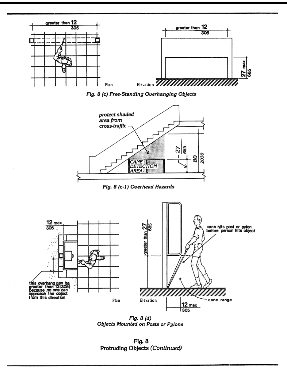
Pt. 36, App. A 28 CFR Ch. I (7-1-94 Edition)
514
4.4 Protruding Objects
23
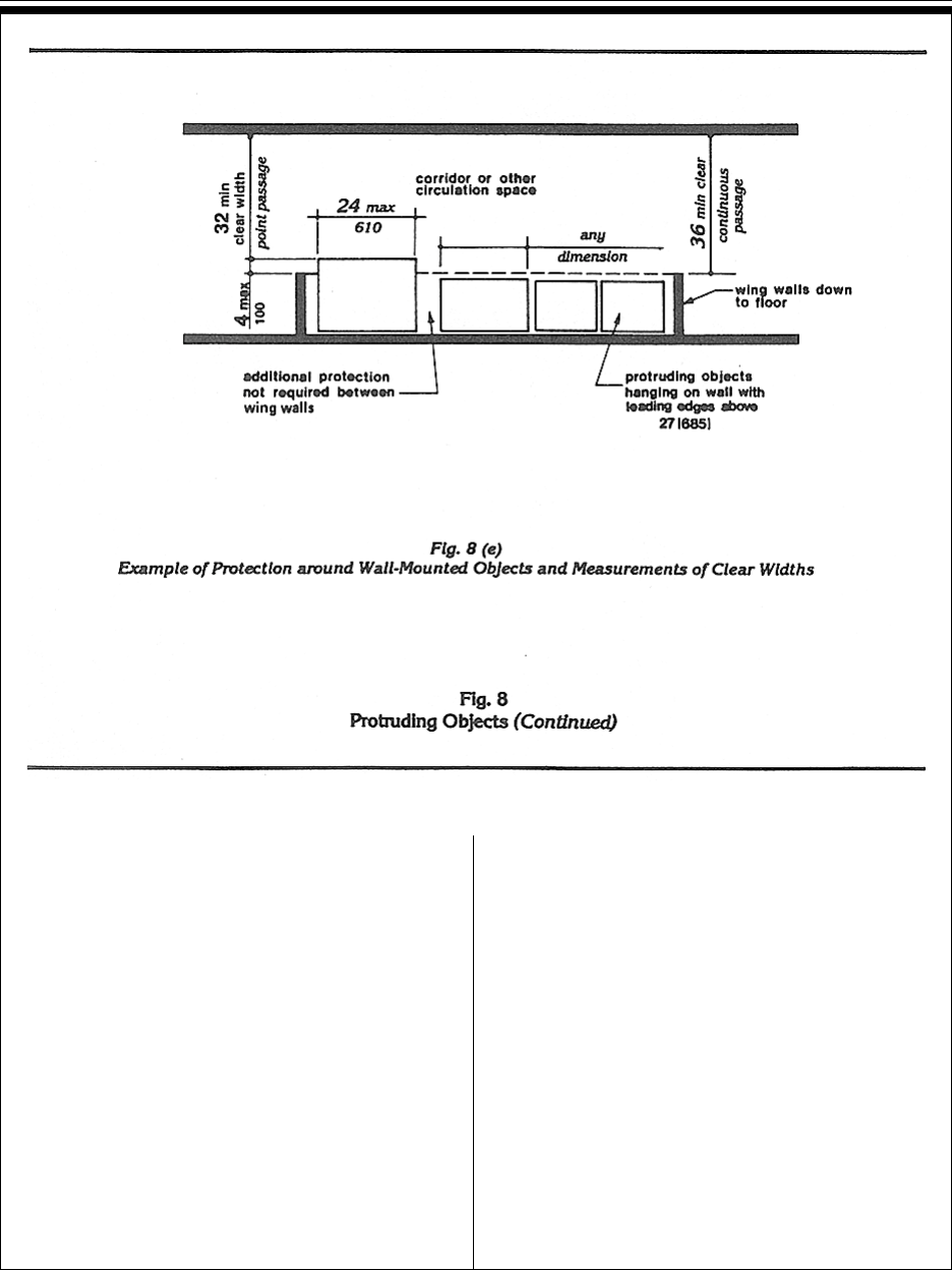
Pt. 36, App. ADepartment of Justice
515
shall be beveled with a slope no greater than
1:2 (see Fig. 7(d) ). Changes in level greater
than 1/2 in (13 mm) shall be accomplished by
means of a ramp that complies with 4.7 or 4.8.
4.5.3* Carpet. If carpet or carpet tile is used
on a ground or floor surface, then it shall be
securely attached; have a firm cushion, pad, or
backing, or no cushion or pad; and have a level
loop, textured loop, level cut pile, or level cut/
uncut pile texture. The maximum pile thick-
ness shall be 1/2 in (13 mm) (see Fig. 8(f)).
Exposed edges of carpet shall be fastened to
floor surfaces and have trim along the entire
length of the exposed edge. Carpet edge trim
shall comply with 4.5.2.
4.5.4 Gratings. If gratings are located in
walking surfaces, then they shall have spaces
no greater than 1/2 in (13 mm) wide in one
direction (see Fig. 8(g)). If gratings have elon-
gated openings, then they shall be placed so
that the long dimension is perpendicular to the
dominant direction of travel (see Fig. 8(h)).
4.6 Parking and Passenger Loading
Zones.
4.6.1 Minimum Number. Parking spaces
required to be accessible by 4.1 shall comply
with 4.6.2 through 4.6.5. Passenger loading
zones required to be accessible by 4.1 shall
comply with 4.6.5 and 4.6.6.
4.5 Ground and Floor Surfaces
24

Pt. 36, App. A 28 CFR Ch. I (7-1-94 Edition)
516
4.6.2 Location. Accessible parking spaces
serving a particular building shall be located on
the shortest accessible route of travel from
adjacent parking to an accessible entrance. In
parking facilities that do not serve a particular
building, accessible parking shall be located
on the shortest accessible route of travel to an
accessible pedestrian entrance of the parking
facility. In buildings with multiple accessible
entrances with adjacent parking, accessible
parking spaces shall be dispersed and located
closest to the accessible entrances.
4.6.3* Parking Spaces. Accessible parking
spaces shall be at least 96 in (2440 mm) wide.
Parking access aisles shall be part of an acces-
sible route to the building or facility entrance
and shall comply with 4.3. Two accessible
parking spaces may share a common access
aisle (see Fig. 9). Parked vehicle overhangs
shall not reduce the clear width of an acces-
sible route. Parking spaces and access aisles
shall be level with surface slopes not exceed-
ing 1:50 (2%) in all directions.
4.6.4* Signage. Accessible parking spaces
shall be designated as reserved by a sign
showing the symbol of accessibility (see
4.30.7). Spaces complying with 4.1.2(5)(b) shall
have an additional sign “Van-Accessible”
mounted below the symbol of accessibility.
Such signs shall be located so they cannot be
obscured by a vehicle parked in the space.
4.6.5* Vertical Clearance. Provide minimum
vertical clearance of 114 in (2895 mm) at
accessible passenger loading zones and along
at least one vehicle access route to such areas
from site entrance(s) and exit(s). At parking
spaces complying with 4.1.2(5)(b), provide
minimum vertical clearance of 98 in (2490
mm) at the parking space and along at least
one vehicle access route to such spaces from
site entrance(s) and exit(s).
4.6.6 Passenger Loading Zones. Passenger
loading zones shall provide an access aisle at
least 60 in (1525 mm) wide and 20 ft (240
in)(6100 mm) long adjacent and parallel to the
vehicle pull-up space (see Fig. 10). If there are
curbs between the access aisle and the vehicle
pull-up space, then a curb ramp complying with
4.7 shall be provided. Vehicle standing spaces
and access aisles shall be level with surface
4.6 Parking and Passenger Loading Zones
25

Pt. 36, App. ADepartment of Justice
517
slopes not exceeding 1:50 (2%) in all directions.
4.7 Curb Ramps.
4.7.1 Location. Curb ramps complying with
4.7 shall be provided wherever an accessible
route crosses a curb.
4.7.2 Slope. Slopes of curb ramps shall
comply with 4.8.2. The slope shall be measured
as shown in Fig. 11. Transitions from ramps to
walks, gutters, or streets shall be flush and
free of abrupt changes. Maximum slopes of
adjoining gutters, road surface immediately
adjacent to the curb ramp, or accessible route
shall not exceed 1:20.
4.7.3 Width. The minimum width of a curb
ramp shall be 36 in (915 mm), exclusive of
flared sides.
4.7.4 Surface. Surfaces of curb ramps shall
comply with 4.5.
4.7.5 Sides of Curb Ramps. If a curb ramp is
located where pedestrians must walk across
the ramp, or where it is not protected by
handrails or guardrails, it shall have flared
sides; the maximum slope of the flare shall be
1:10 (see Fig. 12(a)). Curb ramps with returned
curbs may be used where pedestrians would
not normally walk across the ramp (see Fig.
12(b)).
4.7.6 Built-up Curb Ramps. Built-up curb
ramps shall be located so that they do not
project into vehicular traffic lanes (see Fig. 13).
4.7.7 Detectable Warnings. A curb ramp shall
have a detectable warning complying with
4.29.2. The detectable warning shall extend the
full width and depth of the curb ramp.
4.7.8 Obstructions. Curb ramps shall be
located or protected to prevent their obstruction
by parked vehicles.
4.7.9 Location at Marked Crossings. Curb
ramps at marked crossings shall be wholly
contained within the markings, excluding any
flared sides (see Fig. 15).
4.7.10 Diagonal Curb Ramps. If diagonal (or
corner type) curb ramps have returned curbs or
other well-defined edges, such edges shall be
parallel to the direction of pedestrian flow. The
bottom of diagonal curb ramps shall have 48 in
(1220 mm) minimum clear space as shown in
Fig. 15(c) and (d). If diagonal curb ramps are
provided at marked crossings, the 48 in (1220
mm) clear space shall be within the markings
(see Fig. 15(c) and (d)). If diagonal curb ramps
have flared sides, they shall also have at least a
24 in (610 mm) long segment of straight curb
located on each side of the curb ramp and
within the marked crossing (see Fig. 15(c)).
4.7 Curb Ramps
26

Pt. 36, App. A 28 CFR Ch. I (7-1-94 Edition)
518
4.7.11 Islands. Any raised islands in cross-
ings shall be cut through level with the street or
have curb ramps at both sides and a level area
at least 48 in (1220 mm) long between the curb
ramps in the part of the island intersected by
the crossings (see Fig. 15(a) and (b)).
4.8 Ramps.
4.8.1* General. Any part of an accessible route
with a slope greater than 1:20 shall be consid-
ered a ramp and shall comply with 4.8.
4.8.2* Slope and Rise. The least possible
slope shall be used for any ramp. The maximum
slope of a ramp in new construction shall be
1:12. The maximum rise for any run shall be 30
in (760 mm) (see Fig. 16). Curb ramps and
ramps to be constructed on existing sites or in
existing buildings or facilities may have slopes
and rises as allowed in 4.1.6(3)(a) if space
limitations prohibit the use of a 1:12 slope or
less.
4.8 Ramps
27

Pt. 36, App. ADepartment of Justice
519
4.8 Ramps
28

Pt. 36, App. A 28 CFR Ch. I (7-1-94 Edition)
520
4.8.3 Clear Width. The minimum clear width
of a ramp shall be 36 in (915 mm).
4.8.4* Landings. Ramps shall have level
landings at bottom and top of each ramp and
each ramp run. Landings shall have the follow-
ing features:
(1) The landing shall be at least as wide as the
ramp run leading to it.
(2) The landing length shall be a minimum of
60 in (1525 mm) clear.
(3) If ramps change direction at landings, the
minimum landing size shall be 60 in by 60 in
(1525 mm by 1525 mm).
(4) If a doorway is located at a landing, then the
area in front of the doorway shall comply with
4.13.6.
4.8.5* Handrails. If a ramp run has a rise
greater than 6 in (150 mm) or a horizontal
projection greater than 72 in (1830 mm), then it
shall have handrails on both sides. Handrails
are not required on curb ramps or adjacent to
seating in assembly areas. Handrails shall
comply with 4.26 and shall have the following
features:
(1) Handrails shall be provided along both
sides of ramp segments. The inside handrail on
switchback or dogleg ramps shall always be
continuous.
(2) If handrails are not continuous, they shall
extend at least 12 in (305 mm) beyond the top
and bottom of the ramp segment and shall be
parallel with the floor or ground surface (see
Fig. 17).
(3) The clear space between the handrail and
the wall shall be 1 - 1/2 in (38 mm).
(4) Gripping surfaces shall be continuous.
(5) Top of handrail gripping surfaces shall be
mounted between 34 in and 38 in (865 mm and
965 mm) above ramp surfaces.
(6) Ends of handrails shall be either rounded
or returned smoothly to floor, wall, or post.
(7) Handrails shall not rotate within their
fittings.
4.8.6 Cross Slope and Surfaces. The cross
slope of ramp surfaces shall be no greater than
1:50. Ramp surfaces shall comply with 4.5.
4.8 Ramps
29

Pt. 36, App. ADepartment of Justice
521
4.8.7 Edge Protection. Ramps and landings
with drop-offs shall have curbs, walls, railings,
or projecting surfaces that prevent people from
slipping off the ramp. Curbs shall be a mini-
mum of 2 in (50 mm) high (see Fig. 17).
4.8.8 Outdoor Conditions. Outdoor ramps
and their approaches shall be designed so that
water will not accumulate on walking surfaces.
4.9 Stairs.
4.9.1* Minimum Number. Stairs required to
be accessible by 4.1 shall comply with 4.9.
4.9.2 Treads and Risers. On any given flight of
stairs, all steps shall have uniform riser heights
and uniform tread widths. Stair treads shall be
no less than 11 in (280 mm) wide, measured
from riser to riser (see Fig. 18(a)). Open risers
are not permitted.
4.9.3 Nosings. The undersides of nosings shall
not be abrupt. The radius of curvature at the
leading edge of the tread shall be no greater
than 1/2 in (13 mm). Risers shall be sloped or
the underside of the nosing shall have an angle
not less than 60 degrees from the horizontal.
Nosings shall project no more than 1-1/2 in (38
mm) (see Fig. 18).
4.9.4 Handrails. Stairways shall have hand-
rails at both sides of all stairs. Handrails shall
comply with 4.26 and shall have the following
features:
(1) Handrails shall be continuous along both
sides of stairs. The inside handrail on
switchback or dogleg stairs shall always be
continuous (see Fig. 19(a) and (b)).
(2) If handrails are not continuous, they shall
extend at least 12 in (305 mm) beyond the top
riser and at least 12 in (305 mm) plus the width
of one tread beyond the bottom riser. At the top,
the extension shall be parallel with the floor or
ground surface. At the bottom, the handrail
shall continue to slope for a distance of the
width of one tread from the bottom riser; the
remainder of the extension shall be horizontal
(see Fig. 19(c) and (d)). Handrail extensions
shall comply with 4.4.
(3) The clear space between handrails and
wall shall be 1-1/2 in (38 mm).
(4) Gripping surfaces shall be uninterrupted
by newel posts, other construction elements, or
obstructions.
(5) Top of handrail gripping surface shall be
mounted between 34 in and 38 in (865 mm and
965 mm) above stair nosings.
(6) Ends of handrails shall be either rounded
or returned smoothly to floor, wall or post.
(7) Handrails shall not rotate within their
fittings.
4.9.5 Detectable Warnings at Stairs.
(Reserved).
4.9.6 Outdoor Conditions. Outdoor stairs and
their approaches shall be designed so that
water will not accumulate on walking surfaces.
4.10 Elevators.
4.10.1 General. Accessible elevators shall be
on an accessible route and shall comply with
4.10 and with the ASME A17.1-1990, Safety
Code for Elevators and Escalators. Freight
elevators shall not be considered as meeting
the requirements of this section unless the
only elevators provided are used as combina-
tion passenger and freight elevators for the
public and employees.
4.10.2 Automatic Operation. Elevator opera-
tion shall be automatic. Each car shall be
equipped with a self-leveling feature that will
automatically bring the car to floor landings
within a tolerance of 1/2 in (13 mm) under rated
loading to zero loading conditions. This
self-leveling feature shall be automatic and
independent of the operating device and shall
correct the overtravel or undertravel.
4.10.3 Hall Call Buttons. Call buttons in
elevator lobbies and halls shall be centered at
42 in (1065 mm) above the floor. Such call
buttons shall have visual signals to indicate
when each call is registered and when each call
is answered. Call buttons shall be a minimum
of 3/4 in (19 mm) in the smallest dimension.
The button designating the up direction shall
be on top. (See Fig. 20.) Buttons shall be raised
or flush. Objects mounted beneath hall call
buttons shall not project into the elevator
lobby more than 4 in (100 mm).
4.9 Stairs
30

Pt. 36, App. A 28 CFR Ch. I (7-1-94 Edition)
522
4.10 Elevators
31

Pt. 36, App. ADepartment of Justice
523
4.10 Elevators
32

Pt. 36, App. A 28 CFR Ch. I (7-1-94 Edition)
524
4.10.4 Hall Lanterns. A visible and audible
signal shall be provided at each hoistway
entrance to indicate which car is answering a
call. Audible signals shall sound once for the up
direction and twice for the down direction or
shall have verbal annunciators that say “up” or
“down.” Visible signals shall have the following
features:
(1) Hall lantern fixtures shall be mounted so
that their centerline is at least 72 in (1830 mm)
above the lobby floor. (See Fig. 20.)
(2) Visual elements shall be at least 2-1/2 in
(64 mm) in the smallest dimension.
(3) Signals shall be visible from the vicinity of
the hall call button (see Fig. 20). In-car lanterns
located in cars, visible from the vicinity of hall
call buttons, and conforming to the above
requirements, shall be acceptable.
4.10.5 Raised and Braille Characters on
Hoistway Entrances. All elevator hoistway
entrances shall have raised and Braille floor
designations provided on both jambs. The
centerline of the characters shall be 60 in (1525
mm) above finish floor. Such characters shall
be 2 in (50 mm) high and shall comply with
4.30.4. Permanently applied plates are accept-
able if they are permanently fixed to the jambs.
(See Fig. 20).
4.10.6* Door Protective and Reopening
Device. Elevator doors shall open and close
automatically. They shall be provided with a
reopening device that will stop and reopen a car
door and hoistway door automatically if the
door becomes obstructed by an object or
person. The device shall be capable of complet-
ing these operations without requiring contact
for an obstruction passing through the opening
at heights of 5 in and 29 in (125 mm and 735
mm) above finish floor (see Fig. 20). Door
reopening devices shall remain effective for at
least 20 seconds. After such an interval, doors
may close in accordance with the requirements
of ASME A17.1-1990.
4.10.7* Door and Signal Timing for Hall
Calls. The minimum acceptable time from
notification that a car is answering a call until
the doors of that car start to close
shall be calculated from the following equation:
T = D/(1.5 ft/s) or T = D/(445 mm/s)
where T total time in seconds and D distance
(in feet or millimeters) from a point in the lobby
or corridor 60 in (1525 mm) directly in front of
the farthest call button controlling that car to
the centerline of its hoistway door (see Fig. 21).
For cars with in-car lanterns, T begins when the
lantern is visible from the vicinity of hall call
buttons and an audible signal is sounded. The
minimum acceptable notification time shall be
5 seconds.
4.10.8 Door Delay for Car Calls. The mini-
mum time for elevator doors to remain fully
open in response to a car call shall be 3 sec-
onds.
4.10.9 Floor Plan of Elevator Cars. The floor
area of elevator cars shall provide space for
wheelchair users to enter the car, maneuver
4.10 Elevators
33

Pt. 36, App. ADepartment of Justice
525
within reach of controls, and exit from the car.
Acceptable door opening and inside dimensions
shall be as shown in Fig. 22. The clearance
between the car platform sill and the edge of
any hoistway landing shall be no greater than
1-1/4 in (32 mm).
4.10.10 Floor Surfaces. Floor surfaces shall
comply with 4.5.
4.10.11 Illumination Levels. The level of
illumination at the car controls, platform, and
car threshold and landing sill shall be at least 5
footcandles (53.8 lux).
4.10.12* Car Controls. Elevator control
panels shall have the following features:
(1) Buttons. All control buttons shall be at
least 3/4 in (19 mm) in their smallest dimen-
sion. They shall be raised or flush.
(2) Tactile, Braille, and Visual Control Indica-
tors. All control buttons shall be designated by
Braille and by raised standard alphabet charac-
ters for letters, arabic characters for numerals,
or standard symbols as shown in Fig. 23(a), and
as required in ASME A17.1-1990. Raised and
Braille characters and symbols shall comply
with 4.30. The call button for the main entry
floor shall be designated by a raised star at the
left of the floor designation (see Fig. 23(a)). All
raised designations for control buttons shall be
placed immediately to the left of the button to
which they apply. Applied plates, permanently
attached, are an acceptable means to provide
raised control designations. Floor buttons
shall be provided with visual indicators to
show when each call is registered. The visual
indicators shall be extinguished when each
call is answered.
(3) Height. All floor buttons shall be no
higher than 54 in (1370 mm) above the finish
floor for side approach and 48 in (1220 mm)
for front approach. Emergency controls,
including the emergency alarm and emergency
stop, shall be grouped at the bottom of the
panel and shall have their centerlines no less
than 35 in (890 mm) above the finish floor (see
Fig. 23(a) and (b)).
4.10.12 Car Controls
34

Pt. 36, App. A 28 CFR Ch. I (7-1-94 Edition)
526
(4) Location. Controls shall be located on a
front wall if cars have center opening doors,
and at the side wall or at the front wall next to
the door if cars have side opening doors (see
Fig. 23(c) and (d)).
4.10.13* Car Position Indicators. In
elevator cars, a visual car position indicator
shall be provided above the car control panel
or over the door to show the position of the
elevator in the hoistway. As the car passes or
stops at a floor served by the elevators, the
corresponding numerals shall illuminate,
and an audible signal shall sound. Numerals
shall be a minimum of 1/2 in (13 mm) high.
The audible signal shall be no less than 20
decibels with a frequency no higher than 1500
Hz. An automatic verbal announcement of the
floor number at which a car stops or which a
car passes may be substituted for the audible
signal.
4.10.14* Emergency Communications.
If provided, emergency two-way communica-
tion systems between the elevator and a point
outside the hoistway shall comply with ASME
4.10.13 Car Position Indicators
35

Pt. 36, App. ADepartment of Justice
527
A17.1-1990. The highest operable part of a
two-way communication system shall be a
maximum of 48 in (1220 mm) from the floor of
the car. It shall be identified by a raised symbol
and lettering complying with 4.30 and located
adjacent to the device. If the system uses a
handset then the length of the cord from the
panel to the handset shall be at least 29 in (735
mm). If the system is located in a closed
compartment the compartment door hardware
shall conform to 4.27, Controls and Operating
Mechanisms. The emergency intercommunica-
tion system shall not require voice communi-
cation.
4.11 Platform Lifts (Wheelchair
Lifts).
4.11.1 Location. Platform lifts (wheelchair
lifts) permitted by 4.1 shall comply with the
requirements of 4.11.
4.11.2* Other Requirements. If platform lifts
(wheelchair lifts) are used, they shall comply
with 4.2.4, 4.5, 4.27, and ASME A17.1 Safety
Code for Elevators and Escalators, Section
XX, 1990.
4.11.3 Entrance. If platform lifts are used
then they shall facilitate unassisted entry,
operation, and exit from the lift in compliance
with 4.11.2.
4.12 Windows.
4.12.1* General. (Reserved).
4.12.2* Window Hardware. (Reserved).
4.13 Doors.
4.13.1 General. Doors required to be acces-
sible by 4.1 shall comply with the require-
ments of 4.13.
4.13.2 Revolving Doors and Turnstiles.
Revolving doors or turnstiles shall not be the
only means of passage at an accessible en-
trance or along an accessible route. An acces-
sible gate or door shall be provided adjacent
to the turnstile or revolving door and shall be
so designed as to facilitate the same use
pattern.
4.13.3 Gates. Gates, including ticket gates,
shall meet all applicable specifications of 4.13.
4.13.4 Double-Leaf Doorways. If doorways
have two independently operated door leaves,
then at least one leaf shall meet the specifica-
tions in 4.13.5 and 4.13.6. That leaf shall be an
active leaf.
4.13.5 Clear Width. Doorways shall have a
minimum clear opening of 32 in (815 mm) with
the door open 90 degrees, measured between
the face of the door and the opposite stop (see
Fig. 24(a), (b), (c), and (d)). Openings more than
24 in (610 mm) in depth shall comply with
4.2.1 and 4.3.3 (see Fig. 24(e)).
EXCEPTION: Doors not requiring full user
passage, such as shallow closets, may have
the clear opening reduced to 20 in (510 mm)
minimum.
4.13.6 Maneuvering Clearances at Doors.
Minimum maneuvering clearances at doors
that are not automatic or power-assisted shall
be as shown in Fig. 25. The floor or ground
area within the required clearances shall be
level and clear.
EXCEPTION: Entry doors to acute care hospi-
tal bedrooms for in-patients shall be exempted
from the requirement for space at the latch
side of the door (see dimension “x” in Fig. 25) if
the door is at least 44 in (1120 mm) wide.
4.13.7 Two Doors in Series. The minimum
space between two hinged or pivoted doors in
series shall be 48 in (1220 mm) plus the width
of any door swinging into the space. Doors in
series shall swing either in the same direction
or away from the space between the doors (see
Fig. 26).
4.13.8* Thresholds at Doorways. Thresholds
at doorways shall not exceed 3/4 in (19 mm) in
height for exterior sliding doors or 1/2 in (13
mm) for other types of doors. Raised thresh-
olds and floor level changes at accessible
doorways shall be beveled with a slope no
greater than 1:2 (see 4.5.2).
4.13.9* Door Hardware. Handles, pulls,
latches, locks, and other operating devices on
accessible doors shall have a shape that is
4.11 Platform Lifts (Wheelchair Lifts)
36

Pt. 36, App. A 28 CFR Ch. I (7-1-94 Edition)
528
easy to grasp with one hand and does not
require tight grasping, tight pinching, or
twisting of the wrist to operate. Lever-operated
mechanisms, push-type mechanisms, and
U-shaped handles are acceptable designs.
When sliding doors are fully open, operating
hardware shall be exposed and usable from
both sides. Hardware required for accessible
door passage shall be mounted no higher
than 48 in (1220 mm) above finished floor.
4.13.10* Door Closers. If a door has a closer,
then the sweep period of the closer shall be
adjusted so that from an open position of 70
degrees, the door will take at least 3 seconds
to move to a point 3 in (75 mm) from the latch,
measured to the leading edge of the door.
4.13.11* Door Opening Force. The maximum
force for pushing or pulling open a door shall
be as follows:
(1) Fire doors shall have the minimum
opening force allowable by the appropriate
administrative authority.
(2) Other doors.
(a) exterior hinged doors: (Reserved).
(b) interior hinged doors: 5 lbf (22.2N)
(c) sliding or folding doors: 5 lbf (22.2N)
These forces do not apply to the force required
to retract latch bolts or disengage other devices
that may hold the door in a closed position.
4.13 Doors
37

Pt. 36, App. ADepartment of Justice
529
4.13 Doors
38

Pt. 36, App. A 28 CFR Ch. I (7-1-94 Edition)
530
4.13 Doors
39

Pt. 36, App. ADepartment of Justice
531
4.13.12* Automatic Doors and Power-
Assisted Doors. If an automatic door is used,
then it shall comply with ANSI/BHMA
A156.10-1985. Slowly opening, low-powered,
automatic doors shall comply with ANSI
A156.19-1984. Such doors shall not open to
back check faster than 3 seconds and shall
require no more than 15 lbf (66.6N) to stop
door movement. If a power-assisted door is
used, its door-opening force shall comply with
4.13.11 and its closing shall conform to the
requirements in ANSI A156.19-1984.
4.14 Entrances.
4.14.1 Minimum Number. Entrances re-
quired to be accessible by 4.1 shall be part of
an accessible route complying with 4.3. Such
entrances shall be connected by an accessible
route to public transportation stops, to acces-
sible parking and passenger loading zones,
and to public streets or sidewalks if available
(see 4.3.2(1)). They shall also be connected by
an accessible route to all accessible spaces or
elements within the building or facility.
4.14.2 Service Entrances. A service entrance
shall not be the sole accessible entrance
unless it is the only entrance to a building or
facility (for example, in a factory or garage).
4.15 Drinking Fountains and Water
Coolers.
4.15.1 Minimum Number. Drinking foun-
tains or water coolers required to be accessible
by 4.1 shall comply with 4.15.
4.15.2* Spout Height. Spouts shall be no
higher than 36 in (915 mm), measured from
the floor or ground surfaces to the spout outlet
(see Fig. 27(a)).
4.15.3 Spout Location. The spouts of
drinking fountains and water coolers shall be
at the front of the unit and shall direct the
water flow in a trajectory that is parallel or
nearly parallel to the front of the unit. The
spout shall provide a flow of water at least 4 in
(100 mm) high so as to allow the insertion of a
cup or glass under the flow of water. On an
accessible drinking fountain with a round or
oval bowl, the spout must be positioned so the
flow of water is within 3 in (75 mm) of the front
edge of the fountain.
4.15.4 Controls. Controls shall comply with
4.27.4. Unit controls shall be front mounted or
side mounted near the front edge.
4.15.5 Clearances.
(1) Wall- and post-mounted cantilevered units
shall have a clear knee space between the
bottom of the apron and the floor or ground at
least 27 in (685 mm) high, 30 in (760 mm) wide,
and 17 in to 19 in (430 mm to 485 mm) deep
(see Fig. 27(a) and (b)). Such units shall also
have a minimum clear floor space 30 in by 48
in (760 mm by 1220 mm) to allow a person in a
wheelchair to approach the unit facing forward.
(2) Free-standing or built-in units not having
a clear space under them shall have a clear
floor space at least 30 in by 48 in (760 mm by
1220 mm) that allows a person in a wheelchair
to make a parallel approach to the unit (see Fig.
27(c) and (d)). This clear floor space shall
comply with 4.2.4.
4.16 Water Closets.
4.16.1 General. Accessible water closets shall
comply with 4.16.
4.16.2 Clear Floor Space. Clear floor space
for water closets not in stalls shall comply with
Fig. 28. Clear floor space may be arranged to
allow either a left-handed or right-handed
approach.
4.16.3* Height. The height of water closets
shall be 17 in to 19 in (430 mm to 485 mm),
measured to the top of the toilet seat (see Fig.
29(b)). Seats shall not be sprung to return to a
lifted position.
4.16.4* Grab Bars. Grab bars for water
closets not located in stalls shall comply with
4.26 and Fig. 29. The grab bar behind the water
closet shall be 36 in (915 mm) minimum.
4.16.5* Flush Controls. Flush controls shall
be hand operated or automatic and shall
comply with 4.27.4. Controls for flush valves
4.14 Entrances
40

Pt. 36, App. A 28 CFR Ch. I (7-1-94 Edition)
532
shall be mounted on the wide side of toilet
areas no more than 44 in (1120 mm) above the
floor.
4.16.6 Dispensers. Toilet paper dispensers
shall be installed within reach, as shown in
Fig. 29(b). Dispensers that control delivery, or
that do not permit continuous paper flow,
shall not be used.
4.17 Toilet Stalls.
4.17.1 Location. Accessible toilet stalls shall
be on an accessible route and shall meet the
requirements of 4.17.
4.17.2 Water Closets. Water closets in
accessible stalls shall comply with 4.16.
4.17 Toilet Stalls
41
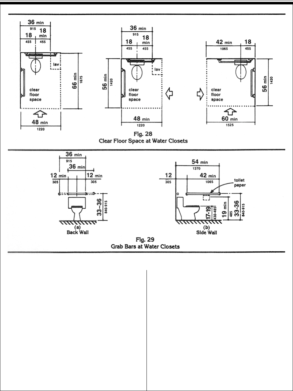
Pt. 36, App. ADepartment of Justice
533
4.17.3* Size and Arrangement. The size and
arrangement of the standard toilet stall shall
comply with Fig. 30(a), Standard Stall. Stan-
dard toilet stalls with a minimum depth of 56
in (1420 mm) (see Fig. 30(a)) shall have
wall-mounted water closets. If the depth of a
standard toilet stall is increased at least 3 in
(75 mm), then a floor-mounted water closet
may be used. Arrangements shown for stan-
dard toilet stalls may be reversed to allow
either a left- or right-hand approach. Additional
stalls shall be provided in conformance with
4.22.4.
EXCEPTION: In instances of alteration work
where provision of a standard stall (Fig. 30(a))
is technically infeasible or where plumbing
code requirements prevent combining existing
stalls to provide space, either alternate stall
(Fig. 30(b)) may be provided in lieu of the
standard stall.
4.17.4 Toe Clearances. In standard stalls, the
front partition and at least one side partition
shall provide a toe clearance of at least 9 in
(230 mm) above the floor. If the depth of the
stall is greater than 60 in (1525 mm), then the
toe clearance is not required.
4.17.5* Doors. Toilet stall doors, including
door hardware, shall comply with 4.13. If toilet
stall approach is from the latch side of the stall
door, clearance between the door side of the
4.17 Toilet Stalls
42
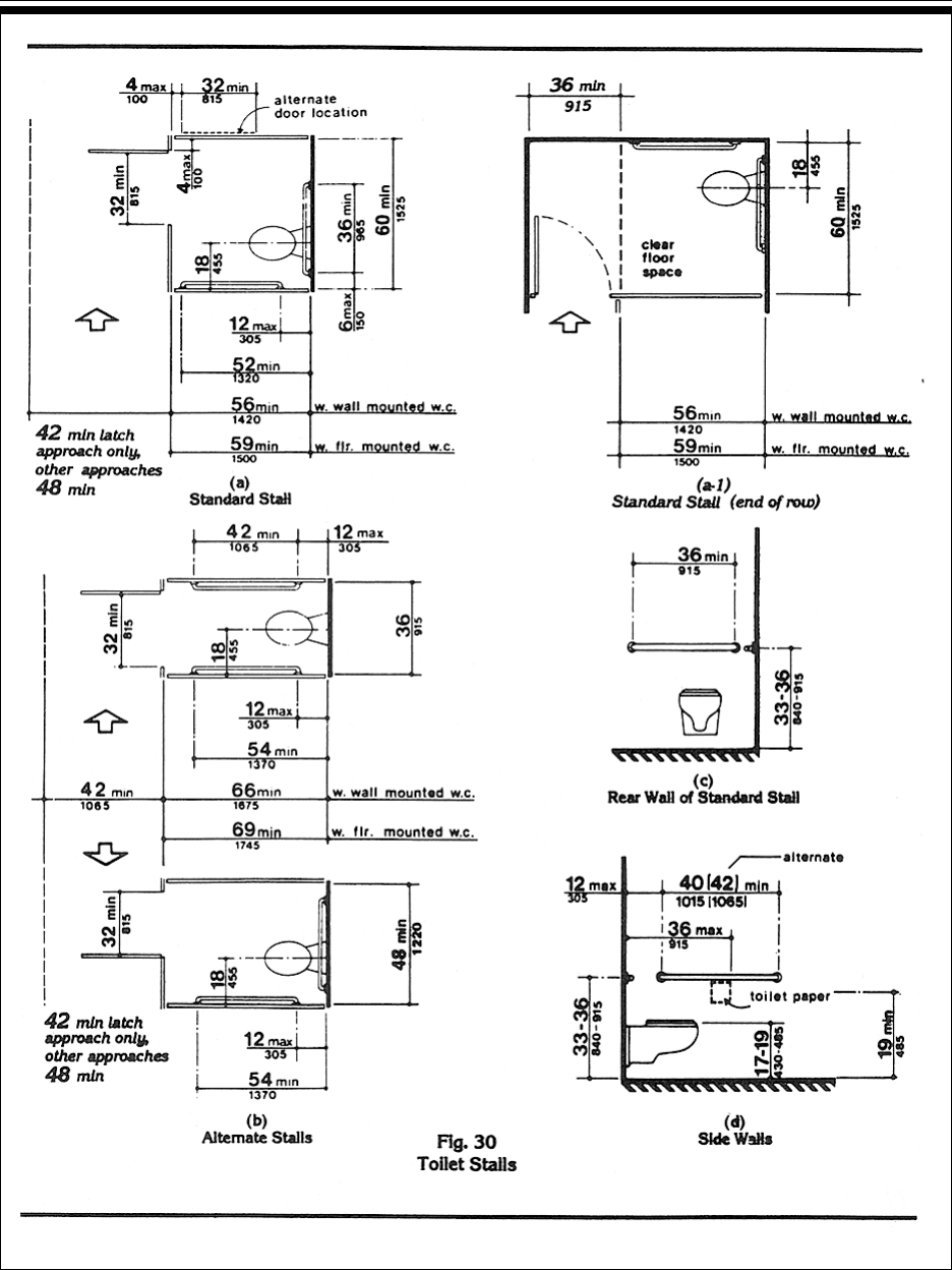
Pt. 36, App. A 28 CFR Ch. I (7-1-94 Edition)
534
4.17 Toilet Stalls
43

Pt. 36, App. ADepartment of Justice
535
stall and any obstruction may be reduced to a
minimum of 42 in (1065 mm) (Fig. 30).
4.17.6 Grab Bars. Grab bars complying with
the length and positioning shown in Fig. 30(a),
(b), (c), and (d) shall be provided. Grab bars may
be mounted with any desired method as long as
they have a gripping surface at the locations
shown and do not obstruct the required clear
floor area. Grab bars shall comply with 4.26.
4.18 Urinals.
4.18.1 General. Accessible urinals shall
comply with 4.18.
4.18.2 Height. Urinals shall be stall-type or
wall-hung with an elongated rim at a maximum
of 17 in (430 mm) above the finish floor.
4.18.3 Clear Floor Space. A clear floor space
30 in by 48 in (760 mm by 1220 mm) shall be
provided in front of urinals to allow forward
approach. This clear space shall adjoin or
overlap an accessible route and shall comply
with 4.2.4. Urinal shields that do not extend
beyond the front edge of the urinal rim may be
provided with 29 in (735 mm) clearance be-
tween them.
4.18.4 Flush Controls. Flush controls shall be
hand operated or automatic, and shall comply
with 4.27.4, and shall be mounted no more than
44 in (1120 mm) above the finish floor.
4.19 Lavatories and Mirrors.
4.19.1 General. The requirements of 4.19 shall
apply to lavatory fixtures, vanities, and built-in
lavatories.
4.19.2 Height and Clearances. Lavatories
shall be mounted with the rim or counter
surface no higher than 34 in (865 mm) above
the finish floor. Provide a clearance of at least
29 in (735 mm) above the finish floor to the
bottom of the apron. Knee and toe clearance
shall comply with Fig. 31.
4.19.3 Clear Floor Space. A clear floor space
30 in by 48 in (760 mm by 1220 mm) complying
with 4.2.4 shall be provided in front of a lavatory
to allow forward approach. Such clear floor
space shall adjoin or overlap an accessible
route and shall extend a maximum of 19 in
(485 mm) underneath the lavatory (see Fig. 32).
4.19.4 Exposed Pipes and Surfaces. Hot
water and drain pipes under lavatories shall be
insulated or otherwise configured to protect
against contact. There shall be no sharp or
abrasive surfaces under lavatories.
4.19.5 Faucets. Faucets shall comply with
4.27.4. Lever-operated, push-type, and elec-
tronically controlled mechanisms are ex-
amples of acceptable designs. If self-closing
4.19 Lavatories and Mirrors
44

Pt. 36, App. A 28 CFR Ch. I (7-1-94 Edition)
536
valves are used the faucet shall remain open
for at least 10 seconds.
4.19.6* Mirrors. Mirrors shall be mounted
with the bottom edge of the reflecting surface
no higher than 40 in (1015 mm) above the
finish floor (see Fig. 31).
4.20 Bathtubs.
4.20.1 General. Accessible bathtubs shall
comply with 4.20.
4.20.2 Floor Space. Clear floor space in front
of bathtubs shall be as shown in Fig. 33.
4.20.3 Seat. An in-tub seat or a seat at the
head end of the tub shall be provided as shown
in Fig. 33 and 34. The structural strength of
seats and their attachments shall comply with
4.26.3. Seats shall be mounted securely and
shall not slip during use.
4.20.4 Grab Bars. Grab bars complying with
4.26 shall be provided as shown in Fig. 33 and
34.
4.20.5 Controls. Faucets and other controls
complying with 4.27.4 shall be located as
shown in Fig. 34.
4.20.6 Shower Unit. A shower spray unit
with a hose at least 60 in (1525 mm) long that
can be used both as a fixed shower head and
as a hand-held shower shall be provided.
4.20.7 Bathtub Enclosures. If provided,
enclosures for bathtubs shall not obstruct
controls or transfer from wheelchairs onto
bathtub seats or into tubs. Enclosures on
bathtubs shall not have tracks mounted on
their rims.
4.21 Shower Stalls.
4.21.1* General. Accessible shower stalls
shall comply with 4.21.
4.21.2 Size and Clearances. Except as
specified in 9.1.2, shower stall size and clear
floor space shall comply with Fig. 35(a) or (b).
The shower stall in Fig. 35(a) shall be 36 in by
36 in (915 mm by 915 mm). Shower stalls
required by 9.1.2 shall comply with Fig. 57(a)
or (b). The shower stall in Fig. 35(b) will fit into
the space required for a bathtub.
4.21.3 Seat. A seat shall be provided in
shower stalls 36 in by 36 in (915 mm by 915
mm) and shall be as shown in Fig. 36. The seat
shall be mounted 17 in to 19 in (430 mm to
485 mm) from the bathroom floor and shall
extend the full depth of the stall. In a 36 in by
36 in (915 mm by 915 mm) shower stall, the
seat shall be on the wall opposite the controls.
Where a fixed seat is provided in a 30 in by 60
in minimum (760 mm by 1525 mm) shower
stall, it shall be a folding type and shall be
mounted on the wall adjacent to the controls
as shown in Fig. 57. The structural strength of
seats and their attachments shall comply with
4.26.3.
4.21.4 Grab Bars. Grab bars complying with
4.26 shall be provided as shown in Fig. 37.
4.21.5 Controls. Faucets and other controls
complying with 4.27.4 shall be located as
shown in Fig. 37. In shower stalls 36 in by 36
in (915 mm by 915 mm), all controls, faucets,
and the shower unit shall be mounted on the
side wall opposite the seat.
4.21.6 Shower Unit. A shower spray unit
with a hose at least 60 in (1525 mm) long that
can be used both as a fixed shower head and
as a hand-held shower shall be provided.
EXCEPTION: In unmonitored facilities where
vandalism is a consideration, a fixed shower
head mounted at 48 in (1220 mm) above the
shower floor may be used in lieu of a
hand-held shower head.
4.21.7 Curbs. If provided, curbs in shower
stalls 36 in by 36 in (915 mm by 915 mm) shall
be no higher than 1/2 in (13 mm). Shower
stalls that are 30 in by 60 in (760 mm by 1525
mm) minimum shall not have curbs.
4.21.8 Shower Enclosures. If provided,
enclosures for shower stalls shall not obstruct
controls or obstruct transfer from wheelchairs
onto shower seats.
4.22 Toilet Rooms.
4.22.1 Minimum Number. Toilet facilities
required to be accessible by 4.1 shall comply
4.20 Bathtubs
45

Pt. 36, App. ADepartment of Justice
537
4.21 Shower Stalls
46

Pt. 36, App. A 28 CFR Ch. I (7-1-94 Edition)
538
with 4.22. Accessible toilet rooms shall be on
an accessible route.
4.22.2 Doors. All doors to accessible toilet
rooms shall comply with 4.13. Doors shall not
swing into the clear floor space required for
any fixture.
4.22.3* Clear Floor Space. The accessible
fixtures and controls required in 4.22.4, 4.22.5,
4.22.6, and 4.22.7 shall be on an accessible
route. An unobstructed turning space comply-
ing with 4.2.3 shall be provided within an
accessible toilet room. The clear floor space at
fixtures and controls, the accessible route, and
the turning space may overlap.
4.22.4 Water Closets. If toilet stalls are
provided, then at least one shall be a standard
toilet stall complying with 4.17; where 6 or
more stalls are provided, in addition to the
stall complying with 4.17.3, at least one stall
36 in (915 mm) wide with an outward swing-
ing, self-closing door and parallel grab bars
complying with Fig. 30(d) and 4.26 shall be
provided. Water closets in such stalls shall
comply with 4.16. If water closets are not in
stalls, then at least one shall comply with
4.16.
4.22.5 Urinals. If urinals are provided, then
at least one shall comply with 4.18.
4.22.6 Lavatories and Mirrors. If lavatories
and mirrors are provided, then at least one of
each shall comply with 4.19.
4.22.7 Controls and Dispensers.
If controls, dispensers, receptacles, or other
4.22 Toilet Rooms
47

Pt. 36, App. ADepartment of Justice
539
equipment are provided, then at least one of
each shall be on an accessible route and shall
comply with 4.27.
4.23 Bathrooms, Bathing Facilities,
and Shower Rooms.
4.23.1 Minimum Number. Bathrooms,
bathing facilities, or shower rooms required to
be accessible by 4.1 shall comply with 4.23
and shall be on an accessible route.
4.23.2 Doors. Doors to accessible bathrooms
shall comply with 4.13. Doors shall not swing
into the floor space required for any fixture.
4.23.3* Clear Floor Space. The accessible
fixtures and controls required in 4.23.4, 4.23.5,
4.23.6, 4.23.7, 4.23.8, and 4.23.9 shall be on an
accessible route. An unobstructed turning
4.23 Bathrooms, Bathing Facilities, and Shower Rooms
48

Pt. 36, App. A 28 CFR Ch. I (7-1-94 Edition)
540
space complying with 4.2.3 shall be provided
within an accessible bathroom. The clear floor
spaces at fixtures and controls, the accessible
route, and the turning space may overlap.
4.23.4 Water Closets. If toilet stalls are
provided, then at least one shall be a standard
toilet stall complying with 4.17; where 6 or
more stalls are provided, in addition to the
stall complying with 4.17.3, at least one stall
36 in (915 mm) wide with an outward swing-
ing, self-closing door and parallel grab bars
complying with Fig. 30(d) and 4.26 shall be
provided. Water closets in such stalls shall
comply with 4.16. If water closets are not in
stalls, then at least one shall comply with 4.16.
4.23.5 Urinals. If urinals are provided, then at
least one shall comply with 4.18.
4.23.6 Lavatories and Mirrors. If lavatories
and mirrors are provided, then at least one of
each shall comply with 4.19.
4.23.7 Controls and Dispensers. If controls,
dispensers, receptacles, or other equipment
are provided, then at least one of each shall be
on an accessible route and shall comply with
4.27.
4.23.8 Bathing and Shower Facilities. If
tubs or showers are provided, then at least one
accessible tub that complies with 4.20 or at
least one accessible shower that complies with
4.21 shall be provided.
4.23.9* Medicine Cabinets. If medicine
cabinets are provided, at least one shall be
located with a usable shelf no higher than 44
in (1120 mm) above the floor space. The floor
space shall comply with 4.2.4.
4.24 Sinks.
4.24.1 General. Sinks required to be acces-
sible by 4.1 shall comply with 4.24.
4.24.2 Height. Sinks shall be mounted with
the counter or rim no higher than 34 in (865
mm) above the finish floor.
4.24.3 Knee Clearance. Knee clearance that
is at least 27 in (685 mm) high, 30 in (760 mm)
wide, and 19 in (485 mm) deep shall be pro-
vided underneath sinks.
4.24.4 Depth. Each sink shall be a maximum
of 6-1/2 in (165 mm) deep.
4.24.5 Clear Floor Space. A clear floor space
at least 30 in by 48 in (760 mm by 1220 mm)
complying with 4.2.4 shall be provided in front
of a sink to allow forward approach. The clear
floor space shall be on an accessible route and
shall extend a maximum of 19 in (485 mm)
underneath the sink (see Fig. 32).
4.24.6 Exposed Pipes and Surfaces. Hot
water and drain pipes exposed under sinks
shall be insulated or otherwise configured so
as to protect against contact. There shall be
no sharp or abrasive surfaces under sinks.
4.24.7 Faucets. Faucets shall comply with
4.27.4. Lever-operated, push-type, touch-type,
or electronically controlled mechanisms are
acceptable designs.
4.25 Storage.
4.25.1 General. Fixed storage facilities such
as cabinets, shelves, closets, and drawers
required to be accessible by 4.1 shall comply
with 4.25.
4.25.2 Clear Floor Space. A clear floor space
at least 30 in by 48 in (760 mm by 1220 mm)
complying with 4.2.4 that allows either a
forward or parallel approach by a person using
a wheelchair shall be provided at accessible
storage facilities.
4.25.3 Height. Accessible storage spaces
shall be within at least one of the reach ranges
specified in 4.2.5 and 4.2.6 (see Fig. 5 and Fig
6). Clothes rods or shelves shall be a maxi-
mum of 54 in (1370 mm) above the finish floor
for a side approach. Where the distance from
the wheelchair to the clothes rod or shelf
exceeds 10 in (255 mm) (as in closets without
accessible doors) the height and depth to the
rod or shelf shall comply with Fig. 38(a) and
Fig. 38(b).
4.25.4 Hardware. Hardware for accessible
storage facilities shall comply with 4.27.4.
Touch latches and U-shaped pulls are accept-
able.
4.24 Sinks
49
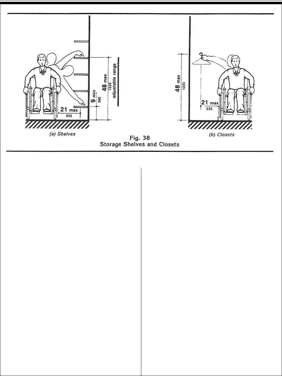
Pt. 36, App. ADepartment of Justice
541
4.26 Handrails, Grab Bars, and Tub
and Shower Seats.
4.26.1* General. All handrails, grab bars, and
tub and shower seats required to be accessible
by 4.1, 4.8, 4.9, 4.16, 4.17, 4.20 or 4.21 shall
comply with 4.26.
4.26.2* Size and Spacing of Grab Bars and
Handrails. The diameter or width of the
gripping surfaces of a handrail or grab bar shall
be 1-1/4 in to 1-1/2 in (32 mm to 38 mm), or the
shape shall provide an equivalent gripping
surface. If handrails or grab bars are mounted
adjacent to a wall, the space between the wall
and the grab bar shall be 1-1/2 in (38 mm) (see
Fig. 39(a), (b), (c), and (e)). Handrails may be
located in a recess if the recess is a maximum
of 3 in (75 mm) deep and extends at least 18 in
(455 mm) above the top of the rail (see Fig.
39(d)).
4.26.3 Structural Strength. The structural
strength of grab bars, tub and shower seats,
fasteners, and mounting devices shall meet the
following specification:
(1) Bending stress in a grab bar or seat
induced by the maximum bending moment
from the application of 250 lbf (1112N) shall be
less than the allowable stress for the material
of the grab bar or seat.
(2) Shear stress induced in a grab bar or seat
by the application of 250 lbf (1112N) shall be
less than the allowable shear stress for the
material of the grab bar or seat. If the connec-
tion between the grab bar or seat and its
mounting bracket or other support is consid-
ered to be fully restrained, then direct and
torsional shear stresses shall be totaled for the
combined shear stress, which shall not exceed
the allowable shear stress.
(3) Shear force induced in a fastener or
mounting device from the application of 250 lbf
(1112N) shall be less than the allowable lateral
load of either the fastener or mounting device
or the supporting structure, whichever is the
smaller allowable load.
(4) Tensile force induced in a fastener by a
direct tension force of 250 lbf (1112N) plus the
maximum moment from the application of 250
lbf (1112N) shall be less than the allowable
withdrawal load between the fastener and the
supporting structure.
(5) Grab bars shall not rotate within their
fittings.
4.26 Handrails, Grab Bars, and Tub and Shower Seats
50

Pt. 36, App. A 28 CFR Ch. I (7-1-94 Edition)
542
4.26.4 Eliminating Hazards. A handrail or
grab bar and any wall or other surface adjacent
to it shall be free of any sharp or abrasive
elements. Edges shall have a minimum radius
of 1/8 in (3.2 mm).
4.27 Controls and Operating
Mechanisms.
4.27.1 General. Controls and operating
mechanisms required to be accessible by 4.1
shall comply with 4.27.
4.26 Handrails, Grab Bars, and Tub and Shower Seats
51

Pt. 36, App. ADepartment of Justice
543
4.27.2 Clear Floor Space. Clear floor space
complying with 4.2.4 that allows a forward or a
parallel approach by a person using a wheel-
chair shall be provided at controls, dispensers,
receptacles, and other operable equipment.
4.27.3* Height. The highest operable part of
controls, dispensers, receptacles, and other
operable equipment shall be placed within at
least one of the reach ranges specified in 4.2.5
and 4.2.6. Electrical and communications
system receptacles on walls shall be mounted
no less than 15 in (380 mm) above the floor.
EXCEPTION: These requirements do not apply
where the use of special equipment dictates
otherwise or where electrical and communica-
tions systems receptacles are not normally
intended for use by building occupants.
4.27.4 Operation. Controls and operating
mechanisms shall be operable with one hand
and shall not require tight grasping, pinching,
or twisting of the wrist. The force required to
activate controls shall be no greater than 5 lbf
(22.2 N).
4.28 Alarms.
4.28.1 General. Alarm systems required to be
accessible by 4.1 shall comply with 4.28. At a
minimum, visual signal appliances shall be
provided in buildings and facilities in each of
the following areas: restrooms and any other
general usage areas (e.g., meeting rooms),
hallways, lobbies, and any other area for
common use.
4.28.2* Audible Alarms. If provided, audible
emergency alarms shall produce a sound that
exceeds the prevailing equivalent sound level in
the room or space by at least 15 dbA or exceeds
any maximum sound level with a duration of 60
seconds by 5 dbA, whichever is louder. Sound
levels for alarm signals shall not exceed 120
dbA.
4.28.3* Visual Alarms. Visual alarm signal
appliances shall be integrated into the building
or facility alarm system. If single station
audible alarms are provided then single
station visual alarm signals shall be provided.
Visual alarm signals shall have the following
minimum photometric and location features:
(1) The lamp shall be a xenon strobe type or
equivalent.
(2) The color shall be clear or nominal white
(i.e., unfiltered or clear filtered white light).
(3) The maximum pulse duration shall be
two-tenths of one second (0.2 sec) with a
maximum duty cycle of 40 percent. The pulse
duration is defined as the time interval be-
tween initial and final points of 10 percent of
maximum signal.
(4) The intensity shall be a minimum of 75
candela.
(5) The flash rate shall be a minimum of 1
Hz and a maximum of 3 Hz.
(6) The appliance shall be placed 80 in (2030
mm) above the highest floor level within the
space or 6 in (152 mm) below the ceiling,
whichever is lower.
(7) In general, no place in any room or space
required to have a visual signal appliance
shall be more than 50 ft (15 m) from the signal
(in the horizontal plane). In large rooms and
spaces exceeding 100 ft (30 m) across, without
obstructions 6 ft (2 m) above the finish floor,
such as auditoriums, devices may be placed
around the perimeter, spaced a maximum 100
ft (30 m) apart, in lieu of suspending appli-
ances from the ceiling.
(8) No place in common corridors or hall-
ways in which visual alarm signalling appli-
ances are required shall be more than 50 ft
(15 m) from the signal.
4.28.4* Auxiliary Alarms. Units and sleeping
accommodations shall have a visual alarm
connected to the building emergency alarm
system or shall have a standard 110-volt
electrical receptacle into which such an alarm
can be connected and a means by which a
signal from the building emergency alarm
system can trigger such an auxiliary alarm.
When visual alarms are in place the signal
shall be visible in all areas of the unit or
room. Instructions for use of the auxiliary
alarm or receptacle shall be provided.
4.28 Alarms
52

Pt. 36, App. A 28 CFR Ch. I (7-1-94 Edition)
544
4.29 Detectable Warnings.
4.29.1 General. Detectable warnings required
by 4.1 and 4.7 shall comply with 4.29.
4.29.2* Detectable Warnings on Walking
Surfaces. Detectable warnings shall consist of
raised truncated domes with a diameter of
nominal 0.9 in (23 mm), a height of nominal
0.2 in (5 mm) and a center-to-center spacing of
nominal 2.35 in (60 mm) and shall contrast
visually with adjoining surfaces, either
light-on-dark, or dark-on-light.
The material used to provide contrast shall be
an integral part of the walking surface. Detect-
able warnings used on interior surfaces shall
differ from adjoining walking surfaces in
resiliency or sound-on-cane contact.
4.29.3 Detectable Warnings on Doors
To Hazardous Areas. (Reserved).
4.29.4 Detectable Warnings at Stairs.
(Reserved).
4.29.5 Detectable Warnings at
Hazardous Vehicular Areas. If a walk
crosses or adjoins a vehicular way, and the
walking surfaces are not separated by curbs,
railings, or other elements between the pedes-
trian areas and vehicular areas, the boundary
between the areas shall be defined by a con-
tinuous detectable warning which is 36 in (915
mm) wide, complying with 4.29.2.
4.29.6 Detectable Warnings at
Reflecting Pools. The edges of reflecting pools
shall be protected by railings, walls, curbs, or
detectable warnings complying with 4.29.2.
4.29.7 Standardization. (Reserved).
4.30 Signage.
4.30.1* General. Signage required to be
accessible by 4.1 shall comply with the
applicable provisions of 4.30.
4.30.2* Character Proportion. Letters and
numbers on signs shall have a width-to-height
ratio between 3:5 and 1:1 and a stroke-width-
to-height ratio between 1:5 and 1:10.
4.30.3 Character Height. Characters and
numbers on signs shall be sized according to
the viewing distance from which they are to
be read. The minimum height is measured
using an upper case X. Lower case charac-
ters are permitted.
Height Above Minimum
Finished Floor Character Height
Suspended or Projected 3 in (75 mm)
Overhead in minimum
compliance with 4.4.2
4.30.4* Raised and Brailled Characters
and Pictorial Symbol Signs
(Pictograms). Letters and numerals shall be
raised 1/32 in, upper case, sans serif or simple
serif type and shall be accompanied with
Grade 2 Braille. Raised characters shall be at
least 5/8 in (16 mm) high, but no higher than 2
in (50 mm). Pictograms shall be accompanied
by the equivalent verbal description placed
directly below the pictogram. The border
dimension of the pictogram shall be 6 in (152
mm) minimum in height.
4.30.5* Finish and Contrast. The charac-
ters and background of signs shall be egg-
shell, matte, or other non-glare finish. Charac-
ters and symbols shall contrast with their
background --either light characters on a dark
background or dark characters on a light
background.
4.30.6 Mounting Location and Height.
Where permanent identification is provided
for rooms and spaces, signs shall be installed
on the wall adjacent to the latch side of the
door. Where there is no wall space to the latch
side of the door, including at double leaf
doors, signs shall be placed on the nearest
adjacent wall. Mounting height shall be 60 in
(1525 mm) above the finish floor to the
centerline of the sign. Mounting location for
such signage shall be so that a person may
approach within 3 in (76 mm) of signage
without encountering protruding objects or
standing within the swing of a door.
4.30.7* Symbols of Accessibility.
(1) Facilities and elements required to be
identified as accessible by 4.1 shall use the
international symbol of accessibility. The
4.29 Detectable Warnings
53

Pt. 36, App. ADepartment of Justice
545
symbol shall be displayed as shown in Fig.
43(a) and (b).
(2) Volume Control Telephones. Telephones
required to have a volume control by
4.1.3(17)(b) shall be identified by a sign
containing a depiction of a telephone handset
with radiating sound waves.
(3) Text Telephones. Text telephones required
by 4.1.3(17)(c) shall be identified by the inter-
national TDD symbol (Fig 43(c)). In addition, if
a facility has a public text telephone, direc-
tional signage indicating the location of the
nearest text telephone shall be placed adja-
cent to all banks of telephones which do not
contain a text telephone. Such directional
signage shall include the international TDD
symbol. If a facility has no banks of tele-
phones, the directional signage shall be
provided at the entrance (e.g., in a building
directory).
(4) Assistive Listening Systems. In assembly
areas where permanently installed assistive
listening systems are required by 4.1.3(19)(b)
the availability of such systems shall be
identified with signage that includes the
international symbol of access for hearing
loss (Fig 43(d)).
4.30.8* Illumination Levels. (Reserved).
4.31 Telephones.
4.31.1 General. Public telephones required to
be accessible by 4.1 shall comply with 4.31.
4.31.2 Clear Floor or Ground Space. A
clear floor or ground space at least 30 in by 48
in (760 mm by 1220 mm) that allows either a
forward or parallel approach by a person using
a wheelchair shall be provided at telephones
(see Fig. 44). The clear floor or ground space
shall comply with 4.2.4. Bases, enclosures, and
fixed seats shall not impede approaches to
telephones by people who use wheelchairs.
4.31.3* Mounting Height. The highest
operable part of the telephone shall be within
the reach ranges specified in 4.2.5 or 4.2.6.
4.31.4 Protruding Objects. Telephones
shall comply with 4.4.
4.30 Signage
54

Pt. 36, App. A 28 CFR Ch. I (7-1-94 Edition)
546
4.31.5 Hearing Aid Compatible and
Volume Control Telephones Required
by 4.1.
(1) Telephones shall be hearing aid compat-
ible.
(2) Volume controls, capable of a minimum
of 12 dbA and a maximum of 18 dbA above
normal, shall be provided in accordance with
4.1.3. If an automatic reset is provided then
18 dbA may be exceeded.
4.31.6 Controls. Telephones shall have
pushbutton controls where service for such
equipment is available.
4.31 Telephones
55

Pt. 36, App. ADepartment of Justice
547
4.31.7 Telephone Books. Telephone books, if
provided, shall be located in a position that
complies with the reach ranges specified in
4.2.5 and 4.2.6.
4.31.8 Cord Length. The cord from the
telephone to the handset shall be at least 29 in
(735 mm) long.
4.31.9* Text Telephones Required
by 4.1.
(1) Text telephones used with a pay telephone
shall be permanently affixed within, or adja-
cent to, the telephone enclosure. If an acoustic
coupler is used, the telephone cord shall be
sufficiently long to allow connection of the text
telephone and the telephone receiver.
(2) Pay telephones designed to accommodate
a portable text telephone shall be equipped
with a shelf and an electrical outlet within or
adjacent to the telephone enclosure. The
telephone handset shall be capable of being
placed flush on the surface of the shelf. The
shelf shall be capable of accommodating a text
telephone and shall have 6 in (152 mm) mini-
mum vertical clearance in the area where the
text telephone is to be placed.
(3) Equivalent facilitation may be provided.
For example, a portable text telephone may be
made available in a hotel at the registration
desk if it is available on a 24-hour basis for use
with nearby public pay telephones. In this
instance, at least one pay telephone shall
comply with paragraph 2 of this section. In
addition, if an acoustic coupler is used, the
telephone handset cord shall be sufficiently
long so as to allow connection of the text
telephone and the telephone receiver. Direc-
tional signage shall be provided and shall
comply with 4.30.7.
4.32 Fixed or Built-in Seating and
Tables.
4.32.1 Minimum Number. Fixed or built-in
seating or tables required to be accessible by
4.1 shall comply with 4.32.
4.32.2 Seating. If seating spaces for people in
wheelchairs are provided at fixed tables or
counters, clear floor space complying with 4.2.4
shall be provided. Such clear floor space shall
not overlap knee space by more than 19 in
(485 mm) (see Fig. 45).
4.32.3 Knee Clearances. If seating for
people in wheelchairs is provided at tables or
counters, knee spaces at least 27 in (685 mm)
high, 30 in (760 mm) wide, and 19 in (485 mm)
deep shall be provided (see Fig. 45).
4.32.4* Height of Tables or Counters.
The tops of accessible tables and counters
shall be from 28 in to 34 in (710 mm to 865
mm) above the finish floor or ground.
4.33 Assembly Areas.
4.33.1 Minimum Number. Assembly and
associated areas required to be accessible by
4.1 shall comply with 4.33.
4.33.2* Size of Wheelchair Locations. Each
wheelchair location shall provide minimum
clear ground or floor spaces as shown in Fig.
46.
4.33.3* Placement of Wheelchair Locations.
Wheelchair areas shall be an integral part of
any fixed seating plan and shall be provided so
as to provide people with physical disabilities
a choice of admission prices and lines of sight
comparable to those for members of the
general public. They shall adjoin an accessible
route that also serves as a means of egress in
case of emergency. At least one companion
fixed seat shall be provided next to each
wheelchair seating area. When the seating
capacity exceeds 300, wheelchair spaces shall
be provided in more than one location.
Readily removable seats may be installed in
wheelchair spaces when the spaces are not
required to accommodate wheelchair users.
EXCEPTION: Accessible viewing positions
may be clustered for bleachers, balconies, and
other areas having sight lines that require
slopes of greater than 5 percent. Equivalent
accessible viewing positions may be located
on levels having accessible egress.
4.33.4 Surfaces. The ground or floor at
wheelchair locations shall be level and shall
comply with 4.5.
4.32 Fixed or Built-in Seating and Tables
56

Pt. 36, App. A 28 CFR Ch. I (7-1-94 Edition)
548
4.33 Assembly Areas
57

Pt. 36, App. ADepartment of Justice
549
unobstructed clear floor space at the farthest
protrusion of the automated teller machine or
surround is not more than 10 in (255 mm), the
maximum height above the finished floor or
grade shall be 54 in (1370 mm).
(b) Reach Depth More Than 10 in (255 mm).
Where the reach depth to the operable parts of
any control as measured from the vertical
plane perpendicular to the edge of the unob-
structed clear floor space at the farthest
protrusion of the automated teller machine or
surround is more than 10 in (255 mm), the
maximum height above the finished floor or
grade shall be as follows:
Reach Depth Maximum Height
In Mm In Mm
10 255 54 1370
11 280 53
1/2
1360
12 305 53 1345
13 330 52
1/2
1335
14 355 51
1/2
1310
15 380 51 1295
16 405 50
1/2
1285
17 430 50 1270
18 455 49
1/2
1255
19 485 49 1245
20 510 48
1/2
1230
21 535 47
1/2
1205
22 560 47 1195
23 585 46
1/2
1180
24 610 46 1170
(3) Forward and Parallel Approach. If both a
forward and parallel approach are possible,
operable parts of controls shall be placed
within at least one of the reach ranges in
paragraphs (1) or (2) of this section.
(4) Bins. Where bins are provided, for enve-
lopes, waste paper, or other purposes, at least
one of each type provided shall comply with
the applicable reach ranges in paragraph (1),
(2), or (3) of this section.
EXCEPTION: Where a function can be per-
formed in a substantially equivalent manner
by using an alternate control, only one of the
controls needed to perform that function is
required to comply with this section. If the
controls are identified by tactile markings,
such markings shall be provided on both
controls.
4.34.4 Controls. Controls for user activation
shall comply with 4.27.4.
4.33.5 Access to Performing Areas.
An accessible route shall connect wheelchair
seating locations with performing areas, includ-
ing stages, arena floors, dressing rooms, locker
rooms, and other spaces used by performers.
4.33.6* Placement of Listening Systems.
If the listening system provided serves indi-
vidual fixed seats, then such seats shall be
located within a 50 ft (15 m) viewing distance of
the stage or playing area and shall have a
complete view of the stage or playing area.
4.33.7* Types of Listening Systems.
Assistive listening systems (ALS) are intended
to augment standard public address and audio
systems by providing signals which can be
received directly by persons with special
receivers or their own hearing aids and which
eliminate or filter background noise. The type
of assistive listening system appropriate for a
particular application depends on the charac-
teristics of the setting, the nature of the pro-
gram, and the intended audience. Magnetic
induction loops, infra-red and radio frequency
systems are types of listening systems which
are appropriate for various applications.
4.34 Automated Teller Machines.
4.34.1 General. Each automated teller
machine required to be accessible by 4.1.3
shall be on an accessible route and shall
comply with 4.34.
4.34.2 Clear Floor Space. The automated
teller machine shall be located so that clear
floor space complying with 4.2.4 is provided to
allow a person using a wheelchair to make a
forward approach, a parallel approach, or
both, to the machine.
4.34.3 Reach Ranges.
(1) Forward Approach Only. If only a forward
approach is possible, operable parts of all
controls shall be placed within the forward
reach range specified in 4.2.5.
(2) Parallel Approach Only. If only a parallel
approach is possible, operable parts of controls
shall be placed as follows:
(a) Reach Depth Not More Than 10 in (255
mm). Where the reach depth to the operable
parts of all controls as measured from the
vertical plane perpendicular to the edge of the
4.33.5 Access to Performing Areas
58

Pt. 36, App. A 28 CFR Ch. I (7-1-94 Edition)
550
4.34.5 Equipment for Persons with Vision
Impairments. Instructions and all information
for use shall be made accessible to and inde-
pendently usable by persons with vision
impairments.
4.35 Dressing and Fitting Rooms.
4.35.1 General. Dressing and fitting rooms
required to be accessible by 4.1 shall comply
with 4.35 and shall be on an accessible route.
4.35.2 Clear Floor Space. A clear floor space
allowing a person using a wheelchair to make
a 180-degree turn shall be provided in every
accessible dressing room entered through a
swinging or sliding door. No door shall swing
into any part of the turning space. Turning
space shall not be required in a private dress-
ing room entered through a curtained opening
at least 32 in (815 mm) wide if clear floor space
complying with section 4.2 renders the dressing
room usable by a person using a wheelchair.
4.35.3 Doors. All doors to accessible dressing
rooms shall be in compliance with section 4.13.
4.35.4 Bench. Every accessible dressing room
shall have a 24 in by 48 in (610 mm by 1220
mm) bench fixed to the wall along the longer
dimension. The bench shall be mounted 17 in
to 19 in (430 mm to 485 mm) above the finish
floor. Clear floor space shall be provided along-
side the bench to allow a person using a
wheelchair to make a parallel transfer onto the
bench. The structural strength of the bench and
attachments shall comply with 4.26.3. Where
installed in conjunction with showers, swim-
ming pools, or other wet locations, water shall
not accumulate upon the surface of the bench
and the bench shall have a slip-resistant
surface.
4.35.5 Mirror. Where mirrors are provided in
dressing rooms of the same use, then in an
accessible dressing room, a full-length mirror,
measuring at least 18 in wide by 54 in high
(460 mm by 1370 mm), shall be mounted in a
position affording a view to a person on the
bench as well as to a person in a standing
position.
NOTE: Sections 4.1.1 through 4.1.7 and sec-
tions 5 through 10 are different from ANSI
A117.1 in their entirety and are printed in
standard type.
4.35 Dressing and Fitting Rooms
58A

Pt. 36, App. ADepartment of Justice
551
5. RESTAURANTS AND
CAFETERIAS.
5.1* General. Except as specified or modified
in this section, restaurants and cafeterias shall
comply with the requirements of 4.1 to 4.35.
Where fixed tables (or dining counters where
food is consumed but there is no service) are
provided, at least 5 percent, but not less than
one, of the fixed tables (or a portion of the
dining counter) shall be accessible and shall
comply with 4.32 as required in 4.1.3(18). In
establishments where separate areas are
designated for smoking and non-smoking
patrons, the required number of accessible
fixed tables (or counters) shall be proportion-
ally distributed between the smoking and
non-smoking areas. In new construction, and
where practicable in alterations, accessible
fixed tables (or counters) shall be distributed
throughout the space or facility.
5.2 Counters and Bars. Where food or
drink is served at counters exceeding 34 in
(865 mm) in height for consumption by cus-
tomers seated on stools or standing at the
counter, a portion of the main counter which
is 60 in (1525 mm) in length minimum shall be
provided in compliance with 4.32 or service
shall be available at accessible tables within
the same area.
5.3 Access Aisles. All accessible fixed tables
shall be accessible by means of an access aisle
at least 36 in (915 mm) clear between parallel
edges of tables or between a wall and the table
edges.
5.4 Dining Areas. In new construction, all
dining areas, including raised or sunken dining
areas, loggias, and outdoor seating areas, shall
be accessible. In non-elevator buildings, an
accessible means of vertical access to the
mezzanine is not required under the following
conditions: 1) the area of mezzanine seating
measures no more than 33 percent of the area
of the total accessible seating area; 2) the same
services and decor are provided in an acces-
sible space usable by the general public; and, 3)
the accessible areas are not restricted to use by
people with disabilities. In alterations, accessi-
bility to raised or sunken dining areas, or to all
parts of outdoor seating areas is not required
provided that the same services and decor are
provided in an accessible space usable by the
general public and are not restricted to use by
people with disabilities.
5.5 Food Service Lines. Food service
lines shall have a minimum clear width of 36 in
(915 mm), with a preferred clear width of 42 in
(1065 mm) to allow passage around a person
using a wheelchair. Tray slides shall be
mounted no higher than 34 in (865 mm) above
the floor (see Fig. 53). If self-service shelves are
5.0 Restaurants and Cafeterias
59

Pt. 36, App. A 28 CFR Ch. I (7-1-94 Edition)
552
provided, at least 50 percent of each type must
be within reach ranges specified in 4.2.5 and
4.2.6.
5.6 Tableware and Condiment Areas.
Self-service shelves and dispensing devices for
tableware, dishware, condiments, food and
beverages shall be installed to comply with 4.2
(see Fig. 54).
5.7 Raised Platforms. In banquet rooms or
spaces where a head table or speaker’s lectern
is located on a raised platform, the platform
shall be accessible in compliance with 4.8 or
4.11. Open edges of a raised platform shall be
protected by placement of tables or by a curb.
5.8 Vending Machines and Other
Equipment. Spaces for vending machines and
other equipment shall comply with 4.2 and
shall be located on an accessible route.
5.9 Quiet Areas. (Reserved).
6. MEDICAL CARE
FACILITIES.
6.1 General. Medical care facilities included
in this section are those in which people
receive physical or medical treatment or care
and where persons may need assistance in
responding to an emergency and where the
period of stay may exceed twenty-four hours.
In addition to the requirements of 4.1 through
4.35, medical care facilities and buildings shall
comply with 6.
(1) Hospitals - general purpose hospitals,
psychiatric facilities, detoxification facilities --
At least 10 percent of patient bedrooms and
toilets, and all public use and common use
areas are required to be designed and con-
structed to be accessible.
(2) Hospitals and rehabilitation facilities that
specialize in treating conditions that affect
mobility, or units within either that specialize
in treating conditions that affect mobility - All
patient bedrooms and toilets, and all public
use and common use areas are required to be
designed and constructed to be accessible.
(3) Long term care facilities, nursing homes
-- At least 50 percent of patient bedrooms and
toilets, and all public use and common use
areas are required to be designed and con-
structed to be accessible.
(4) Alterations to patient bedrooms.
(a) When patient bedrooms are being added
or altered as part of a planned renovation of an
entire wing, a department, or other discrete
area of an existing medical facility, a percent-
age of the patient bedrooms that are being
added or altered shall comply with 6.3. The
percentage of accessible rooms provided shall
be consistent with the percentage of rooms
required to be accessible by the applicable
requirements of 6.1(1), 6.1(2), or 6.1(3), until
the number of accessible patient bedrooms in
the facility equals the overall number that
would be required if the facility were newly
constructed. (For example, if 20 patient bed-
rooms are being altered in the obstetrics
department of a hospital, 2 of the altered
rooms must be made accessible. If, within the
same hospital, 20 patient bedrooms are being
altered in a unit that specializes in treating
mobility impairments, all of the altered rooms
must be made accessible.) Where toilet/bath-
rooms are part of patient bedrooms which are
added or altered and required to be accessible,
each such patient toilet/bathroom shall comply
with 6.4.
(b) When patient bedrooms are being added
or altered individually, and not as part of an
alteration of the entire area, the altered patient
bedrooms shall comply with 6.3, unless either:
a) the number of accessible rooms provided in
the department or area containing the altered
patient bedroom equals the number of acces-
sible patient bedrooms that would be required
if the percentage requirements of 6.1(1), 6.1(2),
or 6.1(3) were applied to that department or
area; or b) the number of accessible patient
bedrooms in the facility equals the overall
number that would be required if the facility
were newly constructed. Where toilet/bath-
rooms are part of patient bedrooms which are
added or altered and required to be accessible,
each such toilet/bathroom shall comply with
6.4.
6.0 Medical Care Facilities
60

Pt. 36, App. ADepartment of Justice
553
6.2 Entrances. At least one accessible en-
trance that complies with 4.14 shall be pro-
tected from the weather by canopy or roof
overhang. Such entrances shall incorporate a
passenger loading zone that complies with
4.6.6.
6.3 Patient Bedrooms. Provide accessible
patient bedrooms in compliance with 4.1
through 4.35. Accessible patient bedrooms
shall comply with the following:
(1) Each bedroom shall have a door that
complies with 4.13.
EXCEPTION: Entry doors to acute care hospi-
tal bedrooms for in-patients shall be exempted
from the requirement in 4.13.6 for maneuver-
ing space at the latch side of the door if the
door is at least 44 in (1120 mm) wide.
(2) Each bedroom shall have adequate space
to provide a maneuvering space that complies
with 4.2.3. In rooms with 2 beds, it is prefer-
able that this space be located between beds.
(3) Each bedroom shall have adequate space
to provide a minimum clear floor space of 36 in
(915 mm) along each side of the bed and to
provide an accessible route complying with
4.3.3 to each side of each bed.
6.4 Patient Toilet Rooms. Where toilet/bath
rooms are provided as a part of a patient
bedroom, each patient bedroom that is re-
quired to be accessible shall have an acces-
sible toilet/bath room that complies with 4.22
or 4.23 and shall be on an accessible route.
7. BUSINESS AND
MERCANTILE.
7.1 General. In addition to the requirements
of 4.1 to 4.35, the design of all areas used for
business transactions with the public shall
comply with 7.
7.2 Sales and Service Counters,
Teller Windows, Information
Counters.
(1) In department stores and miscellaneous
retail stores where counters have cash regis-
ters and are provided for sales or distribution
of goods or services to the public, at least one
of each type shall have a portion of the
counter which is at least 36 in (915mm) in
length with a maximum height of 36 in (915
mm) above the finish floor. It shall be on an
accessible route complying with 4.3. The
accessible counters must be dispersed
throughout the building or facility. In alter-
ations where it is technically infeasible to
provide an accessible counter, an auxiliary
counter meeting these requirements may be
provided.
(2) At ticketing counters, teller stations in a
bank, registration counters in hotels and
motels, box office ticket counters, and other
counters that may not have a cash register but
at which goods or services are sold or distrib-
uted, either:
(i) a portion of the main counter which is
a minimum of 36 in (915 mm) in length shall
be provided with a maximum height of 36 in
(915 mm); or
(ii) an auxiliary counter with a maximum
height of 36 in (915 mm) in close proximity to
the main counter shall be provided; or
(iii) equivalent facilitation shall be
provided (e.g., at a hotel registration counter,
equivalent facilitation might consist of: (1)
provision of a folding shelf attached to the
main counter on which an individual with
disabilities can write, and (2) use of the space
on the side of the counter or at the concierge
desk, for handing materials back and forth).
All accessible sales and service counters shall
be on an accessible route complying with 4.3.
(3)* Assistive Listening Devices. (Reserved)
7.0 Business and Merchantile
61

Pt. 36, App. A 28 CFR Ch. I (7-1-94 Edition)
554
7.3* Check-out Aisles.
(1) In new construction, accessible check-out
aisles shall be provided in conformance with
the table below:
Total Check-out Minimum Number
Aisles of of Accessible
Each Design Check-out Aisles
(of each design)
1 - 4 1
5 - 8 2
8 - 15 3
over 15 3, plus 20% of
additional aisles
EXCEPTION: In new construction, where the
selling space is under 5000 square feet, only
one check-out aisle is required to be accessible.
EXCEPTION: In alterations, at least one
check-out aisle shall be accessible in facilities
under 5000 square feet of selling space. In
facilities of 5000 or more square feet of selling
space, at least one of each design of check-out
aisle shall be made accessible when altered
until the number of accessible check-out aisles
of each design equals the number required in
new construction.
Examples of check-out aisles of different
“design” include those which are specifically
designed to serve different functions. Different
“design” includes but is not limited to the
following features - length of belt or no belt; or
permanent signage designating the aisle as an
express lane.
(2) Clear aisle width for accessible check-out
aisles shall comply with 4.2.1 and maximum
adjoining counter height shall not exceed 38 in
(965 mm) above the finish floor. The top of the
lip shall not exceed 40 in (1015 mm) above the
finish floor.
(3) Signage identifying accessible check-out
aisles shall comply with 4.30.7 and shall be
mounted above the check-out aisle in the same
location where the check-out number or type of
check-out is displayed.
7.4 Security Bollards. Any device used to
prevent the removal of shopping carts from
store premises shall not prevent access or
egress to people in wheelchairs. An alternate
entry that is equally convenient to that pro-
vided for the ambulatory population is accept-
able.
8. LIBRARIES.
8.1 General. In addition to the requirements of
4.1 to 4.35, the design of all public areas of a
library shall comply with 8, including reading
and study areas, stacks, reference rooms,
reserve areas, and special facilities or collec-
tions.
8.2 Reading and Study Areas. At least 5
percent or a minimum of one of each element of
fixed seating, tables, or study carrels shall
comply with 4.2 and 4.32. Clearances between
fixed accessible tables and between study
carrels shall comply with 4.3.
8.3 Check-Out Areas. At least one lane at each
check-out area shall comply with 7.2(1). Any
traffic control or book security gates or turn-
stiles shall comply with
4.13.
8.4 Card Catalogs and Magazine
Displays. Minimum clear aisle space at card
catalogs and magazine displays shall comply
with Fig. 55. Maximum reach height shall
comply with 4.2, with a height of 48 in (1220
mm) preferred irrespective of approach allowed.
8.5 Stacks. Minimum clear aisle width between
stacks shall comply with 4.3, with a minimum
clear aisle width of 42 in (1065 mm) preferred
where possible. Shelf height in stack areas is
unrestricted (see Fig. 56).
8.0 Libraries
62

Pt. 36, App. ADepartment of Justice
555
9. ACCESSIBLE TRANSIENT
LODGING.
(1) Except as specified in the special techni-
cal provisions of this section, accessible
transient lodging shall comply with the
applicable requirements of 4.1 through 4.35.
Transient lodging includes facilities or por-
tions thereof used for sleeping accommoda-
tions, when not classed as a medical care
facility.
9.1 Hotels, Motels, Inns, Boarding
Houses, Dormitories, Resorts and
Other Similar Places of Transient
Lodging.
9.1.1 General. All public use and common
use areas are required to be designed and
constructed to comply with section 4
(Accessible Elements and Spaces: Scope and
Technical Requirements).
EXCEPTION: Sections 9.1 through 9.4 do not
apply to an establishment located within a
building that contains not more than five
rooms for rent or hire and that is actually
occupied by the proprietor of such establish-
ment as the residence of such proprietor.
9.1.2 Accessible Units, Sleeping Rooms,
and Suites. Accessible sleeping rooms or
suites that comply with the requirements of
9.2 (Requirements for Accessible Units,
Sleeping Rooms, and Suites) shall be provided
in conformance with the table below. In
addition, in hotels, of 50 or more sleeping
rooms or suites, additional accessible sleeping
rooms or suites that include a roll-in shower
shall also be provided in conformance with the
table below. Such accommodations shall
comply with the requirements of 9.2, 4.21, and
Figure 57(a) or (b).
9.0 Accessible Transient Lodging
63

Pt. 36, App. A 28 CFR Ch. I (7-1-94 Edition)
556
Number of Accessible Rooms with
Rooms Rooms Roll-in Showers
1 to 25 1
26 to 50 2
51 to 75 3 1
76 to 100 4 1
101 to 150 5 2
151 to 200 6 2
201 to 300 7 3
301 to 400 8 4
401 to 500 9 4, plus one for each
additional 100
over 400
501 to 1000 2% of total
1001 and over 20 plus 1 for
each 100
over 1000
9.1.3 Sleeping Accommodations for Per-
sons with Hearing Impairments.
In addition to those accessible sleeping rooms
and suites required by 9.1.2, sleeping rooms
and suites that comply with 9.3 (Visual Alarms,
Notification Devices, and Telephones) shall be
provided in conformance with the following
table:
Number of Accessible
Elements Elements
1 to 25 1
26 to 50 2
51 to 75 3
76 to 100 4
101 to 150 5
151 to 200 6
201 to 300 7
301 to 400 8
401 to 500 9
501 to 1000 2% of total
1001 and over 20 plus 1 for
each 100
over 1000
9.1.3 Sleeping Accommodations for Persons with Hearing Impairments
64

Pt. 36, App. ADepartment of Justice
557
9.1.4 Classes of Sleeping Accommodations.
(1) In order to provide persons with disabili-
ties a range of options equivalent to those
available to other persons served by the facility,
sleeping rooms and suites required to be
accessible by 9.1.2 shall be dispersed among
the various classes of sleeping accommoda-
tions available to patrons of the place of tran-
sient lodging. Factors to be considered include
room size, cost, amenities provided, and the
number of beds provided.
(2) Equivalent Facilitation. For purposes of
this section, it shall be deemed equivalent
facilitation if the operator of a facility elects to
limit construction of accessible rooms to those
intended for multiple occupancy, provided that
such rooms are made available at the cost of a
single occupancy room to an individual with
disabilities who requests a single-occupancy
room.
9.1.5. Alterations to Accessible Units,
Sleeping Rooms, and Suites. When sleeping
rooms are being altered in an existing facility,
or portion thereof, subject to the requirements
of this section, at least one sleeping room or
suite that complies with the requirements of
9.2 (Requirements for Accessible Units, Sleep-
ing Rooms, and Suites) shall be provided for
each 25 sleeping rooms, or fraction thereof, of
rooms being altered until the number of such
rooms provided equals the number required to
be accessible with 9.1.2. In addition, at least
one sleeping room or suite that complies with
the requirements of 9.3 (Visual Alarms, Notifi-
cation Devices, and Telephones) shall be
provided for each 25 sleeping rooms, or fraction
thereof, of rooms being altered until the num-
ber of such rooms equals the number required
to be accessible by 9.1.3.
9.2 Requirements for Accessible
Units, Sleeping Rooms and Suites.
9.2.1 General. Units, sleeping rooms, and
suites required to be accessible by 9.1 shall
comply with 9.2.
9.2.2 Minimum Requirements. An accessible
unit, sleeping room or suite shall be on an
accessible route complying with 4.3 and have
the following accessible elements and spaces.
(1) Accessible sleeping rooms shall have a 36
in (915 mm) clear width maneuvering space
located along both sides of a bed, except that
where two beds are provided, this requirement
can be met by providing a 36 in (915 mm) wide
maneuvering space located between the two
beds.
(2) An accessible route complying with 4.3
shall connect all accessible spaces and ele-
ments, including telephones, within the unit,
sleeping room, or suite. This is not intended to
require an elevator in multi-story units as long
as the spaces identified in 9.2.2(6) and (7) are
on accessible levels and the accessible sleeping
area is suitable for dual occupancy.
(3) Doors and doorways designed to allow
passage into and within all sleeping rooms,
suites or other covered units shall comply with
4.13.
(4) If fixed or built-in storage facilities such as
cabinets, shelves, closets, and drawers are
provided in accessible spaces, at least one of
each type provided shall contain storage space
complying with 4.25. Additional storage may be
provided outside of the dimensions required by
4.25.
(5) All controls in accessible units, sleeping
rooms, and suites shall comply with 4.27.
(6) Where provided as part of an accessible
unit, sleeping room, or suite, the following
spaces shall be accessible and shall be on an
accessible route:
(a) the living area.
(b) the dining area.
(c) at least one sleeping area.
(d) patios, terraces, or balconies.
EXCEPTION: The requirements of 4.13.8 and
4.3.8 do not apply where it is necessary to
utilize a higher door threshold or a change in
level to protect the integrity of the unit from
wind/water damage. Where this exception
results in patios, terraces or balconies that are
not at an accessible level, equivalent facilitation
9.2 Requirements for Accessible Units, Sleeping Rooms and Suites
65

Pt. 36, App. A 28 CFR Ch. I (7-1-94 Edition)
558
shall be provided. (E.g., Equivalent facilitation
at a hotel patio or balcony might consist of
providing raised decking or a ramp to provide
accessibility).
(e) at least one full bathroom (i.e., one with a
water closet, a lavatory, and a bathtub or
shower).
(f) if only half baths are provided, at least
one half bath. (g) carports, garages or parking
spaces.
(7) Kitchens, Kitchenettes, or Wet Bars.
When provided as accessory to a sleeping
room or suite, kitchens, kitchenettes, wet
bars, or similar amenities shall be accessible.
Clear floor space for a front or parallel ap-
proach to cabinets, counters, sinks, and
appliances shall be provided to comply with
4.2.4. Countertops and sinks shall be mounted
at a maximum height of 34 in (865 mm) above
the floor. At least fifty percent of shelf space in
cabinets or refrigerator/freezers shall be within
the reach ranges of 4.2.5 or 4.2.6 and space
shall be designed to allow for the operation of
cabinet and/or appliance doors so that all
cabinets and appliances are accessible and
usable. Controls and operating mechanisms
shall comply with 4.27.
(8) Sleeping room accommodations for
persons with hearing impairments required by
9.1 and complying with 9.3 shall be provided in
the accessible sleeping room or suite.
9.3 Visual Alarms, Notification
Devices and Telephones.
9.3.1 General. In sleeping rooms required to
comply with this section, auxiliary visual
alarms shall be provided and shall comply with
4.28.4. Visual notification devices shall also be
provided in units, sleeping rooms and suites to
alert room occupants of incoming telephone
calls and a door knock or bell. Notification
devices shall not be connected to auxiliary
visual alarm signal appliances. Permanently
installed telephones shall have volume con-
trols complying with 4.31.5; an accessible
electrical outlet within 4 ft (1220 mm) of a
telephone connection shall be provided to
facilitate the use of a text telephone.
9.3.2 Equivalent Facilitation. For purposes
of this section, equivalent facilitation shall
include the installation of electrical outlets
(including outlets connected to a facility’s
central alarm system) and telephone wiring in
sleeping rooms and suites to enable persons
with hearing impairments to utilize portable
visual alarms and communication devices
provided by the operator of the facility.
9.4 Other Sleeping Rooms and Suites.
Doors and doorways designed to allow passage
into and within all sleeping units or other
covered units shall comply with 4.13.5.
9.5 Transient Lodging in Homeless
Shelters, Halfway Houses, Transient
Group Homes, and Other Social
Service Establishments.
9.5.1 New Construction. In new construction
all public use and common use areas are
required to be designed and constructed to
comply with section 4. At least one of each
type of amenity (such as washers, dryers and
similar equipment installed for the use of
occupants) in each common area shall be
accessible and shall be located on an acces-
sible route to any accessible unit or sleeping
accommodation.
EXCEPTION: Where elevators are not provided
as allowed in 4.1.3(5), accessible amenities are
not required on inaccessible floors as long as
one of each type is provided in common areas
on accessible floors.
9.5.2 Alterations.
(1) Social service establishments which are
not homeless shelters:
(a) The provisions of 9.5.3 and 9.1.5 shall
apply to sleeping rooms and beds.
(b) Alteration of other areas shall be consis-
tent with the new construction provisions of
9.5.1.
(2) Homeless shelters. If the following
elements are altered, the following require-
ments apply:
9.3 Visual Alarms, Notification Devices and Telephones
66

Pt. 36, App. ADepartment of Justice
559
(a) at least one public entrance shall allow a
person with mobility impairments to approach,
enter and exit including a minimum clear door
width of 32 in (815 mm).
(b) sleeping space for homeless persons as
provided in the scoping provisions of 9.1.2
shall include doors to the sleeping area with a
minimum clear width of 32 in (815 mm) and
maneuvering space around the beds for per-
sons with mobility impairments complying
with 9.2.2(1).
(c) at least one toilet room for each gender
or one unisex toilet room shall have a mini-
mum clear door width of 32 in (815 mm),
minimum turning space complying with 4.2.3,
one water closet complying with 4.16, one
lavatory complying with 4.19 and the door shall
have a privacy latch; and, if provided, at least
one tub or shower shall comply with 4.20 or
4.21, respectively.
(d) at least one common area which a
person with mobility impairments can
approach, enter and exit including a minimum
clear door width of 32 in (815 mm).
(e) at least one route connecting elements
(a), (b), (c) and (d) which a person with mobility
impairments can use including minimum clear
width of 36 in (915 mm), passing space comply-
ing with 4.3.4, turning space complying with
4.2.3 and changes in levels complying with
4.3.8.
(f) homeless shelters can comply with the
provisions of (a)-(e) by providing the above
elements on one accessible floor.
9.5.3. Accessible Sleeping Accommodations
in New Construction. Accessible sleeping
rooms shall be provided in conformance with
the table in 9.1.2 and shall comply with 9.2
Accessible Units, Sleeping Rooms and Suites
(where the items are provided). Additional
sleeping rooms that comply with 9.3 Sleeping
Accommodations for Persons with Hearing
Impairments shall be provided in conformance
with the table provided in 9.1.3.
In facilities with multi-bed rooms or spaces, a
percentage of the beds equal to the table
provided in 9.1.2 shall comply with 9.2.2(1).
10. TRANSPORTATION
FACILITIES
10.1 General. Every station, bus stop, bus
stop pad, terminal, building or other transpor-
tation facility, shall comply with the applicable
provisions of 4.1 through 4.35, sections 5
through 9, and the applicable provisions of
this section. The exceptions for elevators in
4.1.3(5) exception 1 and 4.1.6(1)(k) do not
apply to a terminal, depot, or other station
used for specified public transportation, or an
airport passenger terminal, or facilities subject
to Title II.
10.2 Bus Stops and Terminals.
10.2.1 New Construction.
(1) Where new bus stop pads are constructed
at bus stops, bays or other areas where a lift or
ramp is to be deployed, they shall have a firm,
stable surface; a minimum clear length of 96
inches (measured from the curb or vehicle
roadway edge) and a minimum clear width of
60 inches (measured parallel to the vehicle
roadway) to the maximum extent allowed by
legal or site constraints; and shall be con-
nected to streets, sidewalks or pedestrian
paths by an accessible route complying with
4.3 and 4.4. The slope of the pad parallel to the
roadway shall, to the extent practicable, be the
same as the roadway. For water drainage, a
maximum slope of 1:50 (2%) perpendicular to
the roadway is allowed.
(2) Where provided, new or replaced bus
shelters shall be installed or positioned so as
to permit a wheelchair or mobility aid user to
enter from the public way and to reach a
location, having a minimum clear floor area of
30 inches by 48 inches, entirely within the
perimeter of the shelter. Such shelters shall be
connected by an accessible route to the
boarding area provided under paragraph (1) of
this section.
(3) Where provided, all new bus route
identification signs shall comply with 4.30.5.
In addition, to the maximum extent practicable,
all new bus route identification signs shall
comply with 4.30.2 and 4.30.3. Signs that are
10.0 Transportation Facilities
67

Pt. 36, App. A 28 CFR Ch. I (7-1-94 Edition)
560
sized to the maximum dimensions permitted
under legitimate local, state or federal regula-
tions or ordinances shall be considered in
compliance with 4.30.2 and 4.30.3 for pur-
poses of this section.
EXCEPTION: Bus schedules, timetables, or
maps that are posted at the bus stop or bus
bay are not required to comply with this
provision.
10.2.2 Bus Stop Siting and Alterations.
(1) Bus stop sites shall be chosen such that,
to the maximum extent practicable, the areas
where lifts or ramps are to be deployed comply
with section 10.2.1(1) and (2).
(2) When new bus route identification signs
are installed or old signs are replaced, they
shall comply with the requirements of
10.2.1(3).
10.3 Fixed Facilities and Stations.
10.3.1 New Construction. New stations in
rapid rail, light rail, commuter rail, intercity
bus, intercity rail, high speed rail, and other
fixed guideway systems (e.g., automated
guideway transit, monorails, etc.) shall comply
with the following provisions, as applicable.
(1) Elements such as ramps, elevators or
other circulation devices, fare vending or other
ticketing areas, and fare collection areas shall
be placed to minimize the distance which
wheelchair users and other persons who
cannot negotiate steps may have to travel
compared to the general public. The circula-
tion path, including an accessible entrance
and an accessible route, for persons with
disabilities shall, to the maximum extent
practicable, coincide with the circulation path
for the general public. Where the circulation
path is different, signage complying with
4.30.1, 4.30.2, 4.30.3, 4.30.5, and 4.30.7(1)
shall be provided to indicate direction to and
identify the accessible entrance and accessible
route.
(2) In lieu of compliance with 4.1.3(8), at least
one entrance to each station shall comply with
4.14, Entrances. If different entrances to a
station serve different transportation fixed
routes or groups of fixed routes, at least one
entrance serving each group or route shall
comply with 4.14, Entrances. All accessible
entrance shall, to the maximum extent practi-
cable, coincide with those used by the majority
of the general public.
(3) Direct connections to commercial, retail,
or residential facilities shall have an accessible
route complying with 4.3 from the point of
connection to boarding platforms and all
transportation system elements used by the
public. Any elements provided to facilitate
future direct connections shall be on an
accessible route connecting boarding plat-
forms and all transportation system elements
used by the public.
(4) Where signs are provided at entrances to
stations identifying the station or the entrance,
or both, at least one sign at each entrance shall
comply with 4.30.4 and 4.30.6. Such signs
shall be placed in uniform locations at en-
trances within the transit system to the
maximum extent practicable.
EXCEPTION: Where the station has no defined
entrance, but signage is provided, then the
accessible signage shall be placed in a central
location.
(5) Stations covered by this section shall
have identification signs complying with
4.30.1, 4.30.2, 4.30.3, and 4.30.5. Signs shall be
placed at frequent intervals and shall be clearly
visible from within the vehicle on both sides
when not obstructed by another train. When
station identification signs are placed close to
vehicle windows (i.e., on the side opposite from
boarding) each shall have the top of the highest
letter or symbol below the top of the vehicle
window and the bottom of the lowest letter or
symbol above the horizontal mid-line of the
vehicle window.
(6) Lists of stations, routes, or destinations
served by the station and located on boarding
areas, platforms, or mezzanines shall comply
with 4.30.1, 4.30.2, 4.30.3, and 4.30.5. A
minimum of one sign identifying the specific
station and complying with 4.30.4 and 4.30.6
shall be provided on each platform or boarding
area. All signs referenced in this paragraph
shall, to the maximum extent practicable, be
placed in uniform locations within the transit
system.
10.3 Fixed Facilities and Stations
68

Pt. 36, App. ADepartment of Justice
561
(7)* Automatic fare vending, collection and
adjustment (e.g., add-fare) systems shall
comply with 4.34.2, 4.34.3, 4.34.4, and 4.34.5.
At each accessible entrance such devices shall
be located on an accessible route. If self-
service fare collection devices are provided for
the use of the general public, at least one
accessible device for entering, and at least one
for exiting, unless one device serves both
functions, shall be provided at each accessible
point of entry or exit. Accessible fare collection
devices shall have a minimum clear opening
width of 32 in; shall permit passage of a wheel-
chair; and, where provided, coin or card slots
and controls necessary for
operation shall comply with 4.27. Gates which
must be pushed open by wheelchair or mobility
aid users shall have a smooth continuous
surface extending from 2 inches above the floor
to 27 inches above the floor and shall comply
with 4.13. Where the circulation path does not
coincide with that used by the general public,
accessible fare collection systems shall be
located at or adjacent to the accessible point of
entry or exit.
(8) Platform edges bordering a drop-off and
not protected by platform screens or guard
rails shall have a detectable warning. Such
detectable warnings shall comply with 4.29.2
and shall be 24 inches wide running the full
length of the platform drop-off.
(9) In stations covered by this section,
rail-to-platform height in new stations shall be
coordinated with the floor height of new
vehicles so that the vertical difference,
measured when the vehicle is at rest, is within
plus or minus 5/8 inch under normal passen-
ger load conditions. For rapid rail, light rail,
commuter rail, high speed rail, and intercity
rail systems in new stations, the horizontal
gap, measured when the new vehicle is at rest,
shall be no greater than 3 in. For slow moving
automated guideway “people mover” transit
systems, the horizontal gap in new stations
shall be no greater than 1 in.
EXCEPTION 1: Existing vehicles operating in
new stations may have a vertical difference
with respect to the new platform within plus or
minus 1-1/2 in.
EXCEPTION 2: In light rail, commuter rail and
intercity rail systems where it is not operation-
ally or structurally feasible to meet the
horizontal gap or vertical difference
requirements, mini-high platforms, car-borne
or platform-mounted lifts, ramps or bridge
plates, or similar manually deployed devices,
meeting the applicable requirements of 36 C.F.R.
part 1192, or 49 C.F.R. part 38 shall suffice.
(10) Stations shall not be designed or
constructed so as to require persons with
disabilities to board or alight from a vehicle at
a location other than one used by the general
public.
(11) Illumination levels in the areas where
signage is located shall be uniform and shall
minimize glare on signs. Lighting along
circulation routes shall be of a type and
configuration to provide uniform illumination.
(12) Text Telephones: The following shall be
provided in accordance with 4.31.9:
(a) If an interior public pay telephone is
provided in a transit facility (as defined by the
Department of Transportation) at least one
interior public text telephone shall be provided
in the station.
(b) Where four or more public pay tele-
phones serve a particular entrance to a rail
station and at least one is in an interior
location, at least one interior public text
telephone shall be provided to serve that
entrance. Compliance with this section
constitutes compliance with section
4.1.3(17)(c).
(13) Where it is necessary to cross tracks to
reach boarding platforms, the route surface
shall be level and flush with the rail top at the
outer edge and between rails, except for a
maximum 2-1/2 inch gap on the inner edge of
each rail to permit passage of wheel flanges.
Such crossings shall comply with 4.29.5.
Where gap reduction is not practicable, an
above-grade or below-grade accessible route
shall be provided.
(14) Where public address systems are
provided to convey information to the public in
terminals, stations, or other fixed facilities, a
means of conveying the same or equivalent
information to persons with hearing loss or
who are deaf shall be provided.
69
10.3 Fixed Facilities and Stations

Pt. 36, App. A 28 CFR Ch. I (7-1-94 Edition)
562
(15) Where clocks are provided for use by the
general public, the clock face shall be unclut-
tered so that its elements are clearly visible.
Hands, numerals, and/or digits shall contrast
with the background either light-on-dark or
dark-on-light. Where clocks are mounted
overhead, numerals and/or digits shall comply
with 4.30.3. Clocks shall be placed in uniform
locations throughout the facility and system to
the maximum extent practicable.
(16) Where provided in below grade stations,
escalators shall have a minimum clear width of
32 inches. At the top and bottom of each
escalator run, at least two contiguous treads
shall be level beyond the comb plate before the
risers begin to form. All escalator treads shall
be marked by a strip of clearly contrasting
color, 2 inches in width, placed parallel to and
on the nose of each step. The strip shall be of a
material that is at least as slip resistant as the
remainder of the tread. The edge of the tread
shall be apparent from both ascending and
descending directions.
(17) Where provided, elevators shall be
glazed or have transparent panels to allow an
unobstructed view both in to and out of the
car. Elevators shall comply with
4.10.
EXCEPTION: Elevator cars with a clear floor
area in which a 60 inch diameter circle can be
inscribed may be substituted for the minimum
car dimensions of 4.10, Fig. 22.
(18) Where provided, ticketing areas shall
permit persons with disabilities to obtain a
ticket and check baggage and shall comply
with 7.2.
(19) Where provided, baggage check-in and
retrieval systems shall be on an accessible
route complying with 4.3, and shall have space
immediately adjacent complying with 4.2. If
unattended security barriers are provided, at
least one gate shall comply with 4.13. Gates
which must be pushed open by wheelchair or
mobility aid users shall have a smooth con-
tinuous surface extending from 2 inches above
the floor to 27 inches above the floor.
10.3.2 Existing Facilities: Key Stations.
(1) Rapid, light and commuter rail key
stations, as defined under criteria established
by the Department of Transportation in sub-
part C of 49 CFR part 37 and existing intercity
rail stations shall provide at least one acces-
sible route from an accessible entrance to
those areas necessary for use of the transpor-
tation system.
(2) The accessible route required by 10.3.2(1)
shall include the features specified in 10.3.1(1),
(4)-(9), (11)-(15), and (17)-(19).
(3) Where technical infeasability in existing
stations requires the accessible route to lead
from the public way to a paid area of the transit
system, an accessible fare collection system,
complying with 10.3.1(7), shall be provided
along such accessible route.
(4) In light rail, rapid rail and commuter rail
key stations, the platform or a portion thereof
and the vehicle floor shall be coordinated so
that the vertical difference, measured when the
vehicle is at rest, is within plus or minus 1-1/2
inches under all normal passenger load
conditions, and the horizontal gap, measured
when the vehicle is at rest, is no greater than 3
inches for at least one door of each vehicle or
car required to be accessible by 49 CFR part
37.
EXCEPTION 1: Existing vehicles retrofitted to
meet the requirements of 49 CFR 37.93
(one-car-per-train rule) shall be coordinated
with the platform such that, for at least one
door, the vertical difference between the
vehicle floor and the platform, measured when
the vehicle is at rest with 50% normal passen-
ger capacity, is within plus or minus 2 inches
and the horizontal gap is no greater than 4
inches.
EXCEPTION 2: Where it is not structurally or
operationally feasible to meet the horizontal
gap or vertical difference requirements,
mini-high platforms, car-borne or platform
mounted lifts, ramps or bridge plates, or
similar manually deployed devices, meeting the
applicable requirements of 36 CFR part 1192,
or 49 CFR part 38, shall suffice.
10.3.2 Existing Facilities: Key Stations
70

Pt. 36, App. ADepartment of Justice
563
(5) New direct connections to commercial,
retail, or residential facilities shall, to the
maximum extent feasible, have an accessible
route complying with 4.3 from the point of
connection to boarding platforms and all
transportation system elements used by the
public. Any elements provided to facilitate
future direct connections shall be on an
accessible route connecting boarding plat-
forms and all transportation system elements
used by the public.
10.3.3 Existing Facilities: Alterations.
(1) For the purpose of complying with
4.1.6(2) Alterations to an Area Containing a
Primary Function, an area of primary function
shall be as defined by applicable provisions of
49 C.F.R. 37.43(c) (Department of
Transportation’s ADA Rule) or 28 C.F.R. 36.403
(Department of Justice’s ADA Rule).
10.4 Airports.
10.4.1 New Construction.
(1) Elements such as ramps, elevators or
other vertical circulation devices, ticketing
areas, security checkpoints, or passenger
waiting areas shall be placed to minimize the
distance which wheelchair users and other
persons who cannot negotiate steps may have
to travel compared to the general public.
(2) The circulation path, including an acces-
sible entrance and an accessible route, for
persons with disabilities shall, to the maxi-
mum extent practicable, coincide with the
circulation path for the general public. Where
the circulation path is different, directional
signage complying with 4.30.1, 4.30.2, 4.30.3
and 4.30.5 shall be provided which indicates
the location of the nearest accessible entrance
and its accessible route.
(3) Ticketing areas shall permit persons with
disabilities to obtain a ticket and check
baggage and shall comply with 7.2.
(4) Where public pay telephones are pro-
vided, and at least one is at an interior loca-
tion, a public text telephone shall be provided
in compliance with 4.31.9. Additionally, if four
or more public pay telephones are located in
any of the following locations, at least one
public text telephone shall also be provided in
that location:
(a) a main terminal outside the
security areas;
(b) a concourse within the security
areas; or
(c) a baggage claim area in a terminal.
Compliance with this section constitutes
compliance with section 4.1.3(17)(c).
(5) Baggage check-in and retrieval systems
shall be on an accessible route complying with
4.3, and shall have space immediately adjacent
complying with 4.2.4. If unattended security
barriers are provided, at least one gate shall
comply with 4.13. Gates which must be
pushed open by wheelchair or mobility aid
users shall have a smooth continuous surface
extending from 2 inches above the floor to 27
inches above the floor.
(6) Terminal information systems which
broadcast information to the general public
through a public address system shall provide
a means to provide the same or equivalent
information to persons with a hearing loss or
who are deaf. Such methods may include, but
are not limited to, visual paging systems using
video monitors and computer technology. For
persons with certain types of hearing loss
such methods may include, but are not limited
to, an assistive listening system complying
with 4.33.7.
(7) Where clocks are provided for use by the
general public the clock face shall be unclut-
tered so that its elements are clearly visible.
Hands, numerals, and/or digits shall contrast
with their background either light-on-dark or
dark-on-light. Where clocks are mounted
overhead, numerals and/or digits shall comply
with 4.30.3. Clocks shall be placed in uniform
locations throughout the facility to the maxi-
mum extent practicable.
(8) Security Systems. (Reserved).
10.5 Boat and Ferry Docks.
(Reserved).
10.4 Airports
71

Pt. 36, App. A 28 CFR Ch. I (7-1-94 Edition)
564
APPENDIX
This appendix contains materials of an
advisory nature and provides additional
information that should help the reader to
understand the minimum requirements of the
guidelines or to design buildings or facilities
for greater accessibility. The paragraph num-
bers correspond to the sections or paragraphs
of the guideline to which the material relates
and are therefore not consecutive (for example,
A4.2.1 contains additional information relevant
to 4.2.1). Sections of the guidelines for which
additional material appears in this appendix
have been indicated by an asterisk. Nothing in
this appendix shall in any way obviate any
obligation to comply with the requirements of
the guidelines itself.
A2.2 Equivalent Facilitation. Specific
examples of equivalent facilitation are found
in the following sections:
4.1.6(3)(c) Elevators in Alterations
4.31.9 Text Telephones
7.2 Sales and Service
Counters, Teller Windows,
Information Counters
9.1.4 Classes of Sleeping
Accommodations
9.2.2(6)(d) Requirements for Accessible
Units, Sleeping Rooms, and
Suites
A4.1.1 Application.
A4.1.1(3) Areas Used Only by Employees
as Work Areas. Where there are a series of
individual work stations of the same type (e.g.,
laboratories, service counters, ticket booths),
5%, but not less than one, of each type of work
station should be constructed so that an
individual with disabilities can maneuver
within the work stations. Rooms housing
individual offices in a typical office building
must meet the requirements of the guidelines
concerning doors, accessible routes, etc. but
do not need to allow for maneuvering space
around individual desks. Modifications
required to permit maneuvering within the
work area may be accomplished as a reason-
able accommodation to individual employees
with disabilities under Title I of the ADA.
Consideration should also be given to placing
shelves in employee work areas at a
convenient height for accessibility or
installing commercially available shelving
that is adjustable so that reasonable accom-
modations can be made in the future.
If work stations are made accessible they
should comply with the applicable provisions
of 4.2 through 4.35.
A4.1.2 Accessible Sites and Exterior
Facilities: New Construction.
A4.1.2(5)(e) Valet Parking. Valet parking is
not always usable by individuals with disabili-
ties. For instance, an individual may use a
type of vehicle controls that render the regu-
lar controls inoperable or the driver’s seat in
a van may be removed. In these situations,
another person cannot park the vehicle. It is
recommended that some self-parking spaces
be provided at valet parking facilities for
individuals whose vehicles cannot be parked
by another person and that such spaces be
located on an accessible route to the en-
trance of the facility.
A4.1.3 Accessible Buildings: New
Construction.
A4.1.3(5) Only full passenger elevators are
covered by the accessibility provisions of 4.10.
Materials and equipment hoists, freight eleva-
tors not intended for passenger use, dumbwait-
ers, and construction elevators are not covered
by these guidelines. If a building is exempt from
the elevator requirement, it is not necessary to
provide a platform lift or other means of verti-
cal access in lieu of an elevator.
Under Exception 4, platform lifts are allowed
where existing conditions make it impractical
to install a ramp or elevator. Such conditions
generally occur where it is essential to provide
access to small raised or lowered areas where
space may not be available for a ramp. Ex-
amples include, but are not limited to, raised
pharmacy platforms, commercial offices raised
above a sales floor, or radio and news booths.
A4.1.3(9) Supervised automatic sprinkler
systems have built in signals for monitoring
features of the system such as the opening and
closing of water control valves, the power
supplies for needed pumps, water tank levels,
and for indicating conditions that will impair
the satisfactory operation of the sprinkler
system.
Appendix
A1

Pt. 36, App. ADepartment of Justice
565
Because of these monitoring features, super-
vised automatic sprinkler systems have a high
level of satisfactory performance and response
to fire conditions.
A4.1.3(10) If an odd number of drinking
fountains is provided on a floor, the require-
ment in 4.1.3(10)(b) may be met by rounding
down the odd number to an even number and
calculating 50% of the even number. When
more than one drinking fountain on a floor is
required to comply with 4.15, those fountains
should be dispersed to allow wheelchair users
convenient access. For example, in a large
facility such as a convention center that has
water fountains at several locations on a floor,
the accessible water fountains should be
located so that wheelchair users do not have
to travel a greater distance than other people
to use a drinking fountain.
A4.1.3(17)(b) In addition to the requirements
of section 4.1.3(17)(b), the installation of
additional volume controls is encouraged.
Volume controls may be installed on any
telephone.
A4.1.3(19)(a) Readily removable or folding
seating units may be installed in lieu of
providing an open space for wheelchair users.
Folding seating units are usually two fixed
seats that can be easily folded into a fixed
center bar to allow for one or two open spaces
for wheelchair users when necessary. These
units are more easily adapted than removable
seats which generally require the seat to be
removed in advance by the facility manage-
ment.
Either a sign or a marker placed on seating
with removable or folding arm rests is required
by this section. Consideration should be given
for ensuring identification of such seats in a
darkened theater. For example, a marker which
contrasts (light on dark or dark on light) and
which also reflects light could be placed on the
side of such seating so as to be visible in a
lighted auditorium and also to reflect light
from a flashlight.
A4.1.6 Accessible Buildings:
Alterations.
A4.1.6(1)(h) When an entrance is being
altered, it is preferable that those entrances
being altered be made accessible to the
extent feasible.
A4.2 Space Allowances and Reach
Ranges.
A4.2.1 Wheelchair Passage Width.
(1) Space Requirements for Wheelchairs.
Many persons who use wheelchairs need a 30
in (760 mm) clear opening width for doorways,
gates, and the like, when the latter are entered
head-on. If the person is unfamiliar with a
building, if competing traffic is heavy, if sudden
or frequent movements are needed, or if the
wheelchair must be turned at an opening, then
greater clear widths are needed. For most
situations, the addition of an inch of leeway on
either side is sufficient. Thus, a minimum clear
width of 32 in (815 mm) will provide adequate
clearance. However, when an opening or a
restriction in a passageway is more than 24 in
(610 mm) long, it is essentially a passageway
and must be at least 36 in (915 mm) wide.
(2) Space Requirements for Use of Walking
Aids. Although people who use walking aids
can maneuver through clear width openings of
32 in (815 mm), they need 36 in (915 mm) wide
passageways and walks for comfortable gaits.
Crutch tips, often extending down at a wide
angle, are a hazard in narrow passageways
where they might not be seen by other pedestri-
ans. Thus, the 36 in (915 mm) width provides a
safety allowance both for the person with a
disability and for others.
(3) Space Requirements for Passing. Able-
bodied persons in winter clothing, walking
A4.2 Space Allowances and Reach Ranges
A2

Pt. 36, App. A 28 CFR Ch. I (7-1-94 Edition)
566
straight ahead with arms swinging, need 32 in
(815 mm) of width, which includes 2 in (50
mm) on either side for sway, and another 1 in
(25 mm) tolerance on either side for clearing
nearby objects or other pedestrians. Almost all
wheelchair users and those who use walking
aids can also manage within this 32 in (815
mm) width for short distances. Thus, two
streams of traffic can pass in 64 in (1625 mm)
in a comfortable flow. Sixty inches (1525 mm)
provides a minimum width for a somewhat
more restricted flow. If the clear width is less
than 60 in (1525 mm), two wheelchair users
will not be able to pass but will have to seek a
wider place for passing. Forty-eight inches
(1220 mm) is the minimum width needed for
an ambulatory person to pass a
nonambulatory or semi-ambulatory person.
Within this 48 in (1220 mm) width, the ambula-
tory person will have to twist to pass a wheel-
chair user, a person with a service animal, or a
A4.2 Space Allowances and Reach Ranges
A3
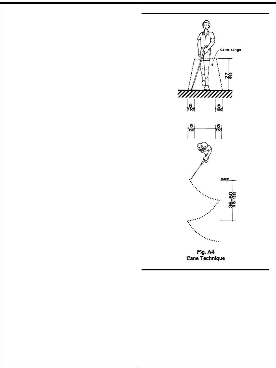
Pt. 36, App. ADepartment of Justice
567
semi-ambulatory person. There will be little
leeway for swaying or missteps (see Fig. A1).
A4.2.3 Wheelchair Turning Space.
These guidelines specify a minimum space of
60 in (1525 mm) diameter or a 60 in by 60 in
(1525 mm by 1525 mm) T-shaped space for a
pivoting 180-degree turn of a wheelchair. This
space is usually satisfactory for turning
around, but many people will not be able to
turn without repeated tries and bumping into
surrounding objects. The space shown in Fig.
A2 will allow most wheelchair users to com-
plete U-turns without difficulty.
A4.2.4 Clear Floor or Ground Space for
Wheelchairs. The wheelchair and user shown
in Fig. A3 represent typical dimensions for a
large adult male. The space requirements in
this guideline are based upon maneuvering
clearances that will accommodate most wheel-
chairs. Fig. A3 provides a uniform reference for
design not covered by this guideline.
A4.2.5 & A4.2.6 Reach. Reach ranges for
persons seated in wheelchairs may be further
clarified by Fig. A3(a). These drawings ap-
proximate in the plan view the information
shown in Fig. 4, 5, and 6.
A4.3 Accessible Route.
A4.3.1 General.
(1) Travel Distances. Many people with
mobility impairments can move at only very
slow speeds; for many, traveling 200 ft (61 m)
could take about 2 minutes. This assumes a
rate of about 1.5 ft/s (455 mm/s) on level
ground. It also assumes that the traveler would
move continuously. However, on trips over 100
ft (30 m), disabled people are apt to rest fre-
quently, which substantially increases their
trip times. Resting periods of 2 minutes for
every 100 ft (30 m) can be used to estimate
travel times for people with severely limited
stamina. In inclement weather, slow progress
and resting can greatly increase a disabled
person’s exposure to the elements.
(2) Sites. Level, indirect routes or those with
running slopes lower than 1:20 can sometimes
provide more convenience than direct routes
with maximum allowable slopes or with ramps.
A4.3.10 Egress. Because people with dis-
abilities may visit, be employed or be a resi-
dent in any building, emergency management
plans with specific provisions to ensure their
safe evacuation also play an essential role in
fire safety and life safety.
A4.3.11.3 Stairway Width. A 48 in (1220
mm) wide exit stairway is needed to allow
assisted evacuation (e.g., carrying a person in
a wheelchair) without encroaching on the exit
path for ambulatory persons.
A4.3 Accessible Route
A4

Pt. 36, App. A 28 CFR Ch. I (7-1-94 Edition)
568
A4.3.11.4 Two-way Communication. It is
essential that emergency communication not
be dependent on voice communications alone
because the safety of people with hearing or
speech impairments could be jeopardized. The
visible signal requirement could be satisfied
with something as simple as a button in the
area of rescue assistance that lights, indicat-
ing that help is on the way, when the mes-
sage is answered at the point of entry.
A4.4 Protruding Objects.
A4.4.1 General. Service animals are trained
to recognize and avoid hazards. However, most
people with severe impairments of vision use
the long cane as an aid to mobility. The two
principal cane techniques are the touch
technique, where the cane arcs from side to
side and touches points outside both shoul-
ders; and the diagonal technique, where the
cane is held in a stationary position diagonally
across the body with the cane tip touching or
just above the ground at a point outside one
shoulder and the handle or grip extending to a
point outside the other shoulder. The touch
technique is used primarily in uncontrolled
areas, while the diagonal technique is used
primarily in certain limited, controlled, and
familiar environments. Cane users are often
trained to use both techniques.
Potential hazardous objects are noticed only if
they fall within the detection range of canes
(see Fig. A4). Visually impaired people walking
toward an object can detect an overhang if its
lowest surface is not higher than 27 in (685
mm). When walking alongside protruding
objects, they cannot detect overhangs. Since
proper cane and service animal techniques
keep people away from the edge of a path or
from walls, a slight overhang of no more than 4
in (100 mm) is not hazardous.
A4.5 Ground and Floor Surfaces.
A4.5.1 General. People who have difficulty
walking or maintaining balance or who use
crutches, canes, or walkers, and those with
restricted gaits are particularly sensitive to
slipping and tripping hazards. For such people,
a stable and regular surface is necessary for
safe walking, particularly on stairs. Wheel-
chairs can be propelled most easily on sur-
faces that are hard, stable, and regular. Soft
loose surfaces such as shag carpet, loose sand
or gravel, wet clay, and irregular surfaces such
as cobblestones can significantly impede
wheelchair movement.
Slip resistance is based on the frictional force
necessary to keep a shoe heel or crutch tip from
slipping on a walking surface under conditions
likely to be found on the surface. While the
dynamic coefficient of friction during walking
varies in a complex and non-uniform way, the
static coefficient of friction, which can be
measured in several ways, provides a close
approximation of the slip resistance of a
surface. Contrary to popular belief, some
slippage is necessary to walking, especially for
persons with restricted gaits; a truly “non-slip”
surface could not be negotiated.
The Occupational Safety and Health Adminis-
tration recommends that walking surfaces
have a static coefficient of friction of 0.5. A
research project sponsored by the Architectural
and Transportation Barriers Compliance Board
(Access Board) conducted tests with persons
with disabilities and concluded that a higher
coefficient of friction was needed by such
persons. A static coefficient of friction of 0.6 is
recommended for accessible routes and 0.8 for
ramps.
It is recognized that the coefficient of friction
varies considerably due to the presence of
contaminants, water, floor finishes, and other
factors not under the control of the designer or
builder and not subject to design and construc-
tion guidelines and that compliance would be
difficult to measure on the building site. Never-
theless, many common building materials
suitable for flooring are now labeled with
information on the static coefficient of friction.
While it may not be possible to compare one
product directly with another, or to guarantee a
constant measure, builders and designers are
encouraged to specify materials with appropri-
ate values. As more products include informa-
tion on slip resistance, improved uniformity in
measurement and specification is likely. The
Access Board’s advisory guidelines on Slip
Resistant Surfaces provides additional infor-
mation on this subject.
Cross slopes on walks and ground or floor
surfaces can cause considerable difficulty in
propelling a wheelchair in a straight line.
A4.5 Ground and Floor Surfaces
A5

Pt. 36, App. ADepartment of Justice
569
A4.5.3 Carpet. Much more needs to be done
in developing both quantitative and qualitative
criteria for carpeting (i.e., problems associated
with texture and weave need to be studied).
However, certain functional characteristics are
well established. When both carpet and pad-
ding are used, it is desirable to have minimum
movement (preferably none) between the floor
and the pad and the pad and the carpet which
would allow the carpet to hump or warp. In
heavily trafficked areas, a thick, soft (plush)
pad or cushion, particularly in combination
with long carpet pile, makes it difficult for
individuals in wheelchairs and those with
other ambulatory disabilities to get about. Firm
carpeting can be achieved through proper
selection and combination of pad and carpet,
sometimes with the elimination of the pad or
cushion, and with proper installation.
Carpeting designed with a weave that causes
a zig-zag effect when wheeled across is
strongly discouraged.
A4.6 Parking and Passenger Loading
Zones.
A4.6.3 Parking Spaces. The increasing use
of vans with side-mounted lifts or ramps by
persons with disabilities has necessitated
some revisions in specifications for parking
spaces and adjacent access aisles. The
typical accessible parking space is 96 in
(2440 mm) wide with an adjacent 60 in (1525
mm) access aisle. However, this aisle does not
permit lifts or ramps to be deployed and still
leave room for a person using a wheelchair or
other mobility aid to exit the lift platform or
ramp. In tests conducted with actual lift/van/
wheelchair combinations, (under a
Board-sponsored Accessible Parking and
Loading Zones Project) researchers found that
a space and aisle totaling almost 204 in (5180
mm) wide was needed to deploy a lift and exit
conveniently. The “van accessible” parking
space required by these guidelines provides a
96 in (2440 mm) wide space with a 96 in (2440
mm) adjacent access aisle which is just wide
enough to maneuver and exit from a side
mounted lift. If a 96 in (2440 mm) access aisle
is placed between two spaces, two “van
accessible” spaces are created. Alternatively,
if the wide access aisle is provided at the end
of a row (an area often unused), it may be
possible to provide the wide access aisle
without additional space (see Fig. A5(a)).
A sign is needed to alert van users to the
presence of the wider aisle, but the space is
not intended to be restricted only to vans.
“Universal” Parking Space Design. An alter-
native to the provision of a percentage of
spaces with a wide aisle, and the associated
need to include additional signage, is the use
of what has been called the “universal”
parking space design. Under this design, all
accessible spaces are 132 in (3350 mm) wide
with a 60 in (1525 mm) access aisle (see Fig.
A5(b)). One advantage to this design is that
A4.6 Parking and Passenger Loading Zones
A6

Pt. 36, App. A 28 CFR Ch. I (7-1-94 Edition)
570
no additional signage is needed because all
spaces can accommodate a van with a
side-mounted lift or ramp. Also, there is no
competition between cars and vans for spaces
since all spaces can accommodate either.
Furthermore, the wider space permits vehicles
to park to one side or the other within the 132
in (3350 mm) space to allow persons to exit
and enter the vehicle on either the driver or
passenger side, although, in some cases, this
would require exiting or entering without a
marked access aisle.
An essential consideration for any design is
having the access aisle level with the parking
space. Since a person with a disability, using
a lift or ramp, must maneuver within the
access aisle, the aisle cannot include a ramp
or sloped area. The access aisle must be
connected to an accessible route to the
appropriate accessible entrance of a building
or facility. The parking access aisle must
either blend with the accessible route or have
a curb ramp complying with 4.7. Such a curb
ramp opening must be located within the
access aisle boundaries, not within the
parking space boundaries. Unfortunately,
many facilities are designed with a ramp that
is blocked when any vehicle parks in the
accessible space. Also, the required dimen-
sions of the access aisle cannot be restricted
by planters, curbs or wheel stops.
A4.6.4 Signage. Signs designating parking
places for disabled people can be seen from a
driver’s seat if the signs are mounted high
enough above the ground and located at the
front of a parking space.
A4.6.5 Vertical Clearance. High-top vans,
which disabled people or transportation
services often use, require higher clearances in
parking garages than automobiles.
A4.8 Ramps.
A4.8.1 General. Ramps are essential for
wheelchair users if elevators or lifts are not
available to connect different levels. However,
some people who use walking aids have
difficulty with ramps and prefer stairs.
A4.8.2 Slope and Rise. Ramp slopes be-
tween 1:16 and 1:20 are preferred. The ability
to manage an incline is related to both its
slope and its length. Wheelchair users with
disabilities affecting their arms or with low
stamina have serious difficulty using inclines.
Most ambulatory people and most people who
use wheelchairs can manage a slope of 1:16.
Many people cannot manage a slope of 1:12 for
30 ft (9 m).
A4.8.4 Landings. Level landings are essen-
tial toward maintaining an aggregate slope
that complies with these guidelines. A ramp
landing that is not level causes individuals
using wheelchairs to tip backward or bottom
out when the ramp is approached.
A4.8.5 Handrails. The requirements for stair
and ramp handrails in this guideline are for
adults. When children are principal users in a
building or facility, a second set of handrails at
an appropriate height can assist them and aid
in preventing accidents.
A4.9 Stairs.
A4.9.1 Minimum Number. Only interior and
exterior stairs connecting levels that are not
connected by an elevator, ramp, or other
accessible means of vertical access have to
comply with 4.9.
A4.10 Elevators.
A4.10.6 Door Protective and Reopening
Device. The required door reopening device
would hold the door open for 20 seconds if the
doorway remains obstructed. After 20 seconds,
the door may begin to close. However, if
designed in accordance with ASME
A17.1-1990, the door closing movement could
still be stopped if a person or object exerts
sufficient force at any point on the door edge.
A4.10.7 Door and Signal Timing for Hall
Calls. This paragraph allows variation in the
location of call buttons, advance time for
warning signals, and the door-holding period
used to meet the time requirement.
A4.10.12 Car Controls. Industry-wide
standardization of elevator control panel
design would make all elevators significantly
more convenient for use by people with severe
visual impairments. In many cases, it will be
possible to locate the highest control on
elevator panels within 48 in (1220 mm) from
the floor.
A4.8 Ramps
A7

Pt. 36, App. ADepartment of Justice
571
A4.10.13 Car Position Indicators. A special
button may be provided that would activate the
audible signal within the given elevator only
for the desired trip, rather than maintaining
the audible signal in constant operation.
A4.10.14 Emergency Communications. A
device that requires no handset is easier to
use by people who have difficulty reaching.
Also, small handles on handset compartment
doors are not usable by people who have
difficulty grasping.
Ideally, emergency two-way communication
systems should provide both voice and visual
display intercommunication so that persons
with hearing impairments and persons with
vision impairments can receive information
regarding the status of a rescue. A voice
intercommunication system cannot be the
only means of communication because it is
not accessible to people with speech and
hearing impairments. While a voice intercom-
munication system is not required, at a
minimum, the system should provide both an
audio and visual indication that a rescue is
on the way.
A4.11 Platform Lifts (Wheelchair
Lifts).
A4.11.2 Other Requirements. Inclined
stairway chairlifts, and inclined and vertical
platform lifts (wheelchair lifts) are available
for short-distance, vertical transportation of
people with disabilities. Care should be taken
in selecting lifts as some lifts are not equally
suitable for use by both wheelchair users and
semi-ambulatory individuals.
A4.12 Windows.
A4.12.1 General. Windows intended to be
operated by occupants in accessible spaces
should comply with 4.12.
A4.12.2 Window Hardware. Windows
requiring pushing, pulling, or lifting to open
(for example, double-hung, sliding, or case-
ment and awning units without cranks)
should require no more than 5 lbf (22.2 N) to
open or close. Locks, cranks, and other
window hardware should comply with 4.27.
A4.13 Doors.
A4.13.8 Thresholds at Doorways. Thresh-
olds and surface height changes in doorways
are particularly inconvenient for wheelchair
users who also have low stamina or restric-
tions in arm movement because complex
maneuvering is required to get over the level
change while operating the door.
A4.13.9 Door Hardware. Some disabled
persons must push against a door with their
chair or walker to open it. Applied kickplates
on doors with closers can reduce required
maintenance by withstanding abuse from
wheelchairs and canes. To be effective, they
should cover the door width, less approxi-
mately 2 in (51 mm), up to a height of 16 in
(405 mm) from its bottom edge and be cen-
tered across the width of the door.
A4.13.10 Door Closers. Closers with delayed
action features give a person more time to
maneuver through doorways. They are particu-
larly useful on frequently used interior doors
such as entrances to toilet rooms.
A4.13.11 Door Opening Force. Although
most people with disabilities can exert at least
5 lbf (22.2N), both pushing and pulling from a
stationary position, a few people with severe
disabilities cannot exert 3 lbf (13.13N). Al-
though some people cannot manage the
allowable forces in this guideline and many
others have difficulty, door closers must have
certain minimum closing forces to close doors
satisfactorily. Forces for pushing or pulling
doors open are measured with a push-pull
scale under the following conditions:
(1) Hinged doors: Force applied perpendicu-
lar to the door at the door opener or 30 in (760
mm) from the hinged side, whichever is farther
from the hinge.
(2) Sliding or folding doors: Force applied
parallel to the door at the door pull or latch.
(3) Application of force: Apply force gradually
so that the applied force does not exceed the
resistance of the door. In high-rise buildings,
air-pressure differentials may require a modifi-
cation of this specification in order to meet
the functional intent.
A4.11 Platform Lifts (Wheelchair Lifts)
A8
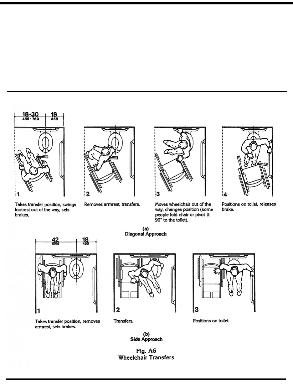
Pt. 36, App. A 28 CFR Ch. I (7-1-94 Edition)
572
A4.13.12 Automatic Doors and
Power-Assisted Doors. Sliding automatic
doors do not need guard rails and are more
convenient for wheelchair users and visually
impaired people to use. If slowly opening
automatic doors can be reactivated before their
closing cycle is completed, they will be more
convenient in busy doorways.
A4.15 Drinking Fountains and
Water Coolers.
A4.15.2 Spout Height. Two drinking foun-
tains, mounted side by side or on a single
post, are usable by people with disabilities
and people who find it difficult to bend over.
A4.15 Drinking Fountains and Water Coolers
A9

Pt. 36, App. ADepartment of Justice
573
A4.16 Water Closets.
A4.16.3 Height. Height preferences for toilet
seats vary considerably among disabled people.
Higher seat heights may be an advantage to
some ambulatory disabled people, but are often
a disadvantage for wheelchair users and
others. Toilet seats 18 in (455 mm) high seem
to be a reasonable compromise. Thick seats
and filler rings are available to adapt standard
fixtures to these requirements.
A4.16.4 Grab Bars. Fig. A6(a) and (b) show
the diagonal and side approaches most com-
monly used to transfer from a wheelchair to a
water closet. Some wheelchair users can
transfer from the front of the toilet while others
use a 90-degree approach. Most people who
use the two additional approaches can also use
either the diagonal approach or the side
approach.
A4.16.5 Flush Controls. Flush valves and
related plumbing can be located behind walls
or to the side of the toilet, or a toilet seat lid
can be provided if plumbing fittings are directly
behind the toilet seat. Such designs reduce the
chance of injury and imbalance caused by
leaning back against the fittings. Flush con-
trols for tank-type toilets have a standardized
mounting location on the left side of the tank
(facing the tank). Tanks can be obtained by
special order with controls mounted on the
right side. If administrative authorities require
flush controls for flush valves to be located in a
position that conflicts with the location of the
rear grab bar, then that bar may be split or
shifted toward the wide side of the toilet area.
A4.17 Toilet Stalls.
A4.17.3 Size and Arrangement. This
section requires use of the 60 in (1525 mm)
standard stall (Figure 30(a)) and permits the
36 in (915 mm) or 48 in (1220 mm) wide
alternate stall (Figure 30(b)) only in alter-
ations where provision of the standard stall is
technically infeasible or where local plumbing
codes prohibit reduction in the number of
fixtures. A standard stall provides a clear
space on one side of the water closet to enable
persons who use wheelchairs to perform a
side or diagonal transfer from the wheelchair
to the water closet. However, some persons
with disabilities who use mobility aids such
as walkers, canes or crutches are better able
to use the two parallel grab bars in the 36 in
(915 mm) wide alternate stall to achieve a
standing position.
In large toilet rooms, where six or more toilet
stalls are provided, it is therefore required
that a 36 in (915 mm) wide stall with parallel
grab bars be provided in addition to the
standard stall required in new construction.
The 36 in (915 mm) width is necessary to
achieve proper use of the grab bars; wider
stalls would position the grab bars too far
apart to be easily used and narrower stalls
would position the grab bars too close to the
water closet. Since the stall is primarily
intended for use by persons using canes,
crutches and walkers, rather than wheel-
chairs, the length of the stall could be conven-
tional. The door, however, must swing out-
ward to ensure a usable space for people who
use crutches or walkers.
A4.17.5 Doors. To make it easier for wheel-
chair users to close toilet stall doors, doors
can be provided with closers, spring hinges, or
a pull bar mounted on the inside surface of
the door near the hinge side.
A4.19 Lavatories and Mirrors.
A4.19.6 Mirrors. If mirrors are to be used by
both ambulatory people and wheelchair users,
then they must be at least 74 in (1880 mm)
high at their topmost edge. A single full length
mirror can accommodate all people, including
children.
A4.21 Shower Stalls.
A4.21.1 General. Shower stalls that are 36 in
by 36 in (915 mm by 915 mm) wide provide
additional safety to people who have difficulty
maintaining balance because all grab bars and
walls are within easy reach. Seated people use
the walls of 36 in by 36 in (915 mm by 915
mm) showers for back support. Shower stalls
that are 60 in (1525 mm) wide and have no
curb may increase usability of a bathroom by
wheelchair users because the shower area
provides additional maneuvering space.
A4.22 Toilet Rooms.
A4.22.3 Clear Floor Space. In many small
facilities, single-user restrooms may be the
only facilities provided for all building users.
A4.16 Water Closets
A10

Pt. 36, App. A 28 CFR Ch. I (7-1-94 Edition)
574
In addition, the guidelines allow the use of
“unisex” or “family” accessible toilet rooms in
alterations when technical infeasibility can be
demonstrated. Experience has shown that the
provision of accessible “unisex” or single-user
restrooms is a reasonable way to provide
access for wheelchair users and any atten-
dants, especially when attendants are of the
opposite sex. Since these facilities have
proven so useful, it is often considered advan-
tageous to install a “unisex” toilet room in
new facilities in addition to making the
multi-stall restrooms accessible, especially in
shopping malls, large auditoriums, and
convention centers.
Figure 28 (section 4.16) provides minimum
clear floor space dimensions for toilets in
accessible “unisex” toilet rooms. The dotted
lines designate the minimum clear floor
space, depending on the direction of approach,
required for wheelchair users to transfer onto
the water closet. The dimensions of 48 in
(1220 mm) and 60 in (1525 mm), respectively,
correspond to the space required for the two
common transfer approaches utilized by
wheelchair users (see Fig. A6). It is important
to keep in mind that the placement of the
lavatory to the immediate side of the water
closet will preclude the side approach transfer
illustrated in Figure A6(b).
To accommodate the side transfer, the space
adjacent to the water closet must remain
clear of obstruction for 42 in (1065 mm) from
the centerline of the toilet (Figure 28) and the
lavatory must not be located within this clear
space. A turning circle or T-turn, the clear floor
space at the lavatory, and maneuvering space
at the door must be considered when deter-
mining the possible wall locations. A privacy
latch or other accessible means of ensuring
privacy during use should be provided at the
door.
RECOMMENDATIONS:
1. In new construction, accessible single-user
restrooms may be desirable in some situa-
tions because they can accommodate a wide
variety of building users. However, they
cannot be used in lieu of making the
multi-stall toilet rooms accessible as required.
2. Where strict compliance to the guidelines
for accessible toilet facilities is technically
infeasible in the alteration of existing facili-
ties, accessible “unisex” toilets are a reason-
able alternative.
3. In designing accessible single-user
restrooms, the provisions of adequate space
to allow a side transfer will provide accommo-
dation to the largest number of wheelchair
users.
A4.22 Toilet Rooms
A11

Pt. 36, App. ADepartment of Justice
575
A4.23 Bathrooms, Bathing Facilities,
and Shower Rooms.
A4.23.3 Clear Floor Space. Figure A7
shows two possible configurations of a toilet
room with a roll-in shower. The specific shower
shown is designed to fit exactly within the
dimensions of a standard bathtub. Since the
shower does not have a lip, the floor space can
be used for required maneuvering space. This
would permit a toilet room to be smaller than
would be permitted with a bathtub and still
provide enough floor space to be considered
accessible. This design can provide accessibil-
ity in facilities where space is at a premium
(i.e., hotels and medical care facilities). The
alternate roll-in shower (Fig. 57b) also provides
sufficient room for the “T-turn” and does not
require plumbing to be on more than one wall.
A4.23.9 Medicine Cabinets. Other alterna-
tives for storing medical and personal care
items are very useful to disabled people.
Shelves, drawers, and floor-mounted cabinets
can be provided within the reach ranges of
disabled people.
A4.26 Handrails, Grab Bars, and Tub
and Shower Seats.
A4.26.1 General. Many disabled people rely
heavily upon grab bars and handrails to
maintain balance and prevent serious falls.
Many people brace their forearms between
supports and walls to give them more leverage
and stability in maintaining balance or for
lifting. The grab bar clearance of 1-1/2 in (38
mm) required in this guideline is a safety
clearance to prevent injuries resulting from
arms slipping through the openings. It also
provides adequate gripping room.
A4.26.2 Size and Spacing of Grab Bars
and Handrails. This specification allows for
alternate shapes of handrails as long as they
allow an opposing grip similar to that pro-
vided by a circular section of 1-1/4 in to 1-1/2
in (32 mm to 38 mm).
A4.27 Controls and Operating
Mechanisms.
A4.27.3 Height. Fig. A8 further illustrates
A4.23 Bathrooms, Bathing Facilities, and Shower Rooms
A12

Pt. 36, App. A 28 CFR Ch. I (7-1-94 Edition)
576
mandatory and advisory control mounting
height provisions for typical equipment.
Electrical receptacles installed to serve indi-
vidual appliances and not intended for regular
or frequent use by building occupants are not
required to be mounted within the specified
reach ranges. Examples would be receptacles
installed specifically for wall-mounted clocks,
refrigerators, and microwave ovens.
A4.28 Alarms.
A4.28.2 Audible Alarms. Audible emergency
signals must have an intensity and frequency
that can attract the attention of individuals who
have partial hearing loss. People over 60 years
of age generally have difficulty perceiving
frequencies higher than 10,000 Hz. An alarm
signal which has a periodic element to its
signal, such as single stroke bells (clang-
pause-clang- pause), hi-low (up-down-up-down)
and fast whoop (on-off-on-off) are best. Avoid
continuous or reverberating tones. Select a
signal which has a sound characterized by
three or four clear tones without a great deal
of “noise” in between.
A4.28.3 Visual Alarms. The specifications in
this section do not preclude the use of zoned or
coded alarm systems.
A4.28.4 Auxiliary Alarms. Locating visual
emergency alarms in rooms where persons who
are deaf may work or reside alone can ensure
that they will always be warned when an
emergency alarm is activated. To be effective,
such devices must be located and oriented so
that they will spread signals and reflections
throughout a space or raise the overall light
level sharply. However, visual alarms alone are
not necessarily the best means to alert sleep-
ers. A study conducted by Underwriters Labo-
ratory (UL) concluded that a flashing light
more than seven times brighter was required
(110 candela v. 15 candela, at the same
distance) to awaken sleepers as was needed to
alert awake subjects in a normal daytime
illuminated room.
For hotel and other rooms where people are
likely to be asleep, a signal-activated vibrator
placed between mattress and box spring or
under a pillow was found by UL to be much
more effective in alerting sleepers. Many
readily available devices are sound-activated
so that they could respond to an alarm clock,
clock radio, wake-up telephone call or room
smoke detector. Activation by a building alarm
system can either be accomplished by a
separate circuit activating an auditory alarm
which would, in turn, trigger the vibrator or by
a signal transmitted through the ordinary
110-volt outlet. Transmission of signals
through the power line is relatively simple and
is the basis of common, inexpensive remote
light control systems sold in many department
and electronic stores for home use. So-called
“wireless” intercoms operate on the same
principal.
A4.29 Detectable Warnings.
A4.29.2 Detectable Warnings on Walking
Surfaces. The material used to provide con-
trast should contrast by at least 70%. Contrast
in percent is determined by:
Contrast = [(B1 - B2)/B1] x 100
where B1 = light reflectance value (LRV) of the
lighter area and B2 = light reflectance value
(LRV) of the darker area.
Note that in any application both white and
black are never absolute; thus, B1 never
equals 100 and B2 is always greater than 0.
A4.30 Signage.
A4.30.1 General. In building complexes where
finding locations independently on a routine
basis may be a necessity (for example, college
campuses), tactile maps or prerecorded instruc-
tions can be very helpful to visually impaired
people. Several maps and auditory instructions
have been developed and tested for specific
applications. The type of map or instructions
used must be based on the information to be
communicated, which depends highly on the
type of buildings or users.
Landmarks that can easily be distinguished by
visually impaired individuals are useful as
orientation cues. Such cues include changes in
illumination level, bright colors, unique pat-
terns, wall murals, location of special equip-
ment or other architectural features.
Many people with disabilities have limitations
in movement of their heads and reduced
peripheral vision. Thus, signage positioned
A4.28 Alarms
A13

Pt. 36, App. ADepartment of Justice
577
perpendicular to the path of travel is easiest for
them to notice. People can generally distin-
guish signage within an angle of 30 degrees to
either side of the centerlines of their faces
without moving their heads.
A4.30.2 Character Proportion. The legibility
of printed characters is a function of the
viewing distance, character height, the ratio of
the stroke width to the height of the character,
the contrast of color between character and
background, and print font. The size of charac-
ters must be based upon the intended viewing
distance. A severely nearsighted person may
have to be much closer to recognize a character
of a given size than a person with normal visual
acuity.
A4.30.4 Raised and Brailled Characters
and Pictorial Symbol Signs (Pictograms).
The standard dimensions for literary Braille
are as follows:
Dot diameter .059 in.
Inter-dot spacing .090 in.
Horizontal separation
between cells .241 in.
Vertical separation
between cells .395 in.
Raised borders around signs containing raised
characters may make them confusing to read
unless the border is set far away from the
characters. Accessible signage with descriptive
materials about public buildings, monuments,
and objects of cultural interest may not
provide sufficiently detailed and meaningful
information. Interpretive guides, audio tape
devices, or other methods may be more effec-
tive in presenting such information.
A4.30.5 Finish and Contrast. An eggshell
finish (11 to 19 degree gloss on 60 degree
glossimeter) is recommended. Research indi-
cates that signs are more legible for persons
with low vision when characters contrast with
their background by at least 70 percent.
Contrast in percent shall be determined by:
Contrast = [(B1 - B2)/B1] x 100
where B1 = light reflectance value (LRV) of
the lighter area and B2 = light reflectance
value (LRV) of the darker area.
Note that in any application both white and
black are never absolute; thus, B1 never
equals 100 and B2 is always greater than 0.
The greatest readability is usually achieved
through the use of light-colored characters or
symbols on a dark background.
A4.30.7 Symbols of Accessibility for
Different Types of Listening Systems.
Paragraph 4 of this section requires signage
indicating the availability of an assistive
listening system. An appropriate message
should be displayed with the international
symbol of access for hearing loss since this
symbol conveys general accessibility for
people with hearing loss. Some suggestions
are:
INFRARED
ASSISTIVE LISTENING SYSTEM
AVAILABLE
----PLEASE ASK----
AUDIO LOOP IN USE
TURN T-SWITCH FOR
BETTER HEARING
----OR ASK FOR HELP----
FM
ASSISTIVE LISTENING
SYSTEM AVAILABLE
----PLEASE ASK----
The symbol may be used to notify persons of
the availability of other auxiliary aids and
services such as: real time captioning, cap-
tioned note taking, sign language interpret-
ers, and oral interpreters.
A4.30.8 Illumination Levels. Illumination
levels on the sign surface shall be in the 100
to 300 lux range (10 to 30 footcandles) and
shall be uniform over the sign surface. Signs
shall be located such that the illumination
level on the surface of the sign is not signifi-
cantly exceeded by the ambient light or
visible bright lighting source behind or in
front of the sign.
A4.30 Signage
A14

Pt. 36, App. A 28 CFR Ch. I (7-1-94 Edition)
578
A4.31 Telephones.
A4.31.3 Mounting Height. In localities where
the dial-tone first system is in operation, calls
can be placed at a coin telephone through the
operator without inserting coins. The operator
button is located at a height of 46 in (1170 mm)
if the coin slot of the telephone is at 54 in (1370
mm). A generally available public telephone
with a coin slot mounted lower on the equip-
ment would allow universal installation of
telephones at a height of 48 in (1220 mm) or
less to all operable parts.
A4.31.9 Text Telephones. A public text
telephone may be an integrated text telephone
pay phone unit or a conventional portable text
telephone that is permanently affixed within, or
adjacent to, the telephone enclosure. In order
to be usable with a pay phone, a text telephone
which is not a single integrated text telephone
pay phone unit will require a shelf large
enough (10 in (255mm) wide by 10 in (255 mm)
deep with a 6 in (150 mm) vertical clearance
minimum) to accommodate the device, an
electrical outlet, and a power cord. Movable or
portable text telephones may be used to
provide equivalent facilitation. A text telephone
should be readily available so that a person
using it may access the text telephone easily
and conveniently. As currently designed
pocket-type text telephones for personal use do
not accommodate a wide range of users. Such
devices would not be considered substantially
equivalent to conventional text telephones.
However, in the future as technology develops
this could change.
A4.32 Fixed or Built-in Seating
and Tables.
A4.32.4 Height of Tables or Counters.
Different types of work require different table or
counter heights for comfort and optimal perfor-
mance. Light detailed work such as writing
requires a table or counter close to elbow
height for a standing person. Heavy manual
work such as rolling dough requires a counter
or table height about 10 in (255 mm) below
elbow height for a standing person. This prin-
ciple of high/low table or counter heights also
applies for seated persons; however, the limiting
condition for seated manual work is clearance
under the table or counter.
Table A1 shows convenient counter heights for
seated persons. The great variety of heights for
comfort and optimal performance indicates a
need for alternatives or a compromise in height
if people who stand and people who sit will be
using the same counter area.
Table A1
Convenient Heights of Tables
and Counters for Seated People
1
Short Tall
Women Men
Conditions of Use in mm in mm
Seated in a wheelchair:
Manual work-
Desk or removable
armrests 26 660 30 760
Fixed, full-size armrests
2
32
3
815 32
3
815
Light, detailed work:
Desk or removable
armrests 29 735 34 865
Fixed, full-size armrests
2
32
3
815 34 865
Seated in a 16 in (405 mm)
high chair:
Manual work 26 660 27 685
Light, detailed work 28 710 31 785
1
All dimensions are based on a work-surface
thickness of 1 1/2 in (38 mm) and a clearance
of 1 1/2 in (38 mm) between legs and the
underside of a work surface.
2
This type of wheelchair arm does not interfere
with the positioning of a wheelchair under a
work surface.
3
This dimension is limited by the height of the
armrests: a lower height would be preferable.
Some people in this group prefer lower work
surfaces, which require positioning the wheel-
chair back from the edge of the counter.
A4.33 Assembly Areas.
A4.33.2 Size of Wheelchair Locations.
Spaces large enough for two wheelchairs allow
people who are coming to a performance
together to sit together.
A4.33.3 Placement of Wheelchair
Locations. The location of wheelchair areas
can be planned so that a variety of positions
A4.31 Telephones
A15

Pt. 36, App. ADepartment of Justice
579
within the seating area are provided. This will
allow choice in viewing and price categories.
Building/life safety codes set minimum
distances between rows of fixed seats with
consideration of the number of seats in a row,
the exit aisle width and arrangement, and the
location of exit doors. “Continental” seating,
with a greater number of seats per row and a
commensurate increase in row spacing and
exit doors, facilitates emergency egress for all
people and increases ease of access to
mid-row seats especially for people who walk
with difficulty. Consideration of this positive
attribute of “continental” seating should be
included along with all other factors in the
design of fixed seating areas.
Induction Loop
Transmitter: Transducer
wired to induction loop
around listening area.
Receiver: Self-contained
induction receiver or
personal hearing aid
with telecoil.
Cost-Effective
Low Maintenance
Easy to use
Unobtrusive
May be possible to
integrate into existing
public address system.
Some hearing aids can
function as receivers.
Signal spills over to
adjacent rooms.
Susceptible to electrical
interference.
Limited portability
Inconsistent signal
strength
Head position affects
signal strength.
Lack of standards for
induction coil
performance.
Meeting areas
Theaters
Churches and Temples
Conference rooms
Classrooms
TV viewing
FM
Transmitter: Flashlight-
sized worn by speaker.
Receiver: With personal
hearing aid via DAI or
induction neck-loop and
telecoil; or self-contain-
ed with earphone(s).
Highly portable
Different channels allow
use by different groups
within the same room.
High user mobility
Variable for large range
of hearing losses.
High cost of receivers
Equipment fragile
Equipment obtrusive
High maintenance
Expensive to maintain
Custom fitting to
individual user may be
required.
Classrooms
Tour groups
Meeting areas
Outdoor events
One-on-one
Infrared
Transmitter: Emitter in
line-of- sight with
receiver.
Receiver: Self-contained.
Or with personal hearing
aid via DAI or induction
neckloop and telecoil.
System Typical
Applications
Advantages Disadvantages
Easy to use
Insures privacy or
confidentiality
Moderate cost
Can often be integrated
into existing public
address system.
Line-of-sight required
between emitter and
receiver.
Ineffective outdoors
Limited portability
Requires installation
Source: Rehab Brief, National Institute on Disability and Rehabilitation Research, Washington, DC, Vol. XII, No. 10, (1990).
Table A2. Summary of Assistive Listening Devices
Theaters
Churches and Temples
Auditoriums
Meetings requiring
confidentiality
TV viewing
Table A2. Summary of Assistive Listening Devices
A16

Pt. 36, App. A 28 CFR Ch. I (7-1-94 Edition)
580
A4.33.6 Placement of Listening
Systems.
A distance of 50 ft (15 m) allows a
person to distinguish performers’ facial
expressions.
A4.33.7 Types of Listening Systems.
An
assistive listening system appropriate for an
assembly area for a group of persons or where
the specific individuals are not known in
advance, such as a playhouse, lecture hall or
movie theater, may be different from the system
appropriate for a particular individual provided
as an auxiliary aid or as part of a reasonable
accommodation. The appropriate device for an
individual is the type that individual can use,
whereas the appropriate system for an assembly
area will necessarily be geared toward the
“average” or aggregate needs of various
indi-viduals. A listening system that can be used
from any seat in a seating area is the most flexible
way to meet this specification. Earphone jacks
with variable volume controls can benefit only
people who have slight hearing loss and do not
help people who use hearing aids. At the present
time, magnetic induction loops are the most
feasible type of listening system for people who
use hearing aids equipped with “T-coils,” but
people without hearing aids or those with hearing
aids not equipped with inductive pick-ups cannot
use them without special receivers. Radio fre-
quency systems can be extremely effective and
inexpensive. People without hearing aids can use
them, but people with hearing aids need a special
receiver to use them as they are presently de-
signed. If hearing aids had a jack to allow a
by-pass of microphones, then radio frequency
systems would be suitable for people with and
without hearing aids. Some listening systems may
be subject to interference from other equipment
and feedback from hearing aids of people who are
using the systems. Such interference can be
controll-ed by careful engineering design that
anticipates feedback sources in the surrounding
area.
Table A2, reprinted from a National Institute of
Disability and Rehabilitation Research “Rehab
Brief,” shows some of the advantages and disad-
vantages of different types of assistive listening
systems. In addition, the Architectural and
Transportation Barriers Compliance Board
(Access Board) has published a pamphlet on
Assistive Listening Systems which lists demon-
stration centers across the country where
technical assistance can be obtained in selecting
and installing appropriate systems. The state of
New York has also adopted a detailed technical
specification which may be useful.
A5.0 Restaurants and Cafeterias.
A5.1 General.
Dining counters (where there is
no service) are typically found in small carry-out
restaurants, bakeries, or coffee shops and may
only be a narrow eating surface attached to a
wall. This section requires that where such a
dining counter is provided, a portion of the
counter shall be at the required accessible height.
A7.0 Business and Mercantile.
A7.2(3) Assistive Listening Devices.
At all
sales and service counters, teller windows, box
offices, and information kiosks where a physical
barrier separates service personnel and custom-
ers, it is recommended that at least one perma-
nently installed assistive listening device comply-
ing with 4.33 be provided at each location or
series. Where assistive listening devices are
installed, signage should be provided identifying
those stations which are so equipped.
A7.3 Check-out Aisles.
Section 7.2 refers to
counters without aisles; section 7.3 concerns
check-out aisles. A counter without an aisle (7.2)
can be approached from more than one direction
such as in a convenience store. In order to use a
check-out aisle (7.3), customers must enter a
defined area (an aisle) at a particular point, pay
for goods, and exit at a particular point.
A10.3 Fixed Facilities and Stations
A10.3.1(7) Route Signs.
One means of
making control buttons on fare vending ma-
chines usable by persons with vision impair-
ments is to raise them above the surrounding
surface. Those activated by a mechanical motion
are likely to be more detectable. If farecard
vending, collection, and adjustment devices are
designed to accommodate farecards having one
tactually distinctive corner, then a person who
has a vision impairment will insert the card with
greater ease. Token collection devices that are
designed to accommodate tokens which are
perforated can allow a person to distinguish more
readily between tokens and common coins.
Thoughtful placement of accessible gates and
fare vending machines in relation to inaccessible
devices will make their use and detection easier
for all persons with disabilities.
A5.0 Restaurants and Cafeterias
[56 FR 35592, July 26, 1991, as amended by Order No. 1679-93, 58 FR 17522, Apr. 5, 1993; Order
No. 1836-94, 59 FR 2675, Jan. 18, 1994]
A17
