A
MP+ 1.35 – 1.50 – 1.60 – 1.70
it
CALDAIA MURALE A GAS A CONDENSAZIONE
Manuale per l’uso destinato all’utente e all’installatore
en CONDENSING GAS WALL-HUNG BOILERS
Instructions manual for users and installers
de (AT) KONDENSATIONS-WANDGASHEIZKESSEL
Gebrauchsanleitung für den Benutzer und Installateur
es CALDERA MURAL DE GAS A CONDENSACIÓN
Manual de uso destinado al usuario y al instalador

7221369.01 (1-03/15) 24
User & Installer (en)
7221369.01 (1-03/15Dear Customer,
Our company is condent our new product will meet all your requirements. Buying one of our products guarantees all your
expectations: good performance combined with simple and rational use.
Please do not put this booklet away without reading it rst: it contains useful information for the correct and efcient use of your
product.
Our company declares that these products are marked in compliance with the essential requirements of the
following Directives:
- Gas Directive 2009/142/EC
- Electromagnetic Compatibility Directive 2004/108/EC
- Low Voltage Directive 2006/95/EC
- Directive ecodesign 2009/125/EC
- Regulation (EU) No 813/2013 - 811/2013
Our company, constantly striving to improve the products, reserves the right to modify the details given in this documentation
at any time and without notice. These Instructions are only meant to provide consumers with use information and under no
circumstance should they be construed as a contract with a third party.
The appliance can be used by children aged 8 or over and by people with reduced
physical, sensory or mental faculties, or who do not have the required experience
or knowledge, provided they are supervised or have received instructions on using
the appliance safely and understanding its intrinsic hazards. Children must not play
with the appliance. The cleaning and maintenance operations reserved to the user
must not be performed by unsupervised children.
CONTENT
DESCRIPTION OF SYMBOLS .....................................................................................................................................................................25
SAFETY WARNINGS .................................................................................................................................................................................... 25
GENERAL PRECAUTIONS .........................................................................................................................................................................26
ENERGY-SAVING TIPS ................................................................................................................................................................................ 26
1. COMMISSIONING THE BOILER ..................................................................................................................................................................27
1.1 ADJUSTING THE CH AND DHW FLOW TEMPERATURE ..........................................................................................................................27
1.2 OPERATING MODES ...................................................................................................................................................................................27
2. PROLONGED SHUTDOWN. ANTI-FREEZE PROTECTION .......................................................................................................................28
3. GAS CONVERSION .....................................................................................................................................................................................28
4. FAULTS .........................................................................................................................................................................................................28
5. BOILER INFORMATION MENU ...................................................................................................................................................................29
6. FILLING THE SYSTEM ................................................................................................................................................................................. 29
7. ROUTINE MAINTENANCE INSTRUCTIONS ...............................................................................................................................................29
8. SWITCHING OFF THE BOILER ...................................................................................................................................................................29
INSTRUCTIONS PRIOR TO INSTALLATION ...............................................................................................................................................30
9. INSTALLING THE BOILER ...........................................................................................................................................................................30
9.1 BOILER PUMP ..............................................................................................................................................................................................30
10. INSTALLING THE FLUE ...............................................................................................................................................................................31
10.1 CONCENTRIC DUCTS .................................................................................................................................................................................31
10.2 SEPARATE DUCTS ......................................................................................................................................................................................31
10.3 CASCADE DUCTS .......................................................................................................................................................................................32
11. ELECTRICAL CONNECTIONS .....................................................................................................................................................................32
11.1 CONNECTING THE ROOM THERMOSTAT .................................................................................................................................................33
11.2 ACCESSORIES NOT INCLUDED IN THE SUPPLY .....................................................................................................................................33
SETTING PARAMETERS USING THE REMOTE CONTROL ......................................................................................................................34
12. INITIAL IGNITION - SPECIAL FUNCTIONS .................................................................................................................................................36
12.1 SYSTEM GAS EXTRACTION FUNCTION ...................................................................................................................................................36
12.2 CALIBRATION FUNCTION ...........................................................................................................................................................................36
12.3 CHIMNEY SWEEPER ...................................................................................................................................................................................36
13. FAULTS THAT CANNOT BE RESET BY THE USER ...................................................................................................................................36
14. PARAMETERS SETTING .............................................................................................................................................................................37
15. GAS VALVE CALIBRATION .......................................................................................................................................................................... 39
15.1 GAS CONVERSION .....................................................................................................................................................................................39
16. ADJUSTMENT AND SAFETY DEVICES ......................................................................................................................................................40
17. PUMP CAPACITY/ HEAD .............................................................................................................................................................................40
18. ANNUAL SERVICING ...................................................................................................................................................................................41
18.1 CLEANING THE CONDESATE TRAP ..........................................................................................................................................................41
18.2 CLEANING THE HEAT EXCHANGER FUMES SIDE ................................................................................................................................... 41
18.3 CHECKING THE BURNER ...........................................................................................................................................................................42
18.4 COMBUSTION PARAMETERS ....................................................................................................................................................................42
19. DISMANTLING, DISPOSAL AND RECYCLING ...........................................................................................................................................42
20. TECHNICAL SPECIFICATIONS ...................................................................................................................................................................43
21. TECHNICAL PARAMETERS ........................................................................................................................................................................44
22. PRODUCT FICHE .........................................................................................................................................................................................45

25
User & Installer (en)
7221369.01 (1-03/15)
DESCRIPTION OF SYMBOLS
WARNING
Risk of damage to or malfunction of the appliance. Pay special attention to the warnings concerning
danger to people.
DANGER OF BURNS
Wait for the appliance to cool down before working on the parts exposed to heat.
DANGER - HIGH VOLTAGE
Live components - electrocution hazard.
DANGER OF FREEZING
Possible formation of ice due to low temperatures.
IMPORTANT INFORMATION
Information to read with particular care as it is useful for the correct operation of the boiler.
GENERIC PROHIBITION
It is forbidden to do/use the things indicated alongside the symbol.
SAFETY WARNINGS
SMELL OF GAS
• Switch off the boiler.
• Do not activate any electrical device (such as switching on the light).
• Put out any naked ames and open the windows.
• Call an Authorised Service Centre.
SMELL OF COMBUSTION FUMES
• Switch off the boiler.
• Open all the doors and windows to ventilate the room.
• Call an Authorised Service Centre.
FLAMMABLE MATERIAL
Do not use and/or store highly ammable material (thinners, paper, etc.) near the boiler.
SERVICING AND CLEANING THE BOILER
Switch off the boiler before working on it.
The appliance is not intended to be used by persons with reduced physical, sensory or mental capacities, or who lack
experience or knowledge, unless, through the mediation of a person responsible for their safety, they have had the benet
of supervision or of instructions on the use of the appliance.
BAXI a leading European manufacturer of hi-tech boilers and heating systems, has developed
CSQ-certied quality management (ISO 9001), environmental (ISO 14001) and health and
safety (OHSAS 18001) systems. This means that BAXI S.p.A. includes among its objectives the
safeguarding of the environment, the reliability and quality of its products, and the health and
safety of its employees.
Through its organisation, the company is constantly committed to implementing and improving
these aspects in favour of customer satisfaction.

7221369.01 (1-03/15) 26
User & Installer (en)
GENERAL PRECAUTIONS
This boiler has been designed to heat water to a temperature lower than boiling point at atmospheric pressure. It must be
connected to a central heating system and to a domestic hot water supply system according to its performance and power output.
Before having the boiler installed by a qualied service engineer, make sure the following operations are performed:
• Make sure that the boiler is adjusted to use the type of gas delivered by the gas supply. To do this, check the markings on the
packaging and the data label on the appliance.
• Make sure that the ue terminal draft is appropriate, that the terminal is not obstructed and that no exhaust gases from other
appliances are expelled through the same ue duct, unless the latter has been specially designed to collect exhaust gas from
more than one appliance, in compliance with current laws and regulations.
• Make sure that, if the boiler is connected to existing ue ducts, these have been thoroughly cleaned as residual products of
combustion may detach from the walls during operation and obstruct the ow of fumes.
• To ensure correct operation and maintain the warranty, observe the following precautions:
1. DHW circuit
1.1 If the water is harder than 20 °F (1 °F = 10 mg calcium carbonate per litre of water), install a polyphosphate dispenser or an
equivalent treatment system, compliant with current regulations.
1.2 Thoroughly ush the system after installation of the appliance and before use.
1.3 The materials used for the DHW circuit comply with Directive 98/83/EC.
2. Heating circuit
2.1 New system: Before installing the boiler, the system must be cleaned and ushed to eliminate residual thread-cutting swarf,
solder and any solvents, using suitable off-the-shelf non-acid and non-alkaline products that do not damage metal, plastic and
rubber parts. To protect the system from scale, use inhibitors such as SENTINEL X100 and FERNOX protector for heating circuits.
Use these products in strict compliance with the manufacturers' instructions.
2.2 Existing system: Before installing the boiler, drain the system and clean it to remove sludge and contaminants, using suitable
proprietary products. Recommended cleaning products are: SENTINEL X300 or X400 and FERNOX regenerator for heating
circuits. Use these products in strict compliance with the manufacturers' instructions. Remember that the presence of foreign
bodies in the heating system can adversely affect boiler operation (e.g. overheating and excessive noise of the heat exchanger).
Initial lighting of the boiler must be carried out by an authorised Service Engineer who must rst ensure that:
• The rated data correspond to the supply (electricity, water and gas) data.
• That the installation complies with current regulations.
• The appliance is correctly connected to the power supply and earthed.
The appliance must be installed in a ventilated boiler room pursuant to current regulations (appliances with heating capacity
> 40 kW). The regulations for appliances with heating capacity > 40 kW to not apply to model Luna Duo-tec MP 1.35.
Failure to observe the above will render the warranty null and void. The names of the Authorised Service Centres are
indicated in the attached sheet. Prior to commissioning, remove the protective plastic coating from the boiler. Do not use
any tools or abrasive detergents to do this as you may damage the painted surfaces.
Do not leave any packaging (plastic bags, polystyrene, etc.) within the reach of children as they are a potential source of danger.
ENERGY-SAVING TIPS
Adjustment in the heating mode
Adjust the boiler ow temperature depending on the kind of system. For systems with radiators, set a maximum heating water ow
temperature of approximately 60°C, and increase this value if the required room temperature is not reached. For systems with
radiant oor panels, do not exceed the temperature indicated by the system designer. Use the External Sensor and/or Control
Panel to automatically adjust the ow temperature to atmospheric conditions or the indoor temperature. This ensures that no more
heat than that effectively necessary is produced. Adjust the room temperature without overheating the rooms. Every extra degree
centigrade means consuming approximately 6% more. Also room ambient temperature depending on how the rooms are used.
For example, the bedroom or the least used rooms can be heated to a lower temperature. Use the programmable timer and set the
night-time room temperature at approximately 5°C lower than that during the day. There is no appreciable saving to be achieved
by setting it any lower. Only in case of a prolonged absence, such as a holiday, should the temperature setpoint be lowered. Do
not cover radiators as this prevents the air from circulating correctly. Do not leave the windows partially open to ventilate the rooms
but open them completely for a short period.
Domestic hot water
Setting the domestic hot water at the required temperature without mixing it with cold water saves a lot of money. Additional
heating wastes energy and creates additional scale.

27
USER Section (en)
7221369.01 (1-03/15)
1. COMMISSIONING THE BOILER
To light the boiler correctly, proceed as follows:
• Check that the system pressure is correct (section 6);
• Power the boiler;
• Open the gas tap (yellow, positioned under the boiler);
• Select the required heating mode (section 1.2).
During initial ignition, the burner may not ignite (causing the boiler to shut down) until any air in the gas pipes is vented.
In this case, repeat the ignition procedure until gas reaches the burner. To reset boiler operation, press for at least 2
seconds.
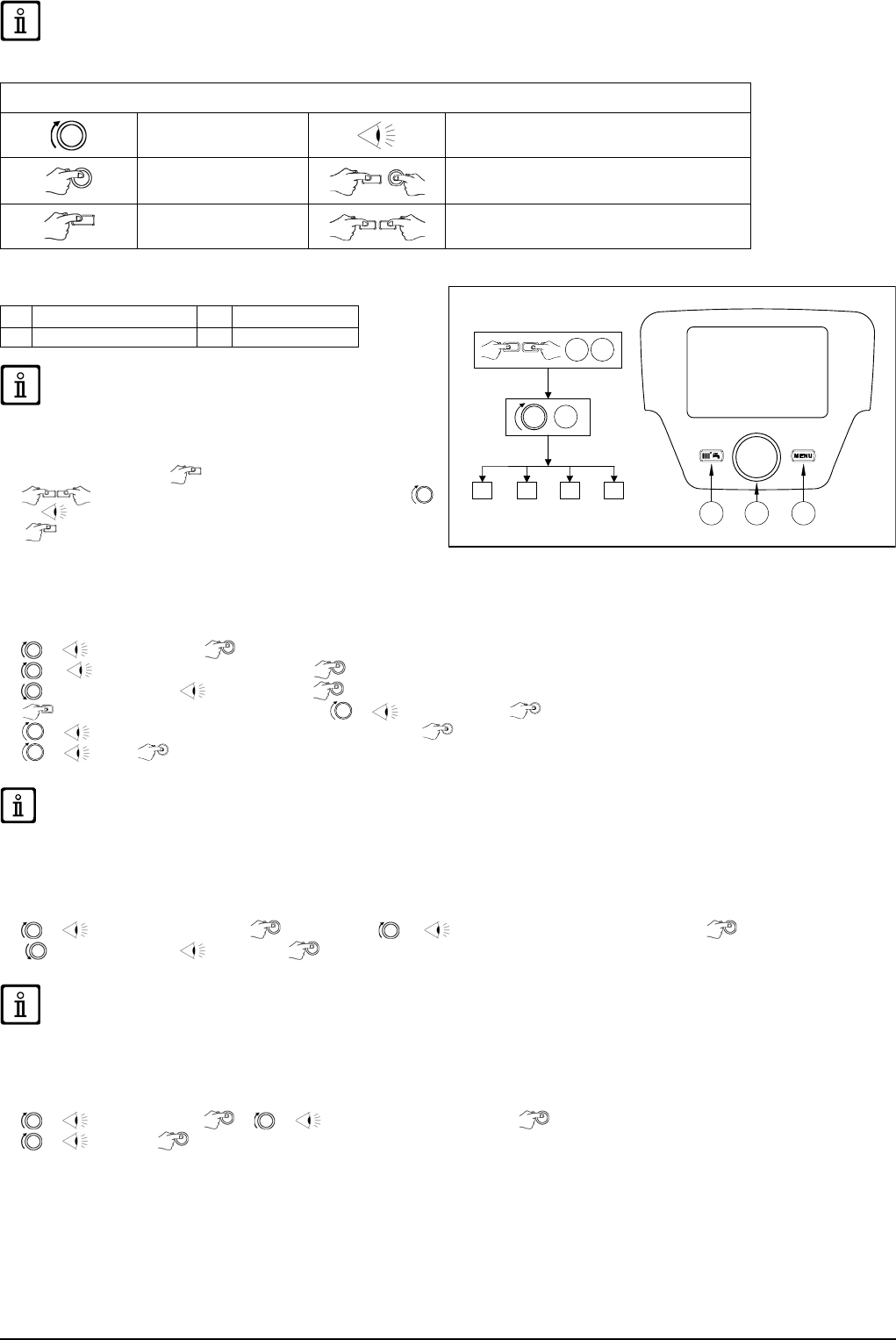
Key to BUTTONS
DHW temperature adjustment
(+ to increase the temperature and – to decrease it)
Heating water temperature adjustment
(+ to increase the temperature and – to decrease it)
Boiler operating information
Operating mode:
DHW – DHW & Heating – Heating Only
Off – Reset – Exit menu/functions
Key to SYMBOLS
Off: heating and DHW disabled
(only boiler anti-freeze protection is active)
Burner lit
Fault preventing the burner from lighting DHW operating mode enabled
Boiler/system water pressure low Heating mode enabled
Technical Service Centre call-in Programming menu
Manually resettable fault ( )
Boiler information menu
Fault in progress Set unit of measurement (SI/US)
1.1 ADJUSTING THE CH AND DHW FLOW TEMPERATURE
Press and respectively to adjust the CH and DHW ow temperature (if an external storage boiler is tted). When
the burner is lit, the display shows the symbol .
HEATING: while the boiler is operating in the heating mode, the display shows the ashing symbol and the heating delivery
temperature (°C).
When connected to an External Sensor, indirectly adjust the room temperature (factory setting 20°C).
DHW: connect an external storage boiler to produce domestic hot water. While the boiler is operating in the DHW mode, the
display shows the ashing symbol and the heating ow temperature (°C).
1.2 OPERATING MODES
SYMBOL
DISPLAYED
OPERATING MODE
To enable the appliance in DHW - Heating or Heating only press
repeatedly
and choose one of the three available modes.
To disable the boiler operating modes whilst keeping the anti-freeze function
enabled, press
. Just the symbol appears on the display (with the boiler
not blocked).
DHW
DHW & HEATING
HEATING ONLY

7221369.01 (1-03/15) 28
USER Section (en)
2. PROLONGED SHUTDOWN. ANTI-FREEZE PROTECTION
Do not drain the whole system as lling up with water again could cause unnecessary and harmful scale to build up inside the
boiler and the heating elements. If the boiler is not used during winter and is therefore exposed to the danger of frost, add some
specic anti-freeze to the water in the system (e.g.: propylene glycol coupled with corrosion and scale inhibitors). The electronic
boiler management system includes a “frost protection” function for the heating system which, when delivery temperature falls
below 5°C, lights the burner until a delivery temperature of 30°C is reached.
The function is operative if: the boiler is electrically powered, there is gas, system pressure is normal and the boiler is not
blocked.
3. GAS CONVERSION
The boilers can operate both on natural gas (G20) and LPG (G31). All gas conversions must be made by the AUTHORISED
TECHNICAL SERVICE CENTRE.
4. FAULTS
The faults shown on the display are identied with the symbol and a number (fault code). For a
complete list of faults, see the following table.
If appears on the display the fault must be RESET by the user.
To RESET the boiler, press . If faults are displayed frequently, call the Authorised Service Engineer.
FAULTS TABLE
Description of fault Description of fault
10
External probe sensor
125
No circulation safety trip
(control performed via a temperature sensor)
20
NTC ow sensor
128
No ame
28
NTC fumes sensor
130
Fumes NTC tripped due to overtemperature
40
NTC ow sensor
133
Ignition failure (4 attempts)
50
NTC DHW sensor
(only for heating-only model with storage boiler)
151
Boiler board internal fault
52
Solar DHW sensor (if connected to a solar plant)
152
Generic parameter setting error
73
Solar manifold sensor (if connected to a solar plant) 153 Hardware reset button pressed more than 10 seconds
83
Communication problem between boiler board and control unit.
Probable short circuit on wiring.
160
Fan fault
84
Address conict between control units
(internal fault)
321
NTC domestic hot water sensor faulty
98 Accessory not detected or recognized (*)
343
Generic parameter setting error of solar plant
(if connected to a solar plant)
109
Air in boiler circuit (temporary fault)
384
Abnormal light (parasite ame – internal fault)
110
Safety thermostat/exchanger ange thermostat (**) tripped due
to over temperature (pump probably blocked or air in heating
circuit)
385
Input voltage too low
111
Safety thermostat tripped due to overtemperature.
386
Fan speed threshold not reached
117
Pressure in hydraulic circuit too high
430
No circulation safety trip
(control performed via a pressure sensor)
118
Pressure in hydraulic circuit too low 432
No functional hearth or safety thermostat tripped due to over
temperature (E110)
(*) After powering up the boiler (or after a Reset for lockout), the error appears on the display once the self-check is completed. The fault code
is displayed permanently if the accessory is not recognized.
(**) See Section “ADJUSTMENT AND SAFETY DEVICES”.
In the event of a fault, the display backlighting indicates the error code. 5 reset attempts can be performed after which the
boiler shuts down. Wait 15 minutes before attempting to reset the boiler again.

29
USER Section (en)
7221369.01 (1-03/15)
5. BOILER INFORMATION MENU
Press to display the information indicated in the following table. Press to exit.
Description Description
00
SW Diagnostic Code
12
Ion current
01
Heating ow temperature
13
Burner working hours
02
Outdoor temperature (if the outdoor sensor is tted)
14
Zone 1 heating mode
03
External storage tank temperature (tted models)
15
Zone 2 heating mode
04
DHW temperature (tted models)
16
DHW circuit operating mode
05
Water pressure in heating system
17
Boiler operating mode
06
Heating return temperature
18
Solar plant operating mode
07
Flue sensor temperature
19
Manufacturer information
08
Not used
20
Manufacturer information
09
Solar collector temperature
21
Gas energy consumption in HEATING
10
Zone 1 heating ow temperature
22
Gas energy consumption in DHW
11
Zone 2 heating ow temperature
23
Gas energy consumption in HEATING + DHW
Items 21, 22 and 23 are displayed alternatively with the gas energy consumption value expressed in millions, thousands and units
of kWh. e.g.: 21 / 033 / 145 / 827 corresponds to a gas energy consumption in HEATING of 33.145.827 kWh.
6. FILLING THE SYSTEM
Periodically check that the pressure displayed on the pressure gauge is 1 - 1.5 bar, with the system cold. If it is lower, turn the
system lling tap installed by the installer. Open the tap very slowly in order to vent the air.
The boiler is tted with a hydraulic pressure gauge which prevents the boiler from working if there is no water.
If pressure drops occur frequently, have the boiler checked by the AUTHORISED TECHNICAL SERVICE CENTRE.
7. ROUTINE MAINTENANCE INSTRUCTIONS
To keep the boiler efcient and safe, have it checked by the Authorised Service Centre at the end of every operating period.
Careful servicing ensures economical operation of the system.
8. SWITCHING OFF THE BOILER
To turn off the boiler, disconnect the electric power supply using the two-pole switch. In the “Off” operating mode the boiler stays
off but the electrical circuits remain powered and the anti-freeze function remains active.

7221369.01 (1-03/15) 30
INSTALLER Section (en)
INSTRUCTIONS PRIOR TO INSTALLATION
The following notes and instructions are addressed to installers to allow them to carry out trouble-free installation. Instructions for
igniting and using the boiler are contained in the “Instructions for Users” section. The installation must satisfy the requirements of
UNI and CEI standards and local by-laws and technical regulations.
Moreover, the installation technician must be qualied to install heating appliances. Additionally, bear in mind the following:
• The boiler can be used with any kind of convector plate, radiator or thermoconvector. Design the system sections as usual,
though, bearing in mind the available capacity-head at the plate (see annex “SECTION” E at the end of this manual).
• Initial ignition of the boiler must be carried out by the Authorised Service Centre (as indicated on the attached sheet).
Failure to observe the above will render the warranty null and void.
When supplied, the boiler is not tted with the following components: EXPANSION VESSEL - SYSTEM FILLING TAP -
HYDRAULIC SEPARATOR. These must be mounted by the installer.
Do not leave any packaging (plastic bags, polystyrene, etc.) within the reach of children as they are a potential source of danger.
9. INSTALLING THE BOILER
Take special care when lling the heating system. In particular, open any thermostat valves in the system, ensure the water
enters slowly in order to prevent the formation of air inside the primary circuit until operating pressure is reached. Lastly,
vent any radiators in the system. BAXI declines all liability for damage deriving from the presence of air bubbles in the
primary exchanger due to the incorrect or imprecise observance of the above.
Tighten the boiler water connections with care (maximum tightening torque 30 Nm).
The template outline is shown in annex "SECTION" C at the end of this manual.
After deciding the exact location of the boiler, x the template to the wall. Connect the system to the gas and water inlets present
on the lower bar of the template. Make sure the rear part of the boiler (back) is as parallel as possible to the wall (otherwise,
shim the lower part). Fit two G1" taps (ow and return) on the central heating circuit; these taps make it possible to carry out
important operations on the system without draining it completely. On the Italian market, the system must comply with Raccolta
R safety provisions (limit thermostat, safety pressure switch, fuel cut-off valve, etc..). Fit a hydraulic separator, sized according to
maximum boiler and system pressure, downline from the hydraulic connectors of the boiler. If you are either installing the boiler
on an existing system or replacing one, as well as the above, t a settling tank under the boiler on the system return line in order
to collect any deposits and scale circulating in the system after ushing. After xing the boiler to the template, connect the ue
and air ducts, supplied as accessories, as described in the following sections. Connect the siphon to a drain trap, making sure the
slope is continuous. Avoid horizontal stretches. The boiler is electronically tted out for connection to an external storage boiler.
Do not lift the boiler exerting pressure on the plastic parts like the siphon and the ue turret.
9.1 BOILER PUMP
The boiler pump ( 14 - "SECTION" A) is modulating and circulates the water between the boiler and the hydraulic separator
(for hydraulic performance see the charts in annex "SECTION" E). The water in the system is circulated by the relative pumps (
"SECTION" F).
Check that the ow of the water circulating in the boiler is not less than the value indicated in the following table:
Model Minimum ow rate (l/h)
Operating ow rate (l/h) with
BAXI low loss header
1.35 800
1950
1.50 800
1.60 1000 2100
1.70 1500 2750
31
INSTALLER Section (en)
7221369.01 (1-03/15)
10. INSTALLING THE FLUE
The boiler is easy and exible to install thanks to the extensive range of available
accessories, as described below. The boiler has been designed for connection to a
vertical or horizontal coaxial ue-air duct. The boiler can also be used with separate
ducts using the accessory splitting kit.
WARNINGS
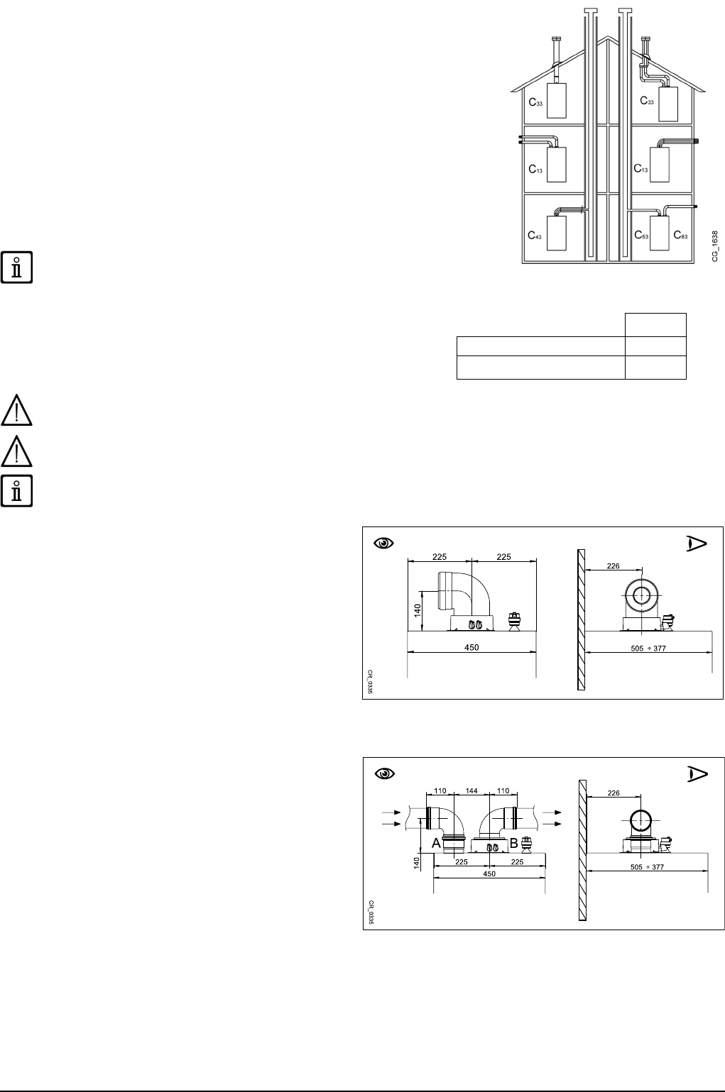
C13, C33 The terminals for separate ues must be tted inside a 50 cm square. Detailed
instructions are provided with the individual accessories.
C53 Do not t the ue and air duct terminals on opposite walls of the building.
C63 The maximum pressure drop ΔP of the ducts must not exceed the values indicated
in table 1A. The ducts must be certied for this specic use and for a temperature in
excess of 100°C. The ue terminal must be certied to EN 1856-1.
C43, C83 The ue terminal or ue duct must be suitable for the purpose.
For optimal installation, the accessories supplied by the manufacturer should
be used.
TABLE 1A
If the ue and air ducts installed are not supplied by our company, make sure they
are certied for the type of use and have a maximum pressure drop as indicated in
the table to the side.
∆P (Pa)
1.35 MP 160
1.50 MP - 1.60 MP - 1.70 MP 270
To optimise operating safety, make sure the ue ducts are rmly xed to the wall with suitable brackets. The brackets must be
positioned over the joints at a distance of approximately 1 metre from one another.
Make sure there is a minimum downward slope of 5 cm per metre of duct towards the boiler.
SOME OUTLET DUCT INSTALLATION EXAMPLES AND THEIR RELATIVE MAXIMUM LENGTHS ARE SHOWN IN ANNEX
"SECTION" D AT THE END OF THIS MANUAL.
10.1 CONCENTRIC DUCTS
This type of duct is used to discharge exhaust fumes and draw
combustion air both outside the building and if a LAS ue is
tted. The 90° coaxial bend allows the boiler to be connected
to a ue-air duct in any direction as it can be rotated by 360° It
can also be used as a supplementary curve combined with a
coaxial duct or a 45° curve.
If fumes are discharged outside the building, the ue-air
duct must protrude at least 18 mm from the wall to allow an
aluminium weathering surround to be tted and sealed to
avoid water inltrations.
• A 90° bend reduces the total duct length by 1 metre.
• A 45° bend reduces the total duct length by 0.5 metres.
• The rst 90° bend is not included when calculating the maximum available length.
10.2 SEPARATE DUCTS
This type of installation makes it possible to discharge exhaust
fumes both outside the building and into single ue ducts.
Comburent air can be drawn in at a different location from that
of the ue terminal. The accessory splitting kit comprises a ue
duct adaptor (80) (B) and an air duct adaptor (A). For the air
duct adaptor, t the screws and seals previously removed from
the cap.
The 90° bend is used to connect the boiler to the inlet and
outlet ducts, adapting them to various requirements. It can also
be used as a supplementary curve combined with a duct or a
45° bend.
• A 90° bend reduces the total duct length by 0.5 metres.
• A 45° bend reduces the total duct length by 0.25 metres.
• The rst 90° bend is not included when calculating the maximum available length.
7221369.01 (1-03/15) 32
INSTALLER Section (en)
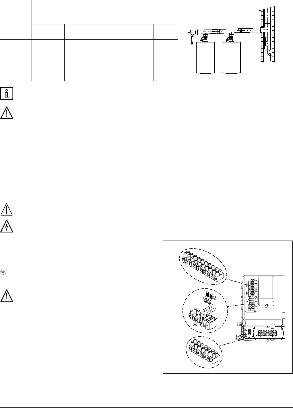
10.3 CASCADE DUCTS
This type of duct evacuates the products of combustion of more than one boiler in a cascade connection through a shared fumes
collector. The collector may only be used to connect the boilers to the ue duct. Available diameters are: Ø125 mm - Ø160 mm
and Ø200 mm. A range of accessories is available on request.
TABLE 1B
BOILER
MODEL
MAXIMUM NUMBER OF BOILERS IN
CASCADE CONNECTION
PARAMETER
P60(a)
Revs/min (rpm) at
minimum Power
Ø125 mm
(200 kW Max)
Ø160 mm
(250 kW Max)
Ø200 mm
(500 kW Max)
G20 G31
1.35 5 7 12 1700 1700
1.50 4 5 10 1700 1700
1.60 3 4 9 1620 1620
1.70 2 3 7 1470 1470
In this outlet typology, a fumes clapet valve (no-return valve), Ø 80/110 mm, must be tted to each boiler. Change the
parameter P60 as shown in table 1B following the procedure described in chapter 14.
The fumes duct must be calculated by a qualied technician during the system design stage, as required by current regulations.
11. ELECTRICAL CONNECTIONS
This machine is only electrically safe if it is correctly connected to an efcient earth system in compliance with current safety
regulations. Connect the boiler to a 230V single-phase earthed power supply using the supplied three-pin cable, observing correct
Live-Neutral polarity.
Use a double-pole switch with a contact separation of at least 3 mm.
When replacing the power supply cable, t a harmonised “HAR H05 VV-F” 3x0,75 mm
2
cable with a maximum diameter of 8 mm.
To access the terminal block, remove the front boiler panel (xed with two screws at the bottom), turn the control box downwards
and access terminal blocks M1, M2, M3, used for the electrical connections, after removing the protective cover. The 3.15 A fast-
blowing fuses are incorporated in the power supply terminal block (to check and/or replace the fuse, pull out the black fuse carrier).
SEE WIRING DIAGRAM IN ANNEX "SECTION" B AT THE END OF THIS MANUAL
Make sure that the overall rated power input of the accessories connected to the appliance is less than 2A. If it is higher, install
a relay between the accessories and the electronic board.
The connections in terminal blocks M1- M3 are high voltage (230 V). Before making connections, make sure the appliance is
disconnected from the power supply. Respect the input polarity on terminal block M1: L (LINE) - N (NEUTRAL).
TERMINAL BLOCK M1
(L) = Live (brown)
(N) = Neutral (light blue).
= Earth (yellow-green).
(1) (2) = contact for Room Thermostat.
Put back the jumper on terminals 1-2 of boiler terminal block
M1 if the room thermostat is not used or if the Remote Control,
supplied as an accessory, is not installed.
TERMINAL BLOCK M2
Terminals 1 (back-lighting) - 2 (earth) - 3 (+12V): connection to the
Remote Control (low voltage) supplied as an accessory.
Terminals 4 - 5 (common): External Probe connection (supplied as
an accessory)
Terminals 6 - 5 (common): 2nd Auxiliary Probe (probes for solar
plant, cascade system, zone system, etc.).
Terminals 7 - 5 (common): 1st Auxiliary Probe (probes for solar
plant, cascade system, zone system, etc.).
Terminals 9-10: storage boiler sensor connection.
Terminal 8: not used.
33
INSTALLER Section (en)
7221369.01 (1-03/15)
TERMINAL BLOCK M3
Terminals 1 - 3: not used.
Terminal 4 - 5: storage boiler pump connection.
Terminal 6 - 7: system heating pump connection (external downline from hydraulic separator).
If the appliance is connected to an underoor system, install a limit thermostat to prevent the latter from overheating.
Use the relative cable grommets at the bottom of the boiler to thread the cables through to the terminal blocks.
A 250Vac/250Vac relay with a minimum current rating of 16A and able to withstand a starting current of above 100A is
required to connect the external pumps.
11.1 CONNECTING THE ROOM THERMOSTAT
The connections in terminal block M1 are high voltage (230 V). Before making connections, make sure the appliance is
disconnected from the power supply. Respect polarity L (LIVE) - N (NEUTRAL).
To connect the Room Thermostat to the boiler, proceed as
described below:
• Switch off the boiler;
• Access the terminal block M1;
• Remove the jumper from the ends of contacts 1-2 and
connect the wires of the volt free Room Thermostat;
• Switch on the boiler and make sure the Room Thermostat
works correctly.
11.2 ACCESSORIES NOT INCLUDED IN THE SUPPLY
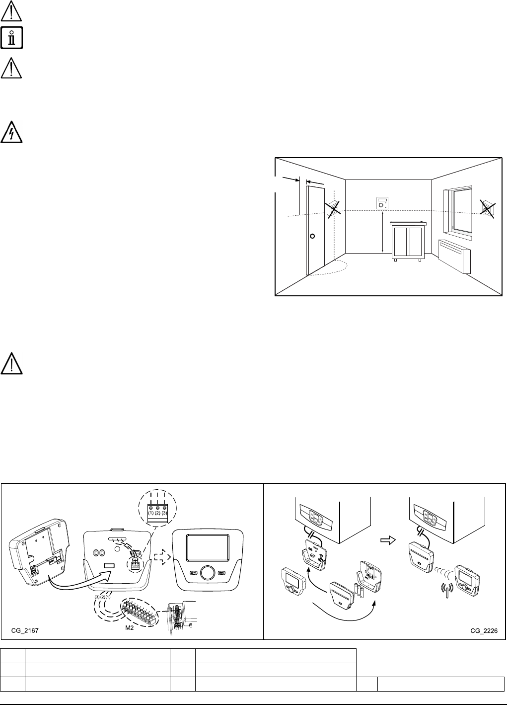
11.2.1 REMOTE CONTROL
The wire (1) from the boiler terminal block M2 powers the display backlighting (12 V). It is not necessary to connect this wire to
make the Remote Control work.
To operate the boiler with the Remote Control mounted on the wall, purchase accessory A supplied with the base A1. Also see
the mounting and operation instructions supplied with the kit A. Proceed as follows:
• Switch off the boiler.
• Pass the three wires from the boiler terminal block M2 through the hole in the base A1 to apply to the wall.
• Connect wires 1-2-3 of the boiler terminal block M2 to terminals (1)-(2)-(3) of the base terminal block A1 respectively.
• Fix the base A1 to the wall using the expansion grips and screws supplied with the accessory.
• Apply the Control Panel A to the base xed to the wall, taking care not to apply excessive force.
• Power the boiler making sure that the Remote Control lights up.
A1
A
A - A1
A
A1
A1
A
B
B1
B
B1
A
Control Panel
A1 Base for wall-mounted Control Panel
B Led interface accessory B1 Base for Led interface accessory
(1) Display backlighting +12V (2) Earth connection (3) Power input/Signal +12V
Min. 200 mm
1500mm
7221369.01 (1-03/15) 34
INSTALLER Section (en)
Use the Remote Control to set the programmable timer for heating and DHW. See the instructions supplied with the accessory.
SETTING PARAMETERS USING THE REMOTE CONTROL
SYMBOLS FOR REMOTE CONTROL
Turn knob B Display shows
Press knob B Press button A and knob B together
Press button A or C Press buttons A and C together
KEY TO FIGURE MENU
1
Enduser
3
Engineer
2
Commissioning
4
OEM
ALL MODIFIED PARAMETERS SHOULD BE NOTED
DOWN IN THE TABLE AT THE END OF THIS MANUAL.
The following procedure is used to access the four boiler
programming menus:
• from the main menu C.
•
A and C (hold down for approx. 6 seconds)
B menu 1-2-3-4 (see gure to side and key).
•
C to go back one menu at a time to the main menu.
When the Control Panel is wall-mounted enable the room sensor and ow temperature modulation as follows:
A) ROOM SENSOR
• Access menu 2.
•
B Operator unit B to conrm.
•
B programme row 40 (Used as) B.
•
B (anti-clockwise) Room unit 1 B to conrm (the room sensor is now active).
•
C to return to the previous menu then B Conguration B.
•
B programme row 5977 (Function input H5) then B to conrm.
•
B None B to conrm.
For correct operation of the environment unit during the reduced time band it is necessary to set the parameter 5977 = "none".
B) FLOW TEMPERATURE MODULATION
To set ow temperature modulation, disable parameter 742 (HC1). Proceed as follows:
• Access menu 2.
•
B Temps / mode CH1 B to conrm B 742 (Flow temp setpoint room stat) B to conrm.
•
B (anti-clockwise) "---" then B to conrm.
If, when turning the knob B on the main menu, the display visualises the boiler ow temperature instead of the ambient
temperature, parameter 742 has not been set correctly.
After every system conguration (e.g.: solar combination, connection an external storage boiler, etc.) perform the following
procedure to update the boiler board to the new conguration:
• Access menu 2 as indicated at the beginning of this section.
•
B Conguration B B programme row 6200 then B.
•
B Yes then B to conrm.
ZONE SYSTEM WITH INSTALLATION OF THE REMOTE CONTROL
The electrical connection and the adjustments required to manage a system divided into zones with use of the Remote Control
differs according on the accessories connected to the boiler. To install and congure, see the instructions of the Expansion
Module supplied as an accessory.
ADJUSTING THE TEMPERATURE OF THE HIGH TEMPERATURE HEATING SYSTEM
To avoid frequent starting and stopping, raise the minimum temperature setpoint of the boiler in the heating mode by setting
parameters 740, to not less than 45°C, using the procedure described in point B.

35
INSTALLER Section (en)
7221369.01 (1-03/15)
TEMPERATURE ADJUSTMENT ON LOW TEMPERATURE HEATING SYSTEM
For a low temperature system (such as underoor heating), reduce the maximum CH temperature setpoint on the boiler by setting
parameter 741 (point B) to a value not greater than 45°C.
11.2.2 EXTERNAL SENSOR
To connect this accessory, see gure to side (terminals 4-5)
and the instructions supplied with the sensor.
With the External Sensor connected, on the boiler
control panel move the set climate curve Kt in parallel (see
annex "SECTION" E and parameter P03 in the table in section
14). To increase room temperature press +, to decrease press
-.
SETTING THE "Kt" CLIMATE CURVE
To set the required kt climate curve, proceed as follows:
• Access the menu as described in section 14.
• Select parameter P03.
• Select the climate curve from among those available, see the curve chart in annex "SECTION" E at the end of this manual
(the preset curve is 1.5).
KEY TO CURVE CHART Kt - "SECTION" E
Flow temp Outside temp
11.2.3 HEATING SYSTEM PUMP
Install the system pump downline from the hydraulic separator. Choose the pump according to the required system capacity/head
characteristics (see annex "SECTION" F).
A 250Vac/250Vac relay with a minimum current rating of 16A and able to withstand a starting current of above 100A is
required to connect the external pumps.
11.2.4 EXTERNAL STORAGE BOILER
The boiler can be electrically connected to an external storage boiler. A diagram of the hydraulic connection of the external storage
boiler is shown in annex "SECTION" F. Connect the storage boiler pump to terminals 4-5 of the M3 terminal block (see annex
"SECTION" B). Install the storage boiler downline from the hydraulic separator. Use the sensor supplied as an accessory and
connect it to terminals 9-10 of terminal block M2 (see annex "SECTION" B). Make sure that the exchange capacity of the storage
boiler coil is appropriate for the power of the boiler.
A 250Vac/250Vac relay with a minimum current rating of 16A and able to withstand a starting current of above 100A is
required to connect the external pumps.
EXTERNAL SYSTEM MANAGEMENT MODULES
The boiler can independently manage up to three heating circuits by using external accessories such as room units, remote
controls and external modules (AGU 2.550 and AVS 75). The boiler electronics also comprises a wide range of functions for
personalising and managing various system types. To assure correct system operation, a number (from 1 to 3) must be assigned
to each accessory in order to allow the boiler board to recognise it. Consequently, carefully read the instructions provided with the
accessories.
11.2.5 MIXED ZONES ("SECTION" F)
A mixed zone can be managed using the AVS75 external module, supplied as an accessory. This accessory can manage: a zone
pump, a mixing valve, a temperature sensor, a limit thermostat and a room thermostat. To connect the components and adjust the
system read the manual provided with the accessory.
11.2.6 BOILERS IN A CASCADE CONNECTION ("SECTION" F)
The AVS75 external unit, supplied as an accessory, is used to manage a heating system with up to 16 boilers connected in a
cascade arrangement and a possible separate storage boiler providing domestic hot water. This accessory, connected to one of
the cascade boilers, can directly control the circuit components up to a maximum of 3 independent relay outlets, 2 temperature
sensors, 1 high voltage limit thermostat connector and one 1 control input (e.g.: room thermostat). The system also requires an
OCI 345 interface on each boiler comprising in the cascade arrangement. To adjust boiler parameters see section "PARAMETER
SETTINGS". To connect the components and adjust the system read the manual provided with the accessory.
11.2.7 SOLAR PLANT ("SECTION" F)
Use the AGU 2.550 external unit, supplied as an accessory, to manage a solar plant. To connect the plant, see the instructions
supplied with the accessory.
THE HYDRAULIC DIAGRAMS OF THE CASES DESCRIBED CAN BE CONSULTED IN ANNEX "SECTION" F AT THE END OF
THIS MANUAL
7221369.01 (1-03/15) 36
INSTALLER Section (en)
12. INITIAL IGNITION - SPECIAL FUNCTIONS
When the boiler is powered up, the code “311” appears on the display and the boiler is ready for “initial ignition”.
Follow the procedure “GAS EXTRACTION FUNCTION” as described in the section below and enable programme 312.
After this operation, the boiler is ready to ignite the burner.
During this phase it is recommended to keep the pressure in the system at a value between 1 and 1.5 bar.
12.1 SYSTEM GAS EXTRACTION FUNCTION
This function is used to facilitate the elimination of the air inside the heating circuit when the boiler is rst installed or after
maintenance when the water is drained from the primary circuit.
To enable the system gas extraction function press buttons together for 6 seconds. When the function is active, On
appears on the display for a few seconds, followed by programme row 312.
The electronic board will activate a pump on/off cycle lasting 10 minutes. The function will automatically stop at the end of the
cycle. To manually exit this function, press the above buttons together for 6 seconds once again.
12.2 CALIBRATION FUNCTION
To calibrate the gas valve, proceed as follows:
• Press buttons and together for at least 6 seconds. When the function is enabled, the displays shows “On” for a few
seconds followed by programme row “304” alternated with the % of boiler power.
• Press
to gradually adjust power (sensitivity 1%).
• To exit press both buttons together for at least 6 seconds, as described in point one
Press to display the instantaneous ow temperature for 15 seconds.
12.3 CHIMNEY SWEEPER
When this function is enabled, the boiler generates maximum heating power. To enable the function, proceed as follows:
• press together for 6 seconds. The display shows "303" alternated with the power output of the boiler.
• Press
and to adjust boiler power 1=minimum, 2=maximum DHW, 3=maximum heating.
• To interrupt the function repeat the procedure described in point one.
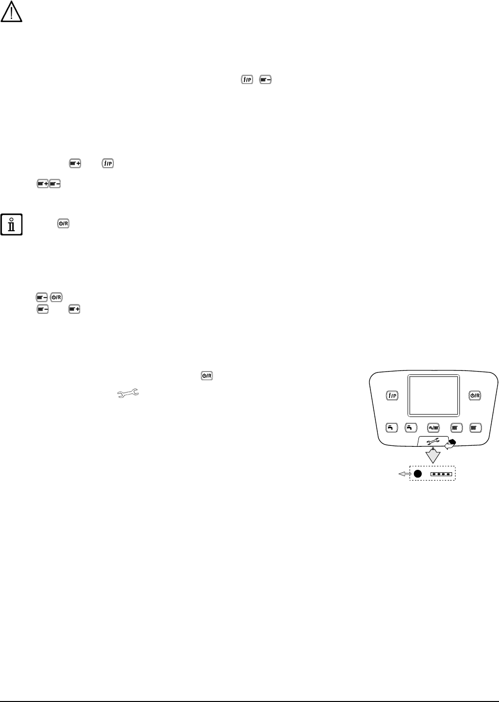
13. FAULTS THAT CANNOT BE RESET BY THE USER
In case of FAULTS that cannot be reset by pressing (such as E151 or exceeding 5 manual
RESET attempts by the user) RESET the board by pressing the black button ( R) located
under the rubber cap (symbol ) of the front control panel (gure to side).

37
INSTALLER Section (en)
7221369.01 (1-03/15)
14. PARAMETERS SETTING
To programme the parameters of the boiler electronic board, proceed as follows:
• Press together and hold them down for 6 seconds until programme row “P02” appears on the display alternated with
the set value (°C);
• Press
and hold down for 6 seconds until "On" appears on the display. Release the button and "P01" appears on the display;
• Press
to scroll the list of parameters;
• Press
, the value of the selected begins ashing, press to change the value;
• press
to conrm the value or press to exit without saving.
Further information concerning the parameters listed in the following table are supplied together with the required
accessories.
(a) (b) ZONE 1 HEATING PARAMETERS (main zone)
Factory
setting
Minimum Maximum
P01 700 *Operating mode (0=Frost Protection, 1=Timed, 3=T.comfort) - 3 0 3
P02 712 *Reduced ambient temperature °C 16 4 35
P03 720 *“Kt” curve slope - 1,5 0,1 4
P04 721 *“Kt” curve drift - 0 - 4,5 4,5
P05 726 *“Kt” curve adaptation (0=off) - 1 0 1
P06 740 Flow temperature setpoint (minimum value) °C 25 8 80
P07 741 Flow temperature setpoint (maximum value) °C 80 25 80
P08 742 *Enable modulating temperature if set = “---” °C 80 25 80
P09 750 *Room inuence (“---” = disabled) % 50 1 100
P10 834 *Opening/Closing speed of mix valve S 30 30 873
ZONE2 HEATING PARAMETERS (with accessory Expansion Unit)
P11 1000 *Operating mode (0= Frost Protection, 1=Timed, 3=T.comfort) °C 3 0 3
P12 1010 *Comfort room temperature °C 20 4 35
P13 1012 *Reduced room temperature °C 16 4 35
P14 1020 *“Kt” curve slope - 1,5 0,1 4
P15 1021 *“Kt” curve drift - 0 - 4,5 4,5
P16 1026 *“Kt” curve adaptation (0=off) - 1 0 1
P17 1040 Flow temperature setpoint (minimum value) °C 25 8 80
P18 1041 Flow temperature setpoint (maximum value) °C 80 25 80
P19 1042 *Enable modulating temperature if set = “---” (ow temp. setpoint if P63=0) °C 80 25 80
P20 1050 *Room inuence (“---” = disabled) % 50 1 100
P21 1134 *Opening/Closing speed of mix valve s 30 30 873
DHW PARAMETERS
P22 1620
Operating mode in DHW (with Remote Control)
- 2 0 20=always enabled, 1=according to hourly heating programme,
2= according to hourly DHW programme.
P23 1640
Anti-legionella function Disabled
- 0 0 1
0=disabled, 1=periodic (depending on P24)
P24 1641
Periodic anti-legionella function enable (only if P23 =1)
- 7 1 7
1=daily, 2..6=intervals of 2..6 days, 7=once a week
P25 1663 Circulation temperature setpoint (additional DHW pump) °C 45 8 80
P26 5470 Preheating time for DHW circuit (1=10’ -- 144=1440’) min 0 0 144
BOILER PARAMETERS
P27 2243 Minimum boiler off time min 3 0 20
P28 2217 Frost Protection setpoint °C 5 -20 20
P29 2250 Pump post-circulation time min 3 0 240
P30 2441 Max. fan speed (heating) rpm xxx 0 8000
P31 2455 Minimum boiler off differential °C 5 0 20
P32 2720 Not used (Do NOT change this parameter) - 0 0 1
P33 2721 Not used (Do NOT change this parameter) - 1 1 2
SOLAR PLANT PARAMETERS (with accessory Expansion Unit)
P34 3810 Temperature - on differential °C 8 0 40
P35 3811 Temperature - off differential °C 4 0 40
P36 3830 Pump start function (“---” = disabled) min --- 5 60
P37 3850 Solar panel manifold overheating protection (“---“ = disabled) °C --- 30 350
P38 5050 DHW boiler tank charging temperature max °C 65 8 95
P39 5051 Maximum temperature of storage tank °C 90 8 95
7221369.01 (1-03/15) 38
INSTALLER Section (en)
CONFIGURATION
P40 5700 Not used (Do NOT change this parameter) - --- --- ---
P41 5710 Zone 1 heating circuit (1=enabled) - 1 0 1
P42 5715 Zone 2 heating circuit (1=enabled) - 0 0 1
P43 5730 DHW sensor (1=Tank sensor, 2=Thermostat, 3=instantaneous sensor) 1 1 3
P44 5890 Not used (Do NOT change this parameter) - 33 0 43
P45 5931 *BX2 sensor input (rst auxiliary sensor – section 11) - 0 0 19
P46 5932 *BX3 sensor input (second auxiliary sensor – section 11) - 0 0 19
P47 5977 *Input H5 (multifunction input – 18=Room thermostat) - 18 0 32
P48 6020 *Conguration of accessory Expansion Unit - 0 0 7
P49 6024 Input EX21 module 1 (conguration of HC Safety Thermostat) - 0 0 1
P50 6046 Input H2 module 1 (multifunction input) - 0 0 58
P51 6097 Sensor type collector (1= NTC, 2= Pt 1000) - 2 1 2
P52 6110 Building time constant (depending on the insulations of the building) h 15 0 50
P53 6220 Software version - --- 0 99
P54 6600 LPB device address (BUS connection) - 1 16
P55 6601 LPB segment address (BUS connection) - 0 14
P56 6640 Clock time source - 0 3
MAINTENANCE
P57 7045 Time after maintenance month xxx 0 240
P58 6704 View/Hide secondary fault internal code (0=no) - 1 0 1
BURNER CONTROL
P59 9512 Required ignition speed rpm xxx 0 8000
P60 9524 Required minimum operating speed (low speed) rpm xxx 0 8000
P61 9529 Required maximum operating speed (high speed) rpm xxx 0 8000
BOILER CONTROL PANEL PARAMETERS
P62 - Unit of measurement (1=bar, °C – 2=PSI, °F) - 1 1 2
P63 - Control panel operation: (1=central, 0=local) - 1 0 1
P64 - Software version
-
xx 0 999
* see “Accessories not included in supply”
xx: the value depends on the software version xxx : the value depends on the type of boiler
(a): parameters read on the front boiler panel (xed control panel) (b): parameters read on the Remote Control

39
INSTALLER Section (en)
7221369.01 (1-03/15)
.
15. GAS VALVE CALIBRATION
To calibrate the gas valve, enable the calibration function as described in section 12.2 and
carry out the following operations:
1) Calibrating MAXIMUM heat output.
Check that the measured on the ue duct, with the boiler operating at maximum heat
capacity, matches that indicated in table 2 (allowed tolerance +/- 0.5%). If it does not, turn
the adjustment screw (V) on the gas valve. Turn the screw clockwise to decrease the level
of and anti-clockwise to increase it (allowed tolerance +/- 0.2%).
2) Calibrating REDUCED heat output
Check that the measured on the ue duct, with the boiler operating at minimum heat
capacity, matches that indicated in table 2 (allowed tolerance +/- 0.5%). If it does not, turn the
adjustment screw (K) on the gas valve. Turn the screw clockwise to increase the level of
and anticlockwise to decrease it (allowed tolerance +/- 0.2%).
V Gas ow adjustment screw Pi Gas supply pressure tap
K OFFSET adjustment screw
15.1 GAS CONVERSION
When converting from natural gas to propane (LPG), before calibrating the gas valve as described above, replace the venturi
assembly (B) as indicated in the gure. To achieve this, release the gas pipe (xed with clips for models 1.35 - 1.50 -1.60 and
threaded nut G1" for model 1.70) and remove the three screws securing the ange. Afterwards, make sure there are no gas
leaks. Modify the parameters (fan rpm) as indicated in table 2 following the procedure described in section 14.
LUNA DUO-TEC 1.35-1.50-1.60 LUNA DUO-TEC 1.70
TABLE 2
PARAMETERS - rpm
VENTURI
Ø (mm)
GAS NOZZLES
Ø (mm)
CO
2
Min
(%)
CO
2
Max
(%)
Max. CO
(ppm)
P60
**
P30 - P61
**
P59
**
Boiler
model
Min. power Max. power Ignition power
G20 G31 G20 G31 G20 G31 G20-G31 G20 G31 G20 G31 G20 G31 G20/G31
1.35 1500 1500 5000 4800 2300 3000 24
3.7
(n°2)
2.95
(n°2)
*8.5 *9.5 *9.0 *10
< 250
1.50 1500 1500 6650 6400 2300 3000 24
3.7
(n°2)
2.95
(n°2)
*8.5 *9.5 *9.0 *10
1.60 1420 1420 6750 6600 2000 2500 28
4.6
(n°2)
3.45
(n°2)
*9.0 *9.4 *9.0 *10.1
1.70 1270 1270 6450 6100 2100 2500 30
5.3
(n°2)
4.0 (n°2) *8.5 *9.5 *9.0 *10
* CO
2
with cover closed. Without cover (chamber open) the value is less than 0.2%.
* * value read on the boiler front panel display to multiply x 10 (e.g.: 150 corresponds to 1500 rpm)
To simplify calibration of the gas valve, set the “calibration function” directly on the boiler control panel as described in
section 12.2.
For cascade ducts, change the parameter P60 increasing the number of fan revolutions by 200 (see table 1B in chapter 10.3).
7221369.01 (1-03/15) 40
INSTALLER Section (en)
16. ADJUSTMENT AND SAFETY DEVICES
The boiler has been designed in full compliance with European reference standards and in particular is equipped with the following:
• Limit thermostat
Thanks to a sensor placed on the CH ow line, this thermostat interrupts the ow of gas to the burner if the water in the primary
circuit overheats. Under such conditions the boiler is blocked and only after the fault has been eliminated can it be ignited again
by pressing
.
• Exchanger ange thermostat (260°C)
This device is located on the exchanger ange and interrupts the ow of gas to the burner if the front insulation yields and
overheats the exchanger or the ange gasket develops a fault. Press the reset button on the thermostat, eliminate the fault and
then press the reset button on the boiler control panel.
It is forbidden to disable this safety device.
• NTC ue sensor
This device is positioned on the fumes duct. The electronic board stops gas from owing to the burner in case of over heating.
Press
to re-establish normal operating conditions.
The above reset operation is only possible if the temperature is less than 90°C.
It is forbidden to disable this safety device
• Flame ionisation detector
The ame sensing electrode guarantees safety of operation in case of gas failure or incomplete ignition of the main burner. In
these conditions, the boiler blocks. Press
to re-establish normal operating conditions.
• Hydraulic pressure switch
This device allows the main burner to be ignited only if system pressure is higher than 0.5 bars.
• Pump post-circulation
The electronically-controlled pump post-circulation function lasts 3 minutes and is enabled, in the heating mode, if the ambient
thermostat causes the main burner to go out.
• Antifreeze device
The electronic boiler management system includes an "antifreeze" function for the heating and DHW systems which, when ow
temperature falls below 5°C, operates the burner until a ow temperature of 30°C is reached. This function is enabled when the
boiler is switched on, the gas supply is open and the system is correctly pressurised.
• Pump anti-block function
If no heat demand is received in the heating and/or DHW modes for 24 consecutive hours, the pumps will automatically start and
operate for 10 seconds.
• Hydraulic safety valve (heating circuit)
This device is set to 4 bar and is used for the heating circuit. Connect the safety valve to a drain trap. Do not use it to drain the
heating circuit.
• Heating pump pre-circulation
In case of a heat demand in the heating mode, the appliance can pre-circulate the pump before the burner is ignited. This pre-
circulation phase last from a few seconds to a few minutes, depending on the operating temperature and installation conditions.
The functions performed by the adjustment and safety devices are only operative if the boiler is switched on.
17. PUMP CAPACITY/ HEAD
The hydraulic pump is modulating and circulates the water between the boiler and the hydraulic separator.
KEY TO PUMP CHARTS - "SECTION" E
Q RATE OF FLOW
H HEAD
THE PUMP FLOW / HEAD CHARTS CAN BE CONSULTED IN ANNEX "SECTION" E AT THE END OF THE MANUAL.

41
INSTALLER Section (en)
7221369.01 (1-03/15)
18. ANNUAL SERVICING
The service must be performed only by qualied and competent staff in accordance with the Gas safety, Installation and use
regulations. In UK this person need to be approved by the Health and Safety Executive. To optimise boiler efciency, carry out the
following at the annual service:
• Check the appearance and airtightness of the gaskets of the gas and combustion circuits;
• Check the state and correct position of the ignition and ame-sensing electrodes;
• Check the state of the burner and make sure it is rmly xed;
• Check for any impurities inside the combustion chamber. Use a vacuum cleaner to do this;
• Check the gas valve is correctly calibrated;
• Check the pressure of the heating system;
• Check the pressure of the expansion vessel (system);
• Check the fan works correctly;
• Make sure the ue and air ducts are unobstructed;
• Check for any blockages inside the siphon.
Before commencing any maintenance operations, make sure the boiler is disconnected from the power supply. After servicing,
reset the original operating parameters of the boiler if they were changed.
18.1 CLEANING THE CONDESATE TRAP
It is advisable not to use the service cap at the base to empty and clean the siphon. Remove the siphon from inside the boiler
and clean it with a jet of water. Fill the siphon with clean water and put back in place, making sure that it is properly connected.
Do not operate the boiler with empty condense trap to avoid risk of poisoning through the gas combustions.
18.2 CLEANING THE HEAT EXCHANGER FUMES SIDE
Before starting to clean the heat exchanger, wait until the temperature is lower than 40°C and protect all the electric components
against splashes of water.
Proceed as follows to clean the heat exchanger:
• Disconnect the boiler from the mains power supply.
• Close the gas inlet valve.
• Remove the front cover from the boiler.
• Lower the electrical box, ensuring it is protected against contact
with water.
• Disconnect the cables of the ignition electrode, the ame sensing
electrode, and the heat exchanger ange thermostat.
• Remove the fan-mixer-burner-ange assembly, unscrewing the 6
nuts M6 and the connector under the mixer.
• Protect the rear insulating panel (2) against water with a waterproof
lm, available in the cleaning kit.
• Accurately suck up the residue inside the combustion chamber and
remove any scale, using a brush with plastic bristles available in
the cleaning kit.
• Sprinkle the surfaces to be cleaned (1) generously with the
appropriate liquid BX-HT Cleaner or similar using the appropriate
spray bottle and wait 10 minutes (other products may be used,
after consulting the authorised technical assistance service).
Brush without rinsing and apply BX-HT Cleaner again. Let 10 more
minutes pass, then brush again. If the result is not satisfactory,
repeat the operation.
• When cleaning is nished, rinse with water.
• Replace the gasket of the burner support ange.
• To reassemble, proceed in the inverse order, tightening the 6 nuts
of the ange with a torque of 5.5 Nm.
CR_0509
1
2

7221369.01 (1-03/15) 42
INSTALLER Section (en)
18.3 CHECKING THE BURNER
The burner needs no cleaning.
• Check the burner surface for damage, replace the burner if necessary.
• Check the positioning of the ame detection probe.
• Verify that the distance of the ignition electrode is within tolerance as shown in the gure.
• Check that the burner surface insulation in the burner ange it is not damaged otherwise replace it.
Connect the gas supply with a new gasket, open the gas supply and check the boiler for gas leaks using a leak testing spray.
CG_2190
c
CR_051
1
a
b
d
a Flame detection probe
b Ignition electrode
c Burner
d Burner surface insulation
18.4 COMBUSTION PARAMETERS
To measure combustion efciency and the emissions of the products of combustion, the boiler is
tted with two dedicated test points. One connection point is connected to the ue gas discharge
circuit ( A), and allows monitoring of the quality of the combustion products and the combustion
efciency. The other is connected to the combustion air intake circuit ( B), allowing checking of any
recycling of the combustion products in case of coaxial pipelines. The following parameters can be
measured at the connection point on the ue gas circuit:
• temperature of the combustion products;
• oxygen (
) or carbon dioxide ( ) concentration;
• carbon monoxide (
) concentration.
The temperature of the combustion air must be measured on the test point located on the air intake ue (B) by inserting the
measurement sensor by about 80 mm (C).
To enable the " CHIMNEY SWEEP MODE" consult section 12.3.
19. DISMANTLING, DISPOSAL AND RECYCLING
Only qualied technicians are authorised to service the device and system.
Before dismantling the appliance, make sure to have cut out the power supply, closed the gas inlet valve and secured all the boiler
and system connections.
Dispose of the appliance correctly according to the laws and regulations in force. The appliance and accessories cannot be
discarded along with normal household waste.
More than 90% of the materials that make up the appliance are recyclable.
80
AB
C

43
INSTALLER Section (en)
7221369.01 (1-03/15)
20. TECHNICAL SPECIFICATIONS
Model: LUNA DUO-TEC MP+ 1.35 1.50 1.60 1.70
Cat. II2H3P
Gas used - G20 - G31
Rated heat input kW 34,8 46,3 56,6 66,9
Reduced heat input kW 5,1 5,1 6,3 7,4
Rated heat power 80/60°C kW 33,8 45 55 65
Rated heat power 50/30 °C kW 36,6 48,6 59,4 70,2
Reduced heat output 80/60 °C kW 5,0 5,0 6,1 7,2
Reduced heat output 50/30 °C kW 5,4 5,4 6,6 7,8
Rated efciency 50/30 °C % 105,0 105,0 105,0 105,0
Max. water pressure in heating circuit bar 4
Min. water pressure in heating circuit bar 0,5
Temperature range in heating circuit °C 25÷80
Fumes typology - C13 - C33 - C43 - C53 - C63 - C83 - C93 - B23
Coaxial ue duct diameter mm 80/125
Diameter of separate outlets mm 80/80
Max. mass ow rate of ue kg/s 0,016 0,021 0,026 0,031
Min. mass ow rate of ue kg/s 0,002 0,002 0,003 0,004
Max. temperature of ue °C 90 92 96 76
Natural gas supply pressure 2H mbar 20
Propane gas supply pressure 3P mbar 37
Power supply voltage V 230
Power supply frequency Hz 50
Rated power supply W 180 230 230 230
Net weight kg 40 40 40 50
Dimensions - height mm 766
- width mm 450
- depth mm 377 377 377 505
Protection-limit against humidity (EN 60529) - IPX5D
Capacity of boiler circuit (volume of water) l 4 4 5 6
EC certicate Nr. 0085CM0128
CONSUMPTION AT HEAT INPUT Qmax and Qmin
Qmax (G20) - 2H m
3
/h 3,68 4,90 5,98 7,07
Qmin (G20) - 2H m
3
/h 0,54 0,54 0,67 0,78
Qmax (G31) - 3P kg/h 2,70 3,60 4,40 5,20
Qmin (G31) - 3P kg/h 0,40 0,40 0,49 0,57

7221369.01 (1-03/15) 44
INSTALLER Section (en)
21. TECHNICAL PARAMETERS
BAXI LUNA DUO-TEC MP+
1.35 1.50 1.60 1.70
Condensing boiler
Yes Yes Yes Yes
Low-temperature boiler
(1)
Yes Yes Yes Yes
B1 boiler
No No No No
Cogeneration space heater
No No No No
Combination heater
No No No No
Rated heat output
Prated
kW 34 45 55 65
Useful heat output at rated heat output
and high temperature regime
(2)
P
4
kW 33.8 45.0 55.0 65.0
Useful heat output at 30% of rated heat
output and low temperature regime
(1)
P
1
kW 11.2 14.9 18.2 21.5
Seasonal space heating energy efficiency
ƞ
s
% 92 92 92 92
Useful efficiency at rated heat output and
high temperature regime
(2)
ƞ
4
% 87.7 87.7 87.6 87.6
Useful efficiency at 30% of rated heat
output and low temperature regime
(1)
ƞ
1
% 97 97.1 96.8 96.5
Auxiliary electricity consumption
Full load
elmax
kW 0.070 0.080 0.095 0.095
Part load
elmin
kW 0.020 0.020 0.020 0.020
Standby mode
P
SB
kW 0.003 0.003 0.003 0.003
Other items
Standby heat loss
P
stby
kW 0.064 0.064 0.070 0.075
Ignition burner power consumption
P
ign
kW 0.000 0.000 0.000 0.000
Annual energy consumption
Q
HE
GJ
Sound power level, indoors
L
WA
dB 58 62 59 62
Emissions of nitrogen oxides
NO
X
mg/kWh 29 29 31 31
Domestic hot water parameters
Declared load profile
Daily electricity consumption
Q
elec
kWh
Annual electricity consumption
AEC
kWh
Water heating energy efficiency
ƞ
wh
%
Daily fuel consumption
Q
fuel
kWh
Annual fuel consumption
AFC
GJ
(1) Low temperature means for condensing boilers 30°C, for low temperature boilers 37°C and for other heaters 50°C return
temperature (at heater inlet).
(2) High temperature regime means 60°C return temperature at heater inlet and 80°C feed temperature at heater outlet.

45
INSTALLER Section (en)
7221369.01 (1-03/15)
22. PRODUCT FICHE
BAXI LUNA DUO-TEC MP+
1.35 1.50 1.60 1.70
Space heating - Temperature application Medium Medium Medium Medium
Water heating - Declared load profile
Seasonal space heating energy efficiency class
A A A A
Water heating energy efficiency class
Rated heat output
(Prated or Psup)
kW 34 45 55 65
Space heating - Annual energy consumption
GJ
Water heating - Annual energy consumption
kWh
(1)
GJ
(2)
Seasonal space heating energy efficiency % 92 92 92 92
Water heating energy efficiency %
Sound power level L
WA
indoors
dB 58 62 59 62
(1) Electricity
(2) Fuel

7221369.01 (1-03/15) 90
SECTION A
20

91
SECTION A
7221369.01 (1-03/15)
it en
1
Ventilatore Fan
2
Collettore miscela aria-gas Air/gas blend manifold
3
Scambiatore primario Primary exchanger
4
Sonda fumi Flue sensor
5
Convogliatore fumi Flue hood
6
Raccordo scarico fumi coassiale Coaxial ue connector
7
Valvola di sfogo aria automatica Automatic air vent
8
Sonda NTC riscaldamento
(mandata e ritorno)
NTC water heating sensor
(ow and return)
9
Termostato di sicurezza (sovratemperature) Safety overow temperature thermostat
10
Elettrodo di accensione Ignition electrode
11
Elettrodo di rivelazione di amma Flame detection electrode
12
Accenditore Spark generator
13
Venturi Venturi
14
Pompa Pump
15
Valvola di sicurezza idraulica Hydraulic Safety valve
16
Rubinetto di scarico caldaia Boiler drain tap
17
Manometro Pressure gauge
18
Sensore di pressione idraulico Hydraulic Pressure Sensor
19
Valvola gas Gas valve
20
Termostato angia scambiatore Exchanger ange thermostat
A
Attacco sifone scarico condensa Trap condensate drain
B
Attacco ingresso GAS Gas inlet connection
C
Attacco mandata acqua riscaldamento Heating ow connection
D
Attacco ritorno acqua riscaldamento Heating return connection
de es
1
Ventilator Ventilador
2
Sammelrohr Luft-/Gasgemisch Colector de mezcla aire-gas
3
Primär-Tauscher Intercambiador primario
4
Abgasfühler Sonda de humos
5
Abgasleitung Canalizador de humos
6
Koaxiale Abgasleitung Racord conexión humos coaxial
7
Automatisches Entlüftungsventil Válvula de purga aire automática
8
NTC-Fühler Heizung
(Vor- und Rücklauf)
Sonda NTC calefacción
(ida y retorno)
9
Sicherheitsthermostat (Übertemperatur) Termostato de seguridad (sobretemperaturas)
10
Zündungselektrode Electrodo de encendido
11
Flammenüberwachungselektrode Electrodo de detección de llama
12
Zünder Encendedor
13
Venturi Venturi
14
Pumpe Bomba
15
Hydraulisches Sicherheitsventil Válvula de seguridad hidráulica
16
Entleerungshahn Heizkessel Grifo de descarga caldera
17
Druckmesser Manómetro
18
Hydraulikdruckfühler Sensor de presión hidráulico
19
Gasventil Válvula del gas
20
Thermostat des Wärmetauscheransches Termostato brida intercambiador
A
Anschluss Kondenswasser-Auslasssiphon Conexión desagüe condensados
B
Eingangsanschluss GAS Conexión entrada de gas
C
Anschluss Heizwasservorlauf Conexión ida agua Calefacción
D
Anschluss Heizwasserrücklauf Conexión retorno agua Calefacción

7221369.01 (1-03/15) 92
SECTION B
M1
3
2
1
4
5
6
7
8
12
13
14
15
17
16
18
19
11
10
9
X10
X11
X12
X13
X14
X1 X2
X23
X70
X60
X22
X50
X42X41X40
X30X21X20
B
B
V
N
R
C
C
R
R
B
B
C
M
V
N
M
N
C
V
NVMCCC
C
C
N
V
b
a
M
C
G/V
G/V
G/V
G/V
G/V
G/V
G/V
G/V
G/V
G/V
1
15
M
N
P
Y
B
R
L
N
1
2
M
C
G/V
G/V
G/V
N
M
N
C
M
C
M
10
9
8
7
6
5
4
3
2
1
M2
V
V
V
V
V
N
1
2
3
4
5
6
7
M3
R
N
CR_0600
20
21
B
N
R
N
R
V
C
C
R
R
NM
VN
N
R
CM
MC
C
C
G/V
G/V
G/V
G/V
Y
P
NM
C
22
C
C
C
M

93
SECTION B
7221369.01 (1-03/15)
it en de es
1
Fusibili Fuses Schmelzsicherungen Fusibles
2
Alimentazione elettrica 230 V 230 V Power Supply Stromversorgung 230 V Alimentación eléctrica 230 V
3
Termostato Ambiente (TA) Room Thermostat (RT) Raumthermostat (RT) Termostato Ambiente (TA)
4
Sonda mandata riscaldamento Heating ow sensor Vorlauffühler Heizung Sonda impulsión calefacción
5
Sonda ritorno riscaldamento Heating return sensor Rücklauffühler Heizung Sonda retorno calefacción
6
Sensore di pressione Water pressure sensor Drucksensor Sensor de presión
7
Sonda fumi Fumes sensor Abgasfühler Sonda de humos
8
Sonda bollitore sanitario DHW tank sensor Fühler Warmwasserspeicher Sonda calentador ACS
9
Sonda ausiliaria 1 Auxiliary Sensor 1 Hilfsfühler 1 Sonda auxiliar 1
10
Sonda ausiliaria 2 Auxiliary Sensor 2 Hilfsfühler 2 Sonda auxiliar 2
11
Sonda esterna Outdoor sensor Außentemperaturfühler Sonda exterior
12
Controllo Remoto Remote Control FERNBEDIENUNG Control Remoto
13
Pompa Pump Pumpe Bomba
14
Elettrodo di rivelazione amma Flame sensor electrode Flammenüberwachungselektrode Electrodo de detección de llama
15
Elettrodo di accensione Ignition electrode Zündungselektrode Electrodo de encendido
16
Accenditore Igniter Zünder Encendedor
17
Valvola gas Gas valve Gasventil Válvula del gas
18
Termostato di sicurezza Safety Thermostat Sicherheitsthermostat Termostato de seguridad
19
Ventilatore Fan Ventilator Ventilador
20
Pompa circuito di riscaldamento Heating circuit pump Pumpe Heizkreislauf Bomba circuito de calefacción
21
Pompa bollitore sanitario DHW boiler tank pump Pumpe Warmwasserspeicher Bomba calentador ACS
22
Termostato angia scambiatore Exchanger ange thermostat Thermostat des Wärmetauscheransches Termostato brida intercambiador
C
Celeste Blue Hellblau Celeste
M
Marrone Brown Braun Marrón
N
Nero Black Schwarz Negro
R
Rosso Red Rot Rojo
G/V
Giallo/Verde Yellow/Green Grüngelb Amarillo/Verde
V
Verde Green Grün Verde
B
Bianco White Weiß Blanco
G
Grigio Grey Grau Gris
Y
Giallo Yellow Gelb Amarillo
P
Viola Violet Violett Violeta
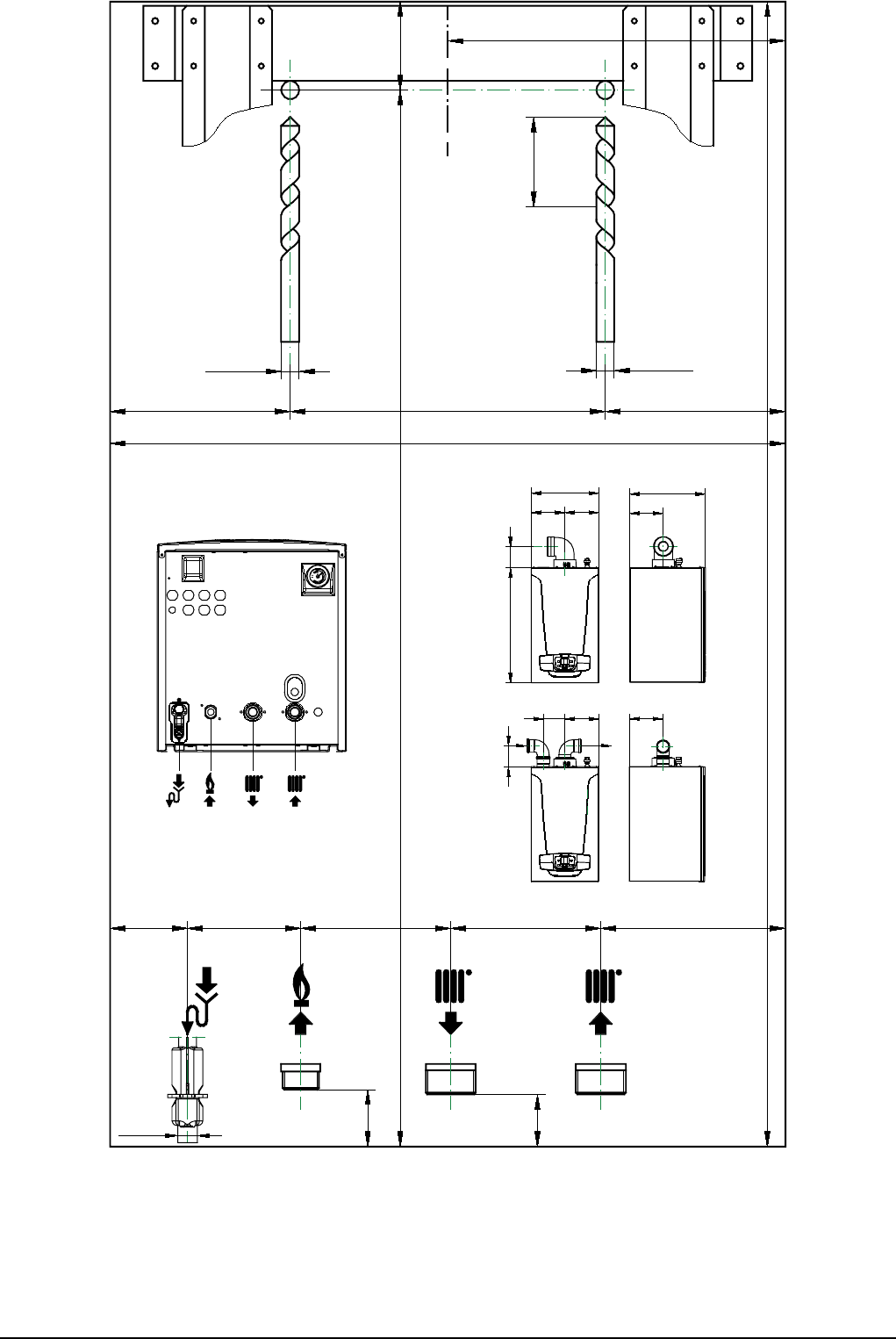
7221369.01 (1-03/15) 94
SECTION C
G 3/4" G 1" G 1"
Ed.1-02/2015
7221122.01
12O
12O
225
120 210 120
704 59
51,5 75,5 100 100 123
35
38
450
763
763 140
225225
450
229
505- 377
225144
140
229
G 3/4" G 1"
G 1"
60
22O

95
SECTION C
7221369.01 (1-03/15)
G 3/4" G 1"
G 1"
95
123100100
CR_0774
75,551,5
43
22
O

7221369.01 (1-03/15) 96
SECTION D
A B
Lmax = 10 m - Ø 80/125 mm
C D
Lmax = 9 m - Ø 80/125 mm
E F
Lmax = 10 m - Ø 80/125 mm
G
Lmax = 8 m - Ø 80/125 mm
H
Lmax = 9 m - Ø 80/125 mm
I
(L1+L2) max = 60 m - Ø 80 mm (1.35 MP)
(L1+L2) max = 60 m - Ø 80 mm (1.50 MP)
(L1+L2) max = 40 m - Ø 80 mm (1.60 MP)
(L1+L2) max = 30 m - Ø 80 mm (1.70 MP)
L1 max = 15 m
L2 max = 20 m m - Ø 80 mm (1.70 MP)
L
L max = 15 m

97
SECTION E
7221369.01 (1-03/15)
MP+ 1.35-1.50 MP+ 1.60
MP+ 1.70
0
1
2
3
4
5
6
7
8
9
10
11
H (mH
2
O)
Q (l/h)
Q (l/h)
0
1
2
3
4
5
6
7
8
9
10
11
0
1
2
3
4
5
6
7
8
9
10
11
Q (l/h)
H (mH
2
O)
H (mH
2
O)
70kW
65kW
55kW
60kW
50kW
45kW
35kW
30kW

7221369.01 (1-03/15) 98
SECTION F
AGU 2.550
CR_0349
CR_0349
AVS 75

99
SECTION F
7221369.01 (1-03/15)
CG_2482
Tmax = 50 °C

7221369.01 (1-03/15)
PARAMETRI MODIFICATI / MODIFIED PARAMETERS /
MODIFIZIERTE PARAMETER / PARAMETROS MODIFICADOS
N° / Nr / Núm.
VALORE / VALUE /
WERT / VALOR
NOTA / NOTE / ANMERKUNG
36061 Bassano del Grappa (VI) - ITALIA
Via Trozzetti, 20
Servizio clienti: tel. 0424-517800 – Telefax 0424-38089
www.baxi.it
