
HAL Id: hal-02053552
https://imt-mines-albi.hal.science/hal-02053552
Submitted on 5 Mar 2019
HAL is a multi-disciplinary open access
archive for the deposit and dissemination of sci-
entic research documents, whether they are pub-
lished or not. The documents may come from
teaching and research institutions in France or
abroad, or from public or private research centers.
L’archive ouverte pluridisciplinaire HAL, est
destinée au dépôt et à la diusion de documents
scientiques de niveau recherche, publiés ou non,
émanant des établissements d’enseignement et de
recherche français ou étrangers, des laboratoires
publics ou privés.
Experimental Study of the injection stretch/blow
molding process
Fabrice Schmidt, Jean-François Agassant, Michel Bellet
To cite this version:
Fabrice Schmidt, Jean-François Agassant, Michel Bellet. Experimental Study of the injection
stretch/blow molding process. Proceeding of the ANTEC ‘97, Society of Plastics Engineers, Apr
1997, Toronto, Canada. �hal-02053552�
EXPERIMENTAL STUDY OF THE INJECTION
STRETCH/BLOW MOLDING PROCESS
Fabrice. M. Schmidt, Ecole des Mines d'Albi Carmaux (FRANCE)
J.F. Agassant CEMEF, Ecole des Mines de Paris (FRANCE)
M. Bellet CEMEF, Ecole des Mines de Paris (FRANCE)
Abstract
The performance of Poly(Ethylene Terephtalate)
bottles produced by the injection stretch/blow molding
process depends on three main variables: the initial
preform shape, the initial preform temperature and the
balance between stretching and blowing rates. In order to
characterize process parameters, experiments have been
performed on a well instrumented mold. In addition,
preform free inflation have been processed and a
simplified model of an air volum free blowing has been
developed.
Introduction
The injection stretch/blow molding process of
PET bottles is a three step process (see Figure 1): first the
PET resin is injected in a tube-shaped preform, then this
amorphous preform is heated above the glass transition
temperature (T
g
80°C) and transfered inside a mold.
Finally the preform is inflated with stretch rod assistance in
order to obtain the desired bottle shape. This study will
deal only with the last step of the process.
The process parameters will induce the thickness
distribution of the bottle as well as the biaxial orientation
and cristallinity, which in turn govern the transparency and
the mechanical properties of the bottle. Thus, in order to
measure process parameters and to characterize the
rheology of the material under biaxial stretching,
experimental work has been conducted on an instrumented
blow molding machine.
A few works refer to the experimental
investigation of the kinematic of the blow or stretch/blow
molding processes (1 to 5). In a recent paper, Haelly and
Ryan (5) have filmed parison free/confined inflation in
blow molding of different polymers using high speed video
camera. In the case of confined parison inflation, they have
designed a transparent acrylic mold. Although this work
represents a great contribution to the analysis of parison
inflation, the technic still remains limited to simple
geometries of mold (high curvatures enhance distorsions of
the view). In addition, the design of a speficic mold for
each blow molding experiment appears to be costly. The
use of contacts sensors at the mold wall which permit to
identify the contact time between the polymer and the mold
seems to be a good compromise.
Instrumented mold of a stretch/blow
molding machine
In order to measure stretch/blow molding
parameters, experiments have been performed on a
properly instrumented mold at SIDEL COMPANY (6). For
the bottle mold and the preform, we have made the choice
of simplified geometries (see Figure 2). The dimensions
are summarized in Table 1. The instrumented mold is
described summarily in figure 3. The displacement of the
stretch rod is controlled and the force exerted on the
stretch rod is recorded versus time using a force sensor.
The blowing pressure is imposed and recorded versus time
using a pressure sensor. Nine contact sensors at the mold
wall permit to identify the contact time between the
polymer and the mold.
The process parameters of the stretch/blow
molding step are refered in Table 2 as well as typical
values. The parameters associated with the stretching stage
are the velocity of the stretch rod
v
c
which is applied until
the preform contacts the bottom of the mold, and Rps the
preblowing delay (Rps is the displacement of the stretch
rod, in millimeter, without inflation pressure). The
parameters associated with the inflation stage are Pps the
maximum pre-blowing pressure (low-pressure) imposed
during a preblowing time tps for initiating the general trend
of the bottle, and Ps the maximum blowing pressure (high-
pressure) which is applied during a blowing time ts in
order to flatten the polymer against the mold wall. The
preblowing flow-rate Qps and the blowing flow-rate Qs are
not measured.
In previous papers (7, 8), we have pointed out, by
plotting the stretching force versus time, that the increasing
part and the decreasing part of the stretching force are
corresponding respectively to the elastic and viscous
response of the PET.

The location of the contact sensors (from n° 1 to
n° 9) on the mold wall is indicated in figure 2. Recorded
contact times versus number of contact sensors are plotted
in figure 4 using the process parameters which are refered
in Table 2. When the preblowing delay Rps is increased
from 1 mm to 40 mm, all the contact times between the
polymer and the mold increase and the contact times are
more homogenous in the central part of the bottle. In
addition, if we plot the measured thickness distribution
versus longitudinal coordinate at the end of the process for
the two values of Rps (see figure 5), we note that an
increase in the preblowing delay induces more material
displacement from the neck to the bottom of the bottle.
Measurement and calculation of the internal
pressure
Let us now study the free inflation of a preform
without stretching rod. The preform (cf. figure 2) is heated
in a silicone oil bath in order to obtain an uniform
temperature distribution, this for three different values of
temperature (T=95°C, 100°C, 105°C). An inflation
pressure p
a
(t) is applied on the internal surface of the
bottle and the differential inflation pressure p
a
(t) =
p
a
(t) -
p
o
(p
o
atmospheric pressure at ambient temperature) is
recorded versus time using a pressure sensor. For each
temperature, free inflations have been filmed using video
camera. In figure 6, different steps of preform free inflation
are presented for T=105°C. In addition, the recorded
differential pressure is plotted versus time for three
different values of temperature (see figure 7). All the
curves are composed of three different parts:
. a first part where the pressure rises to a maximum (less
than 3 bars), during which the polymer is not inflated (the
internal volume of the preform remains constant);
. a second part where the pressure decreases continuously
to a minimum because the internal volume increases;
. the last part of the curve where the pressure increases in
order to force the “strain-hardening” phenomenon of the
material, which in fact is related to the development of
cristallinity under biaxial stretching.
This experiment demontrates that the evolution of
the internal pressure and the inflation of the preform are
highly coupled. It is to be noticed that the recorded internal
pressure is significantly different from a constant
“nominal” pressure. In order to better understand this
pressure evolution, we develop hereafter a simple
thermodynamic model. As sketched in figure 8, we
consider that air, at temperature T
a
, flows in the "control
volume" V
a
(t) at a specific flow-rate q with entry velocity
field w
e
, pressure p
e
and temperature T
e
. The specific
flow-rate q is constant (cf. pre-blowing stage), so it results
in the following relationship between the air mass
m
a
(t) (occupying the volume V
a
(t)) and q:
q
dm
a
dt
cte m
a
t m
o
qt
(1)
where m
o
is the air mass at time t = 0. Using the following
assumptions:
. no heat transfer between the air volume and the
surrounding medium,
. air is an ideal gas,
the global energy balance during the time step dt over the
volume V
a
(t) may be simplified as:
d
dt
Ln(p
a
V
a
)
=
d
dt
Ln(m
a
)
T
e
T
a
(2)
where = 1.4 for the air. It is noteworthy that a very
similar relationship has been determined by G. Louiz (9).
In order to obtain a simplified relationship, we make the
more criticizable assumption T
a
T
e
. Using (1) and m
a
=
a
V
a
, equation (2) reduces to:
p
a
(t)
p
o
=
1
o
m
o
+ qt
V
a
(t)
(3)
where
o
is the air specific mass at time t = 0. Knowing
the increase of volume V
a
(t) (due to parison inflation) ,
this relation should provide the pressure value p
a
(t) .
However, the experimental determination of the specific
flow-rate q is very difficult. In order to overcome this
difficulty, we suggest that q should be determined through
an inflation test at constant volume
V
Erreur !
. Deriving eq. (3) with respect to time, at initial
time t = 0, we obtain :
q =
o
V
o
p
o
dp
a
(t)
dt
t = 0
(4)
Once the specific flow-rate q has been experimentally
determined, it is possible to express the differential
inflation pressure p
a
(t) :

p
a
(t)
p
o
=
V
o
V
a
(t)
1+
t
p
o
dp
a
(t)
dt
t = 0
- 1 (5)
This relationship has been introduced in the
stretch/blow molding finite element code BLOWUP (10)
in which the rheological behavior of the PET is
represented by a viscoelastic constitutive equation of
Oldroyd-B type. For the calculation of p
a
(t) using the
relationship (5), we proceed as follows:
. inflation at a given specific flow-rate of a preform which
has not been heated and measurement of the initial slope of
the recorded pressure curve,
. computation of the initial internal volume of the preform
V
o
,
. computation of the internal volume of the preform V
a
(t)
at each time step and application of (5).
Application of preform free inflation
From the first results of preform free inflation
issued from numerical simulation it appears that the
expansion of the preform and especially the radial
expansion is unlimited. This problem, which is not
observed experimentally, occurs because the strain-
hardening phenomenon of the material is not taken into
account in the numerical model. Strain-hardening is related
to the development of cristallinity under biaxial stretching.
The problem of coupling between microstructural
evolution and thermomechanical history still remains an
open issue. It is not the goal of the present article to
discuss such problems. However, a simple model which is
able to take into account “in a certain sense” the strain-
hardening phenomenon has been tested. The relation
proposed by G’Sell (11) is based on the assumption that
the viscosity depends on the generalized strain. The
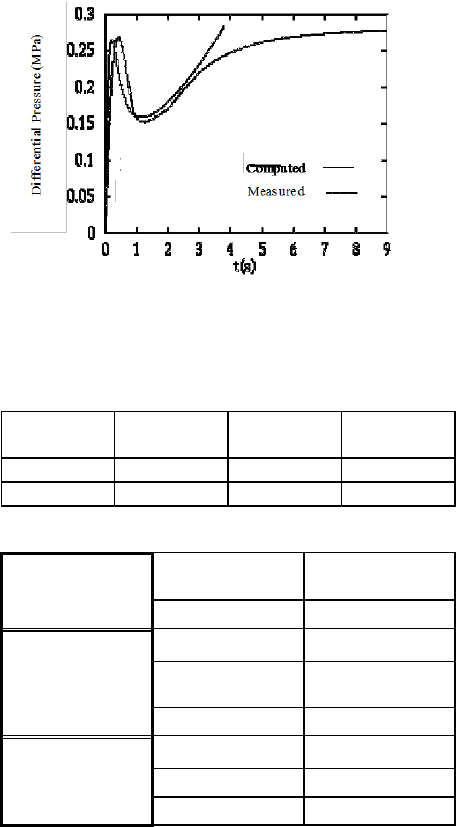
computed differential inflation pressure and the measured
one at T=105 °C are plotted in Figure 9. We note that the
agreement is fair between the two curves except in the last
part. Experiments have shown that anisotropy occurs
during the development of cristallinity. That’s why axial
expansion still continues while radial expansion is blocked.
The proposed model induces isotropic strain-hardening. It
results that the expansion of the bubble is limited in the
same manner in all directions. If the volume of the preform
remains constant, the pressure increases according to the
relation (5).
Conclusion
Experimental work has been conducted on an
instrumented blow molding machine. Process parameters
such as the preblowing delay and the velocity of the stretch
rod have exhibited a significant influence on the thickness
distribution in the final product. In addition, the use of
contacts sensors has permitted to identify the kinematic of
confined preform inflation .
A simplified model of an air volum free blowing
has been developed and introduced in a finite element
code. Due to results issued from numerical simulations, it
appears that coupling between microstructural evolution
and thermomechanical history should be the next issue of
this work.
Acknowledgments
This research was supported by SIDEL COMPANY and
the French "Ministère de la recherche" (MRT n° 90A 136)
References
(1) Kamal M.R., Tan V., Kalyon D.M., "Measurement and
Calculation of Parison Dimensions and Bottle Thickness
Distribution During Blow Molding", Polym. Eng. Sci., 21,
pp. 331-338 (April), 1981
(2) Ryan M. E. et Dutta A., "The dynamics of Parison Free
Inflation in Extrusion Blow Molding ", Polym. Eng. Sci.,
22, pp. 569-577, 1982
(3) Dutta A. et Ryan M. E., "Confined Parison Inflation
Behavior of a High-Density Polyethylene", Polym. Eng.
Sci., 24, pp. 1232-1239, 1984
(4) Cakmak M. , White J. L., "An Investigation of the
Kinematics of Stretch Blow Molding Poly(Ethylene
Terephtalate ) Bottles" , J. Appl. Polym. Sc., 30, pp. 3679-
3695 , 1985
(5) Haessly W. P. et Ryan M. E., Polym. Eng. Sci., 33, pp.
1279-1287, 1993
(6) Thomas L., "Vérification expérimentale d'une thèse sur
la modélisation du soufflage avec bi-orientation de
bouteilles en P.E.T.", (in French), Report, Ecole des mines
de Douai, 1991
(7) Schmidt F. M., Agassant J. F., Bellet M. and Denis G.,
"Numerical Simulation of Polyester Stretch/Blow Molding
Process", Numiform 92, Proc. 4th Int. Conf. on Numerical
Methods in Industrial Forming Processes, Balkema, pp.
383-388, September 1992

(8) F. M. Schmidt, J. F. Agassant, M. Bellet and L.
Desoutter, "Viscoelastic Simulation of P.E.T Stretch/Blow
Molding", J. of Non-Newt. Fluid Mech., 64 (1996), 19-42
(9) Louiz G., "Injection-soufflage de bouteilles en
polyseter", (in French), Report, Ecole des Mines de Paris,
1989
(10) F. Schmidt, "Etude expérimentale et modélisation du
procédé d’injection/soufflage bi-orientation en cycle froid
de bouteilles en P.E.T.”, Thesis, in French, Ecole des
Mines de Paris, 1995
(11) G'Sell C., "Instabilités de déformation pendant
l'étirage des polymères solides", in French, Revue Phys.
Appl., 23, pp. 1085-1101, 1988
Figures with captions
Figure 1: Description of the injection stretch/blow molding
process
Figure 2: Geometry of the bottle mold
and initial preform

Figure 3: Description of the instrumented mold of a
stretch/blow molding machine
Figure 4: Contact times versus
number of contact sensors
Figure 5: Thickness distribution
at the end of the process
t = 2.79 s
t = 3.1 9
s
t = 3.75 s
t = 5.3 5 s
Figure 6: Preform free inflation (T=105°C)
Figure 7: Differential inflation pressure versus time
p
V(t)
Q
W
w
a
e
e
Figure 8: Volum free blowing
at a constant flow rate
Figure 9: Measured and computed differential inflation
pressure versus time (T=105°C)
Tables with captions
Length
(mm)
Inner radius
(mm)
External
radius (mm)
Preform
125
9.275
13.025
Bottle mold
310
44.3
44.3
Table 1: Dimensions of the bottle mold and the preform
Stretching
stage
v
c
(mm/s)
500
R
ps
(mm)
1
P
ps
(Pa)
5.10
5
Preblowing
stage
D
ps
(s)
0.3
Q
ps
(kg/s)
-
P
s
(Pa)
40.10
5
Blowing stage
D
s
(s)
1.5
Q
s
kg/s)
-
Table 2: Process parameters
Keywords
stretch/blow molding; experimental
investigations; air volum free blowing model;
calculation of internal pressure
