
AMBIENT AIR MONITORING AND QUALITY
ASSURANCE/QUALITY CONTROL GUIDELINES
National Air Pollution Surveillance Program
PN 1599
ISBN 978-1-77202-056-4 PDF
© Canadian Council of Ministers of the Environment, 2019
i
NOTE TO READERS
The Canadian Council of Ministers of the Environment (CCME) is the primary minister-led
intergovernmental forum for collective action on environmental issues of national and
international concern.
This document contains guidance related to air quality monitoring procedures at National Air
Pollution Surveillance (NAPS) sites across the country and replaces the Ambient Air Monitoring
Protocol for PM
2.5
and Ozone: Canada-wide Standards for Particulate Matter and Ozone (CCME
2011) and the manual titled National Air Pollution Surveillance Network Quality Assurance and
Quality Control Guidelines (EC 2004). It provides recommendations and establishes minimum
requirements to ensure that data collected by the NAPS Program are of known quality, defensible,
and comparable across Canada.
This document was developed for the Air Management Committee, by staff of the Analysis and
Air Quality Section of Environment and Climate Change Canada. CCME would like to thank all
individuals that participated in completing this document and more specifically the following
working group members representing provincial and territorial governments: Melynda Bitzos and
Mike Noble (Ontario), Eric Blanchard (New Brunswick), Fran Di Cesare (Nova Scotia), Chris
Gray (Saskatchewan), Jany McKinnon (Québec) and Ryan Wiederick (British Columbia), and
Christian Vezina for his contribution as an external reviewer.

ii
TABLE OF CONTENTS
NOTE TO READERS ..................................................................................................................... i
LIST OF TABLES .......................................................................................................................... v
LIST OF FIGURES ....................................................................................................................... vi
ACRONYMS AND ABBREVIATIONS ..................................................................................... vii
GLOSSARY ................................................................................................................................ viii
1.0 INTRODUCTION .............................................................................................................. 1
2.0 NAPS PROGRAM AND MONITORING OBJECTIVES................................................. 1
2.1 NAPS Monitoring Objectives ......................................................................................... 2
3.0 NAPS PROGRAM ORGANIZATION .............................................................................. 3
3.1 NAPS Program Operation ............................................................................................... 3
Environment and Climate Change Canada ................................................................. 3
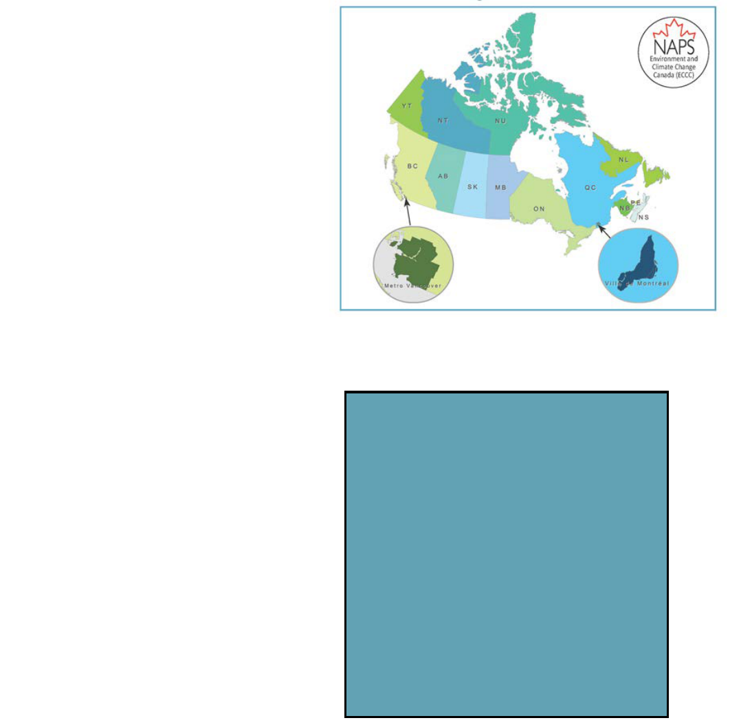
Provincial and Territorial Governments, Metro Vancouver and Montréal ................. 4
4.0 DATA QUALITY OBJECTIVES (DQO) .......................................................................... 4
5.0 TRAINING ......................................................................................................................... 7
6.0 DOCUMENTATION AND RECORDS ............................................................................ 8
6.1 Network Quality Assurance Plan (NQAP) ...................................................................... 9
6.2 Site Classification ......................................................................................................... 11
6.2.1 Class 1: Urbanization ................................................................................................ 11
6.2.2 Class 2: Neighbourhood Population ......................................................................... 12
6.2.3 Class 3: Local Land Use ........................................................................................... 12
6.2.4 Class 4: Site Type ..................................................................................................... 13
6.3 Equipment Information and Inventory.......................................................................... 17
6.4 Standard Operating Procedures (SOP) for the NAPS Program ................................... 17
7.0 NETWORK DESIGN AND SITE LOCATION .............................................................. 17
7.1 Network Design ............................................................................................................ 20
7.1.1 Core Sites .................................................................................................................. 20
7.1.2 Program-specific Sites .............................................................................................. 23
7.1.3 Pollutant-specific Sites.............................................................................................. 25
7.2 Site Location Selection Process ...................................................................................... 26
7.2.1 Prioritizing Monitoring Objectives ........................................................................... 27
7.2.2 Spatial Scales of Representativeness ........................................................................ 27
7.2.3 Site Types.................................................................................................................. 30
7.2.4 Population Density .................................................................................................... 31
7.2.5 Local Land Use ......................................................................................................... 32
8.0 MONITORING STATION DESIGN ............................................................................... 32
8.1 Station Design ............................................................................................................... 32
8.2 Sampling Inlet System Design ....................................................................................... 32
8.2.1 Sampling Inlet Placement ......................................................................................... 33
8.3 Manifold Design ........................................................................................................... 35
iii
8.3.1 Residence Time (Rt) Calculations ............................................................................ 37
8.3.2 Pressure Drop Measurements ................................................................................... 37
9.0
MONITORING, SAMPLING
AND ANALYTICAL METHODS ..................................... 37
9.1 Continuous Methods ..................................................................................................... 38
9.2 Integrated Methods ....................................................................................................... 41
9.3 New Instrument Pre-deployment Testing and Inspection ............................................. 43
9.3.1 Continuous Gas Analyzers ........................................................................................ 43
9.3.2 PM Instruments ......................................................................................................... 43
10.0 ROUTINE OPERATION ................................................................................................. 43
10.1 Routine Inspection and Maintenance Checks ................................................................ 43
10.1.1 Integrated Samples: Specific Requirements ......................................................... 44
10.2 Quarterly and Semi-annual Station Visits..................................................................... 45
10.3 Site and Station Logs .................................................................................................... 45
10.4 Instrument Maintenance Records ................................................................................. 46
11.0 VERIFICATION AND CALIBRATION ......................................................................... 46
11.1 Gas Analyzers................................................................................................................ 47
11.1.1 QC Checks for Gas Analyzers .............................................................................. 47
11.1.2 Verification and Calibration ................................................................................. 47
11.1.3 Tolerance Levels and Acceptance Criteria ........................................................... 49
11.1.4 Multi-Point Verification and Calibration Considerations ..................................... 51
11.1.5 Automatic Zero or Span Adjustments................................................................... 51
11.2 PM
Instruments ............................................................................................................. 51
11.2.1 PM Instrument Tolerance Levels and Acceptance Criteria .................................. 52
11.2.2 PM Instrument Verification and Calibration Considerations ............................... 53
11.3 Verification and Calibration Documentation ................................................................ 54
11.4 Integrated VOC, Carbonyls and PAH Samplers ........................................................... 54
11.5 Traceability of Calibration and Standards .................................................................... 54
11.5.1 Traceability ........................................................................................................... 55
11.5.2 Reference and Transfer Standards ........................................................................ 56
12.0 DATA COLLECTION AND VALIDATION: CONTINUOUS DATA .......................... 57
12.1 Data Collection .............................................................................................................. 57
12.1.1 Sample Rates and Averaging Intervals ................................................................. 58
12.1.2 Datalogger Reading Verification .......................................................................... 59
12.2 Data Validation Process ................................................................................................ 59
12.3 Data Flags and Validation Logs .................................................................................... 62
12.4 Level 0 Verification ...................................................................................................... 62
12.5 Level 1 Validation......................................................................................................... 63
12.5.1 Review of Field Records ....................................................................................... 63
12.5.2 Review of Operational and Instrument Parameters .............................................. 63
12.5.3 Review of Multi-point Verification Results ......................................................... 63
12.5.4 Over-range Values ................................................................................................ 64
12.5.5 Review of Automatic Zero Adjustments .............................................................. 64
12.5.6 Baseline Adjustments............................................................................................ 64
12.5.7 Below Zero Adjustments ...................................................................................... 66
12.5.8 Derived Parameter Relationship of NO/NO
2
/NO
X
.............................................. 66
iv
12.6 Level 2 Validation......................................................................................................... 67
12.7 Level 3 Validation......................................................................................................... 68
12.8 Post Validation .............................................................................................................. 68
13.0 DATA COLLECTION AND VALIDATION: INTEGRATED DATA .......................... 69
13.1 Integrated Sample Metadata ......................................................................................... 71
13.2 Sample Collection ......................................................................................................... 71
13.3 Level 0 Verification ...................................................................................................... 72
13.4 Level 1 Validation......................................................................................................... 72
13.5 Level 2 Validation......................................................................................................... 73
13.6 Level 3 Validation......................................................................................................... 74
13.7 Post Validation .............................................................................................................. 75
14.0 REPORTING REQUIREMENTS .................................................................................... 76
14.1 Continuous Data Reporting........................................................................................... 76
14.1.1 Real-time Reporting of Continuous Data ............................................................. 76
14.1.2 Continuous Data Reporting to the CWAQD ........................................................ 77
14.1.3 Posting Continuous Data to the NAPS Data Portal .............................................. 77
14.2 Integrated Data Reporting ............................................................................................. 79
14.2.1 Integrated Data Reporting to the CWAQD ........................................................... 79
14.2.2 Integrated Data Reporting to the NAPS Data Portal ............................................ 80
14.3 Other NAPS Data Reporting Requirements ................................................................. 80
14.3.1 Data Reported to the Canadian Environmental Sustainability Indicators (CESI) 81
14.3.2 Ozone Annex to the 1991 Canada-US Air Quality Agreement ............................ 81
14.3.3 Air Quality Management System (AQMS) .......................................................... 81
14.3.4 NAPS Annual Data Summary Reports ................................................................. 82
15.0 ASSESSMENTS AND CORRECTIVE ACTION ........................................................... 82
15.1 Performance and Systems Audits ................................................................................. 83
15.1.1 Performance Audit ................................................................................................ 83
15.1.2 Systems Audit ....................................................................................................... 84
15.1.3 Audit Response ..................................................................................................... 84
15.2 Inter-Agency Measurement Study ................................................................................ 85
15.3 Data Quality Assessments (DQA) ................................................................................ 85
REFERENCES ............................................................................................................................. 87
APPENDIX A – AMBIENT AIR MONITORING EQUIPMENT .............................................. 88
APPENDIX B – NAPS METHOD AND SOP REFERENCE LIST ........................................... 89
APPENDIX C – TECHNICAL SYSTEMS AUDIT QUESTIONNAIRES................................. 91
APPENDIX D – PERFORMANCE AUDIT QUESTIONNAIRE ............................................. 106
v
LIST OF TABLES
Table 4-1 NAPS Program DQO criteria ......................................................................................... 5
Table 4-2 NAPS Program DQO and relevant determination methodologies ................................. 6
Table 6-1 Recommended documentation and records .................................................................... 8
Table 6-2 NAPS site classification system ................................................................................... 16
Table 7-1 Parameters monitored at core ....................................................................................... 21
Table 7-2 Monitoring objective priorities by pollutant and spatial scales of representativeness . 29
Table 7-3 Pollutants and relevant spatial scale of representativeness .......................................... 30
Table 7-4 Site types and spatial scale of representativeness......................................................... 30
Table 8-1 Sampling inlet material and Residence Time (Rt) ....................................................... 33
Table 8-2
Minimum separation distance between roadways and sampling inlets for neighbourhood
and urban scale sites.............................................................................................................. 34
Table 8-3 Specifications for sampling inlet siting ........................................................................ 34
Table 9-1 NAPS minimum performance specifications and operating ranges for continuous
methods ................................................................................................................................. 39
Table 9-2 Principles of operation for NAPS continuous methods ................................................ 40
Table 9-3 Principles of sampling and analysis for NAPS integrated methods ............................. 42
Table 11-1 Gas analyzer QC, verification and calibration activity frequencies ........................... 49
Table 11-2 Multi-point verification and calibration ranges .......................................................... 49
Table 11-3 QC checks tolerance levels for gas analyzers............................................................. 50
Table 11-4a Multi-point verification: Zero-point tolerance levels for gas analyzers ................... 50
Table 11-4b Multi-point verification: Upscale points acceptance criteria for gas analyzers ....... 50
Table 11-6 QC check tolerance and acceptance criteria for PM instruments ............................... 53
Table 11-7 Transfer standards certification frequency ................................................................. 57
Table 12-1 Data verification and validation review ..................................................................... 60
Table 12-2 Multi-point verification: Zero-point tolerance levels for gas analyzers ..................... 65
Table 12-3 Zero adjustment criteria .............................................................................................. 66
Table 13-1 Data verification and validation review ..................................................................... 69
Table 14-0-1 Required significant figures and units by parameter............................................... 79
Table 15-1 ECCC audit and assessment schedule ........................................................................ 83
vi
LIST OF FIGURES
Figure 1-1 NAPS Network.............................................................................................................. 1
Figure 1-2 Air quality parameters currently measured by NAPS ................................................... 1
Figure 3-1 NAPS MOU parties....................................................................................................... 3
Figure 6-1 Elements of an NQAP ................................................................................................... 9
Figure 6-2 Urbanization ................................................................................................................ 11
Figure 6-3 Neighbourhood Population ......................................................................................... 12
Figure 7-1
NAPS sites ................................................................................................................... 18
Figure 7-2 Population distribution in Canada, 2016 ..................................................................... 19
Figure 7-3 Graphical concept of core sites ................................................................................... 22
Figure 7-4 NAPS site hierarchy .................................................................................................... 23
Figure 7-5 AQMS air zones .......................................................................................................... 24
Figure 7-6 Design requirements of the monitoring network and the selection of sites ................ 27
Figure 7-7
Spatial scales ............................................................................................................... 28
Figure 8-1 Example of a conventional 1-, 2- and 4-inch manifold system (which can be configured
horizontally or vertically) ..................................................................................................... 36
Figure 8-2 Example of octopus-style manifold system ................................................................ 36
Figure 11-1 Multi-point verification ............................................................................................. 48
Figure 11-2 Allowable levels of traceability from reference standard to station gas analyzers
(excluding ozone).................................................................................................................. 55
Figure 11-3 Allowable levels between calibrations from the reference standard to station ozone
analyzers ............................................................................................................................... 56
Figure 12-1 Data collection and management .............................................................................. 58
Figure 12-2 Continuous data validation flow chart ...................................................................... 61
Figure 12-3 Zero drift ................................................................................................................... 65
Figure 12-4 PM
2.5
data of two buddy sites ................................................................................... 68
Figure 13-1 Data process flow chart for integrated samples ........................................................ 70
Figure 13-2 Reconstructed PM
2.5
mass by major component for the 10 highest mass days (2012–
2015) ..................................................................................................................................... 74
Figure 13-3 Cobalt concentrations, 2010–2016 ............................................................................ 75
Figure 14-1 Continuous data flow ................................................................................................ 76
Figure 14-2 Calculation of Daily Maximum 8-hour Ozone ......................................................... 78
Figure 14-3 Integrated data flow ................................................................................................... 79
vii
Figure 14-4 Air Quality Management System .............................................................................. 82
Figure 15-1 Collocated PM
2.5
continuous monitor vs NAPS RM measurements ........................ 86
ACRONYMS AND ABBREVIATIONS
µg/m
3
microgram per cubic metre
µm micron/micrometre
AADT annual average daily traffic
AAQS Analysis and Air Quality Section
AQHI Air Quality Health Index
AQMS Air Quality Management System
CA census agglomeration
CAAQS Canadian Ambient Air Quality Standards
CAPS cavity attenuated phase shift
CCME Canadian Council of Ministers of the Environment
CEPA Canadian Environmental Protection Act 1999
CESI Canadian Environmental Sustainability Indicators
CFR Code of Federal Regulations
CO carbon monoxide
CMA census metropolitan area
CWAQD Canada-wide Air Quality Database
DNPH 2,4-dinitrophenylhydrazine
DQA data quality assessment
DQO data quality objective
ECCC Environment and Climate Change Canada
ED-XRF energy-dispersive X-ray fluorescence
FEM federal equivalent method (US)
FRM federal reference method (US)
HEPA high efficiency particulate air
ICP-MS inductively coupled plasma mass spectrometry
IR infrared
MOU memorandum of understanding
NALC North American Landscape Characterization
NAPS National Air Pollution Surveillance Program
NAPS RM NAPS reference method
NIST National Institute of Standards and Technology (United States)
NO nitric oxide
NO
2
nitrogen dioxide
NO
x
oxides of nitrogen
NQAP Network Quality Assurance Plan
xi
O
3
ozone
OC/EC organic carbon/elemental carbon
PAH polycyclic aromatic hydrocarbon
PC population centre
PM particulate matter
PM
2.5
particulate matter ≤2.5 µm (fine)
PM
2.5–10
particulate matter ≤10 µm and ≥2.5 µm (coarse)
PM
10
particulate matter ≤10 µm
ppb parts per billion
ppm parts per million
QA/QC quality assurance/quality control
RM reference method
RMS root mean square
Rt residence time
SCC sharp cut cyclone
SO
2
sulphur dioxide
SOP standard operating procedure
SRM standard reference material
SRP standard reference photometer
TEOM tapered element oscillating microbalance
TRAP traffic-related air pollution
US EPA United States Environmental Protection Agency
UV ultraviolet
VOC volatile organic compound
VSCC very sharp cut cyclone
VSL Dutch National Metrology Institute
WHMIS Workplace Hazardous Materials Information System
GLOSSARY
Accuracy: The comparison of a measurement to a known value. Accuracy can include measures
of agreement among repeated measurements (precision) and measurements of positive or
negative systematic errors (bias).
Actual conditions: The ambient temperature and pressure of a gas during the time its volume (or
volumetric flow rate) is measured.
Buddy sites: Sites that are in close proximity or that would be expected to measure similar
concentrations.
Calibration: Adjustment of an instrument or firmware that establishes the relationship between
instrument response and expected concentration. It compares values delivered by a device
under testing with those of a calibration standard of known accuracy (traceable).
xi
Calibration range: Scale used for multi-point verification and calibration.
Comparability: A qualitative term that expresses the confidence that data sets or methods can be
compared with those at other sites for common interpretation and analysis. Data
comparability is achieved via uniform procedures and methods.
Completeness: Comparison of the valid data collected versus the total number of data points
expected for the measurement frequency (e.g., hourly, daily, seasonally, annually).
Completeness confirms whether enough information is being collected to ensure
confidence in the conclusion or decisions made with the resulting data.
Continuous Data: Data that is collected using continuous monitoring equipment.
Data flag: Metadata applied to each continuous data record during data collection; can be modified
during the validation process.
Datalogger/data acquisition system: Device that collects data and other information from
instruments at the monitoring site.
Data qualifier code: Metadata applied to each integrated data record during the validation process.
Data validation: Process of examining objective evidence to confirm that the data are fit for
purpose.
Detection limit: The lowest value that a method can report with confidence.
Integrated Data: Data that are integrated from chemical and gravimetric analysis by the NAPS
Laboratory on integrated samples.
Multi-point verification: Establishes and subsequently verifies the accuracy and linearity of the
instrument at regular intervals to ensure data validity. It must include a pre- and post-zero
and at least three upscale points (100%, 60% and 30% of calibration range) in
recommended ranges.
Outlier: Data point that is statistically separate from the rest of the data set.
Performance audit: A quantitative evaluation of a measurement system by an independent auditor
to determine if criteria are meeting specifications.
Quality assurance (QA): An integrated system that involves determination of monitoring and data
quality objectives, network design, site selection, equipment evaluation and training to
ensure measurements meet defined standards of quality.
Quality control (QC): Operational procedures and checks used to assess equipment performance
relative to desirable or specified criteria. QC is also a check or comparison performed
during data validation for the purpose of identifying data that may be invalid, suspect or in
need of adjustment.
Reference standard: The standard used by the monitoring organization to which all other gas
mixtures or instruments are compared. It can be a standard reference material (SRM) or a
transfer standard but not both.
Representativeness: The degree to which data accurately and precisely represent the pollutant
concentration of an air parcel surrounding the site for a specific averaging period.
xi
Residence time: The amount of time in seconds that it takes for a sample of air to travel from the
sampling inlet to the instrument.
Rise/fall time: The time interval between initial response (the first observable change in analyzer
output) and a level of signal output that is 95% of the steady state output after a step
increase (rise) or decrease (fall) in input concentration.
Sampling inlet: An opening through which air enters the sampling system before continuing to an
analyzer, monitor or sampler.
Span check: The introduction of a known concentration of a gas near the calibration range. The
span check point is compared to a reference span value established at the time of multi-
point verification or calibration.
Span drift: The percent change in analyzer response to a constant upscale pollutant concentration
over a certain number of hours of unadjusted continuous operation.
Standard reference material: A material or gas mixture whose composition is known and is taken
as the standard to which all other gas mixtures are compared. In the NAPS Network, this
refers to the NIST or VSL materials and the NIST Standard Reference Photometer (SRP).
Suspect data: Data that do not follow expected behaviour (e.g., statistical, historical trend, temporal
or spatial). They can also be data that do not have the required documentation or the
supporting QC checks.
Tolerance levels: Levels at which calibrations or repair should be initiated to address issues before
acceptance criteria are exceeded and data becomes invalid.
Traceability: An unbroken chain of calibrations linked to national/international standards such as
NIST, VSL, National Research Council of Canada’s Measurement Science and Standards
Research Centre (NRC-MSS), and Innovation, Science and Economic Development
Canada.
Transfer standard: A gas mixture of known concentration or an instrument of known accuracy
verified against a reference standard. It is used in the field for comparison and analytical
purposes.
Ultra-fine particles: Particulate matter of size less than 0.1μm (100 nm) in diameter.
Zero air/zero gas: A gas mixture that is free of contaminants to a concentration below the detection
limit of the analyzer.
Zero drift: The absolute change in analyzer response to a constant zero air input over a certain
number of hours of unadjusted continuous operation.
Zero noise: Measure of the deviations from zero while sampling constant zero air. The noise is
measured as the root mean square (RMS) of the deviations from zero.
Zero check: Pollutant-free air introduced to measure responses below the analyzer’s detection
limit.
1
1.0 INTRODUCTION
The National Air Pollution Surveillance (NAPS) Program is managed by provincial and territorial
governments across Canada in cooperation with Environment and Climate Change Canada
(ECCC) (Figure 1.1).
In existence since 1969, NAPS was established
to facilitate the collection of air quality data
primarily in urban areas (Figure 1-2). Program
goals include providing a long-term air quality
data record that conforms to quality standards
designed to ensure data are reliable, defensible
and easily accessible.
The quality of monitoring data is contingent
upon the entire air quality monitoring system:
station siting, instrumentation selection and
performance, and data collection, validation and
dissemination. The NAPS Ambient Air
Monitoring and Quality Assurance/Quality
Control (QA/QC) Guidelines (hereafter referred
to as the “Guidance”) are intended to assist air
monitoring networks reporting data to the
Canada-wide Air Quality Database (hereafter
referred to as “Networks”) to develop and
implement quality systems to meet, at a
minimum, the NAPS data quality objectives
(DQO).
This Guidance is designed to be both practical
and achievable by the participating Networks.
2.0 NAPS PROGRAM AND
MONITORING OBJECTIVES
The NAPS Program was established to facilitate
and coordinate the collection of ambient air quality
data that is representative of populated areas
across the country. NAPS is the primary source of
air monitoring information in Canada, with nearly
260 stations located in approximately 150
communities reporting to the Canada-wide Air
Quality Database (CWAQD). Ambient air quality
monitoring is an essential component of Canada’s
Air quality data are currently collected from nearly
300 stations Canada
-wide, including:
Continuous measurements:
• ground-level ozone (O
3
)
• oxides of nitrogen (NO/NO
2
/NO
X
)
• sulphur dioxide (SO
2
)
• carbon monoxide (CO)
• PM
2.5
Integrated measurements:
• particulate matter (PM
2.5
/PM
2.5–10
)
• volatile organic compounds (VOC) including
carbonyls
• polycyclic aromatic hydrocarbons (PAH)
The resulting data support government policies,
programs and research studies.
Figure 1-1 NAPS Network
Figure 1-2 Air quality parameters currently
measured by NAPS

2
air pollution management and research program. Air quality data collected by the NAPS Program
are used by governments to assess air quality, produce reports, and develop air quality monitoring
programs.
The NAPS Program:
• supports the air quality data needs of Air Quality Management System (AQMS); the
Canada-United States Air Quality Agreement; the Canadian Air Quality Prediction
Program; the Canadian Environmental Sustainability Indicators (CESI) Program; and
other regional, Canada-wide and international air quality initiatives that may arise
• provides common guidance on collection, measurement, validation and transmission of
data from participating monitoring networks across Canada
• provides centralized laboratory facilities to ensure common analysis techniques that
meet or exceed Canadian laboratory standards
• provides a centralized data repository to facilitate access to information
• provides Canada-wide data summary reports that highlight spatial patterns and regional
assessments of air quality conditions and long-term trends
• performs technical and scientific research to identify additional potential pollutants of
concern and to evaluate appropriate monitoring methods
• shares information and experiences among Networks on air quality monitoring.
2.1 NAPS Monitoring Objectives
The most important consideration in designing or implementing any monitoring system is defining
its monitoring objectives. Monitoring objectives are statements that clarify the purpose for
monitoring and ensure that the data collected are fit for the intended use. The following are the
primary and secondary monitoring objectives of the NAPS Program.
Primary objectives:
• track and report on progress for achieving air quality objectives or standards
• measure representative pollutant concentrations in populated areas across Canada and
determine long-term trends in air quality
• provide air quality information to the public.
Secondary objectives (not in order of priority):
• support the development of air management strategies
• support regional, Canada-wide and international air quality agreements and initiatives
• support research studies to assess air pollution impacts on both health and ecosystems
• verify and validate emissions inventories, models, mapping applications, and support
forecast and advisory programs
• support development and evaluation of new monitoring technologies and their
application in the NAPS Program
• measure the highest representative pollutant concentrations in populated areas
• measure the upwind and downwind air pollution affecting urban areas
• measure regional background concentrations and transport of pollutants from regional
sources (including transboundary sources).

3
3.0 NAPS PROGRAM ORGANIZATION
Participation in the NAPS Program is formalized through a memorandum of understanding (MOU)
between the federal, provincial and territorial governments (Figure 3-1).
All parties and NAPS sites are specified in the MOU, which outlines the general terms and
conditions of cooperation among the parties that participate in overall management and support of
the NAPS Program.
Figure 3-1 NAPS MOU parties
3.1 NAPS Program Operation
The NAPS Program is operated by ECCC, provincial and territorial governments as well as Metro
Vancouver Regional District and Ville de Montréal.
Their respective roles are defined below.
Environment and Climate Change Canada
The Analysis and Air Quality Section (AAQS) of the Air Quality Research Division within the
Science and Technology Branch of ECCC oversees the NAPS Program.

4
The roles of NAPS Operations with respect to this Guidance are to:
• direct and coordinate a Canada-wide quality assurance/quality control (QA/QC) program
(including monitoring performance and system audits, as well as inter-agency testing
programs)
• provide laboratory calibration services and field transfer standards
• provide technical training and support to participating Networks.
The roles of NAPS Laboratory are to:
• provide sampling media for manual or integrated samplers (including filters, canisters
and cartridges) and to receive samples
• analyze integrated samples for particulate matter (PM) components, polycyclic aromatic
hydrocarbons (PAH) and volatile organic compounds (VOC)
• conduct research and special studies in air quality monitoring and coordinate method
development with participating Networks.
The roles of NAPS Data Management are to:
• maintain the CWAQD and the NAPS Data Products portal
• manage NAPS ambient air quality data and information requests
• report validated NAPS laboratory results to the NAPS Data Products portal
• report validated continuous data received from provinces and territories to the NAPS
Data Products portal
• analyze and report on ambient air quality.
Provincial and Territorial Governments, Metro Vancouver and Montréal
Provincial and territorial governments as well as Metro Vancouver Regional District and Ville de
Montréal contribute to the NAPS Program.
In accordance with this Guidance, they should:
• prepare and submit a Network Quality Assurance Plan (NQAP)
• select, maintain, calibrate and operate NAPS sites, analyzers, monitors and samplers
• validate and archive continuous data collected at NAPS sites
• inform ECCC of any change or updates to monitoring sites and equipment
• report final validated continuous data to NAPS Data Management.
4.0 DATA QUALITY OBJECTIVES (DQO)
DQO are qualitative and quantitative statements that define the tolerable level of data uncertainty.
The DQO of the NAPS Program ensure that the data collected and reported by monitoring sites
are of acceptable quality to meet Program objectives (as described in Section 2.0). This Guidance
has been designed to help ensure that uncertainties associated with the DQO are controlled through
appropriate planning, implementation and assessment.
Controlling data quality to achieve the DQO requires identifying both the appropriate criteria and

5
the methodologies that can be used to achieve DQO.
Important DQO elements for the NAPS Program are:
• Accuracy: The comparison of a measurement to a known value. Accuracy can include
measures of agreement among repeated measurements (precision) and measures of
positive or negative systematic errors (bias).
• Comparability: A measure of confidence that one data set or method can be compared
with those at other NAPS sites.
• Completeness: Comparison of the valid data collected versus the total number of data
points expected for the measurement frequency. This assessment confirms whether
enough information is being collected to ensure confidence in the conclusion or decisions
made with the resulting data.
• Detection limit: Detection limit is the lowest value that the method can report with
confidence.
• Representativeness: The degree to which data accurately and precisely represent the
pollutant concentration of an air parcel surrounding the site for a specific averaging
period. A monitoring site may also be representative of surrounding environments and
other influences (e.g., exposure of the general population or the impacts of emissions
from traffic). These sites can be used for grouping, interpreting and extrapolating NAPS
data.
The NAPS Program has defined specific criteria for some of the DQO, listed in Table 4-1.
Table 4-1 NAPS Program DQO criteria
Pollutant
Sampling frequency
Averaging period
Accuracy
Completeness
1
O
3
, NO/NO
2
/NO
X
, SO
2
,
CO
continuous
1 hour
15%
75%
PM
2.5
continuous/semi-
continuous
24 hours
15%
75%
Speciated particulate
compounds
1 per 3 or 6 days
2
24 hours
see note 3
75%
VOC/carbonyls/PAH 1 per 6 days
24 hours
2
see note 3
75%
1
Completeness refers to the amount of valid data represented for the indicated averaging period (e.g., 45 valid one-minute
averages within an hour, or 18 valid one-hour averages in a 24-hour period).
2
Varies by location.
3
Accuracy values are pollutant-specific and compound-specific, as indicated in specific analytical laboratory standard operating
procedures (SOP) and methods.
Table 4-2 identifies the DQO elements and their associated determination methodology as
provided in this Guidance. If methods follow guidelines and meet the quality acceptance criteria
described in the Guidance, the NAPS DQO should be met. Adherence to this Guidance should be
verified as described in Assessments and Corrective Action (Section 15.0). If deficiencies are
noted, the assessments can help inform either the need for corrective action or a reassessment of
DQO (as well as associated methods and measurement objectives for future use).

6
Table 4-2 NAPS Program DQO and relevant determination methodologies
DQO
Determination methodologies
Accuracy
Accuracy is assessed through comparisons to certified, traceable reference
standards or
methods. Reference to the relevant sections addressing accuracy are:
• Use of analyzers, samplers and methods with appropriate performance
specification, including method-detection limits, as described in:
– Section 9.0, Monitoring and Sampling Analytical Methods
• Calibration and audit checks against certified, traceable reference
standards, as described in:
– Section 11.0, Verification/Calibration
– Section 15.0, Assessments and Corrective Action
• The use of QC checks and performance acceptance criteria to invalidate
data that do not meet data quality objectives (DQO) related to data
accuracy, as described in:
– Section 11.0, Verification/Calibration
– Section 12.0, Data Collection and Validation – Continuous Data
– Section 13.0, Data Collection and Validation – Integrated Data
• Collection of collocated and duplicate samples
– Section 13.0, Data Collection and Validation – Integrated Data
Comparability
Consistency of measurements throughout the NAPS Program. Reference to the
relevant sections addressing comparability are:
•
consistent site design as described in:
– Section 7.0, Network Design and Site Location
– Section 8.0, Monitoring Station Design
• use of monitoring and analysis methods that meet defined minimum
performance specifications, as described in:
– Section 9.0, Monitoring, Sampling and Analytical Methods
• consistent operation and implementation of monitoring and analysis
methods, as described in:
– Section 10.0, Routine Operation
– Section 11.0, Verification and Calibration
• consistent data validation techniques, as described in:
– Section 12.0, Data Collection and Validation: Continuous Data
– Section 13.0, Data Collection and Validation – Integrated Data
Detection limit
• Use of analyzers, samplers and methods with appropriate performance
specification, including method-detection limits, as described in Section 9.0,
Monitoring, Sampling and Analytical Methods
Completeness
Meeting this requirement requires that data collection issues that could result in
missing or invalid data are minimized.
Reference to the relevant sections addressing completeness are:
• ensuring adequate education and training for field and data personnel, as
described in Section 5.0, Training
• ensuring sufficient documentation exists to provide procedure references,
track issues and reduce errors, as described in Section 6.0,
Documentation and Records
• verifying the safe unattended operation of the monitoring station and
equipment, and appropriate preventative maintenance to improve system
reliability, as described in Section 10.0, Routine Operation.

7
DQO
Determination methodologies
Representativeness
Representativeness related to the temporal and spatial scale of pollutant
concentrations, along with methods that are able to appropriately represent the
pollutants measured.
Reference to the relevant sections addressing representativeness are:
• sufficient sampling frequency, as listed in Table 4-1
• site classification, as defined in Section 6.0
• appropriate site location to represent target populations, as described in
Section 7.0, Network Design and Site Location
• section 8.0, Monitoring Station Design
• selection of appropriate sampling/analytical methods, as described in
Section 9.0, Monitoring, Sampling and Analytical Methods
5.0 TRAINING
Relevant education and training are essential for the ability of a monitoring program to achieve
network objectives. Networks are responsible for ensuring that appropriate training is available to
employees supporting the NAPS Program, commensurate with functions and activities listed in
this Guidance. The Networks’ NQAP and SOP are important references for training purposes.
Often, more experienced staff will provide training to newer staff, but a number of additional
training opportunities are available. Networks should maintain records of personnel qualifications
and training that are accessible for review during audit activities.
NAPS Operations will facilitate training related to instrument operation, maintenance and repair;
station set-up; and QA/QC. NAPS Program managers will also facilitate training that may be
offered by equipment manufacturers.
Furthermore, a number of courses have been developed for personnel involved with ambient air
monitoring. These courses are offered through government and professional organizations such as
the Air & Waste Management Association and the United States Environmental Protection Agency
(US EPA) Air Pollution Training Institute. Many of these training opportunities are offered online
and in person. In addition to training related to air quality monitoring, it is recommended that
Networks implement a health and safety training program.
Field technicians who work at NAPS sites to install, troubleshoot and repair electrical equipment
should have training related to:
• workplace electrical safety (CSA Group)
• Workplace Hazardous Materials Information System (WHMIS)
• working alone
• working at heights and ladder safety
• proper lifting techniques
• safe driving techniques
• first aid.
Transportation of Dangerous Goods training is required for any staff who handle, ship or offer
for shipping dangerous goods.

8
6.0 DOCUMENTATION AND RECORDS
Maintaining appropriate documentation and records is an essential component to ensure that
objectives are met and that defensible data are collected and reported. Table 6-1 outlines the
recommended documentation for several categories of air quality monitoring activities.
Components of NQAP are also described in this section.
All documentation should be easily accessible and retained for a minimum of five years. Most
documentation referred to in this section can be in electronic form, enabling ease of accessibility
and longer-term storage.
Responsibility for identifying, preparing and supervising quality management documents and
records lies with the Network that created these documents or records. Networks may work with
NAPS Operations to incorporate documents into a control system, either as a new document or as
part of an existing document (e.g., NQAP, SOP, calibrations). Previous versions of documents
should be archived if no longer in use. Effective document management includes a system for
generating, updating, maintaining and disseminating quality management–related documents and
records. Actual, ongoing and completed records are to be maintained as part of the Network’s
overall record management system and should be available to NAPS Operations upon request.
Table 6-1 Recommended documentation and records
Documentation Relevant section
NQAP
Site information
Equipment inventory
SOP
Section 6.0, Documentation and Records
Instrument maintenance records
Sample handling
Records
Station logs
Section 10.0, Routine Operation
Calibration documentation Section 11.0, Verification and Calibration
Raw data
Validation logs
Validated data
Section 12.0, Data Collection and Management:
Continuous Data
Integrated field data sheets
Integrated validated data
Section 13.0, Data Collection and Management:
Integrated Data
Audit records
Audit reports
Section 15.0, Assessments and Corrective Action

9
6.1
Network
Quality Assurance Plan (NQAP)
It is important to note that while this Guidance provides QA criteria and recommended procedures
to meet QA goals, specific procedures to meet these goals should be determined by the Network
performing the actual monitoring and reporting.
The NAPS Program is initiating a process that requests all participating Networks and ECCC
develop NQAP. The NQAP will describe how Networks are implementing the Guidance in order
to meet the DQO. These plans should be completed by 2021 and reviewed annually thereafter. An
NQAP facilitates communication among data users, staff, Networks and external users of the data.
An NQAP can relate to a single site or a group of sites operated by the same Network using similar
methodologies.
NAPS Program managers will submit their
respective NQAP and subsequent updates to
ECCC prior to the annual management
meeting. The NQAP will be available to
Networks on a document-sharing website with
restricted access.
Figure 6-1 and the rest of this section describe
proposed elements of the NQAP as related to
this Guidance. Networks should indicate
criteria that were not met and what corrective
actions will be implemented to address these.
Monitoring Program Management
Provide a revision history of the NQAP, including the following:
• Program organization, including a list of individuals and Networks involved with the
program identifying their roles and responsibilities
• an organizational chart showing the relationship and lines of communication among
project personnel is also helpful
• special training/certifications (Section 5.0)
• DQO (Section 4.0)
• documentation and records, including a list of types of records generated (Table 6-1).
Routine Operation (Section 10.0)
• Provide schedule for routine operations, including site visits and verification/calibration
checks
• provide references to any inspection/maintenance requirements in instrument or method-
specific SOP
• describe any instrument testing, inspection and maintenance checklists and schedules
• describe corrective action to be taken if issues are noted.
• Monitoring program management
• Routine operation
• Verification and calibration
• Data collection and validation for continuous
data
• Sample collection for integrated data
• Data reporting
• Assessments and corrective action
• Site and equipment information
Figure 6-1 Elements of an NQAP

10
Verification and Calibration (Section 11.0)
• List verification/calibration frequency for each instrument type requiring verification
checks and calibrations
• provide references to any calibration procedures in instrument-specific SOP (Note that
ECCC has developed a number of NAPS SOP, but these should be modified to
accurately reflect the specific methods and procedures used by a monitoring Network)
• describe methods for calibration and example forms
• provide references to QC check acceptance criteria used (Section 11.0)
• describe methods for tracking traceability/frequency and certification for calibration
standards.
Data Collection and Validation for Continuous Data (Section 12.0)
• Describe any software used and procedures for data collection, handling and storage
• identify data flags used to screen or invalidate data
• identify “on the fly” rules for flagging and correcting data from sites
• identify levels of validation and individuals responsible for each level
• list any criteria used to accept, reject or qualify data (at a minimum, performance-check
acceptance criteria listed in Section 10.0 should be used)
• describe analysis methods used for identification and treatment of outliers.
Sample Collection for Integrated Data (Section 13.0)
• Describe handling of integrated samples (see method-specific SOP)
• describe or provide procedures for inspection/acceptance of sample supplies and media
• outline procedures for filling out and submitting field data sheets for sample-tracking
purposes
• describe corrective action to be taken if problems arise.
Data Reporting (Section 14.0)
• Describe methods and schedules for data reporting (e.g., how data are submitted, format,
hour-ending or hour-beginning)
• describe any Network-specific reports
• provide schedule and level of validation for data reporting to the NAPS CWAQD.
Assessments and Corrective Action (Section 15.0)
• Provide an approximate schedule for any internal or external assessments
• include procedures for assessment review and responses.
Site and Equipment Information
Gathering and maintaining accurate site information is a vital part of records management for air
monitoring networks. Site information records should include, but are not limited to:
11
• the unique NAPS ID for each site
• site name and location, including geographical coordinates (lat/long, elevation above sea
level), postal code and street address (if available)
• spatial scale of representativeness (Section 7.2).
• monitoring start date (and stop date, if applicable)
• site photographs in each cardinal direction
• site map or satellite image of the area (e.g., Google Earth image)
• sampling inlet placement (Section 8.2.1), including height above ground (metres),
distances from local pollutant sources (e.g., roads) and flow obstructions (e.g., trees).
• site diagrams, sketches or photos (e.g., manifold flow diagram, service lines
(electrical/communication, equipment configurations)
• instrumentation, sampling and analysis method for each parameter at each site (Section
9.0)
• indicate averaging time for continuous measurements and sampling frequency for
integrated samples (see minimum requirements in Section 4.0).
Note that a number of these site details are required metadata when reporting to the CWAQD.
6.2 Site Classification
For site classification, the NAPS Program has adopted a hierarchical classification system (Table
6-2) based on work by University of British Columbia researchers (Brauer et al. 2011; Brauer et
al. 2013; Brauer and Hystad 2012). This classification system includes variables derived in a
geographic information system (GIS) and captures urbanization, neighbourhood population, local
land use and site type characteristics as described below. This system provides important metadata
information that can be used for grouping, interpreting and extrapolating NAPS measurement data.
6.2.1 Class 1: Urbanization
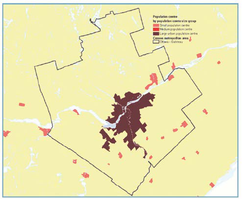
Class 1 identifies the degree of urbanization
around the monitoring site (Figure 6-2). The
Statistics Canada census population centre
(PC) classification (Statistics Canada 2017a,
Dictionary) is used to define levels of
urbanization. A PC is a populated place or a
cluster of interrelated populated places having
a population of at least 1,000 people and a
density of no fewer than 400 people per km
2
,
based on the latest census. All areas outside
PCs are classified as non-urban (rural) areas.
Taken together, PCs and non-urban areas cover
all of Canada.
A 250 m buffer was used to capture sites that
Figure 6-2 Urbanization

12
are adjacent to but not contained within the PC boundaries.
6.2.2 Class 2: Neighbourhood Population
Class 2 summarizes the size of residential populations residing within 4 km of NAPS monitoring
sites (Figure 6-3). A distance of 4 km represents the maximum distance associated with a
neighbourhood scale of spatial representativeness (Section 7.2). Census “block-face” population
(the smallest geographic area for which
census information is collected) was
used to determine the residential
population within 4 km.
Six population size categories have
been selected to maximize the
differences between sites. They are
meant to aid in the grouping of similar
sites and provide insights into emission
source strengths, such as domestic
heating. The neighbourhood population
provides further information to inform
population exposure assessment.
6.2.3 Class 3: Local Land Use
Class 3 represents the dominant land use category within a 400 m radius around each site (Figure
6-4). A radius of 400 m was selected because this distance represents the middle scale of spatial
representativeness (Section 7.2) and corresponds to the US Air Quality System metadata, which
summarizes land use within a quarter-mile radius of sites.
Land use data sets are used to assess this
classification. The DMTI Spatial
©
data set,
at a spatial resolution of 30 m, covers
exclusively urban areas and includes
residential, industrial, commercial,
government and institutional, open, parks,
and waterbody classifications. The
government and institutional classifications
are not included in the NAPS classification,
as this category captures a diverse mix of
land use types.
The forested and agriculture land use
classifications come from the 2010 North
American Landscape Characterization
Figure 6-4 Local land use
Figure 6-3 Neighbourhood Population

13
(NALC) data set, which covers all areas of Canada, at a spatial resolution of 250 m, since these
are not available in the DMTI Spatial
©
data set. The higher spatial resolution (30 m) 2010 land use
data set produced by Agriculture and Agri-Food Canada was also used in conjunction with the
NALC for the current version update in 2017. Similar to NALC, this data set covers the entirety
of Canada and includes the classifications of forest, cropland, settlement, wetland and waterbody.
Aerial imagery is required to classify monitoring sites that meet one of the following criteria:
• have incomplete DMTI Spatial
©
data within the 400 m buffers
• are under DMTI Spatial
©
’s government and institutional classification
• are under DMTI Spatial
©
’s open area category and have a NALC urban classification
• are under DMTI Spatial
©
’s resource and industrial classification.
Eight categories are used to describe the land use surrounding NAPS sites (Table 6-2).
6.2.4 Class 4: Site Type
Class 4 characterizes sites in terms of source influences. These include general population
exposure, regional background and local source–influenced (transportation and point source).
General Population Exposure
General population exposure sites measure urban background conditions where concentration
gradients are usually small, so measurements tend to be quite representative of larger areas and
thus are suitable to assess community-wide or neighbourhood-wide population exposure. This site
type is the most common in the NAPS Program (Figure 6-5).

14
Figure 6-5 Site Types
Regional Background
Regional background sites are sited outside of urban areas to measure:
• air pollutants flowing into an urban area from distant sources, including transboundary
sources
• air pollutants flowing out of an urban area
• background concentrations.
These sites are used to determine the contribution of local sources versus distant sources to air
pollutant concentrations. They may also be sited to extend the spatial coverage of monitoring for
use in air quality forecasting, mapping, modelling and remote sensing applications.
Local Source–Influenced
Local source–influenced sites tend to be pollutant-specific and include both transportation-
influenced and point source–influenced sites. They are sited to represent air pollutant exposure to
populations residing within the influence of the source(s).
Transportation-influenced sites
These sites are located in areas significantly impacted by transportation emissions (defined as
within 100 m of a major roadway). A distance of 100 m was selected based on a review conducted
by the Health Effects Institute (2010) on traffic-related air pollution (TRAP) gradients and health
15
effects. Major roadways are classified as having volumes greater than 15,000 annual average daily
traffic (AADT) counts. Only sites within 100 m of major roadways in large urban or medium urban
areas are classified as transportation-influenced based on a review of the traffic volumes in
urbanization classes.
Other types of transportation-influenced sites (off-road vehicles and engines, rail, marine and
aviation) are classified according to their proximity to these sources and based on an analysis of
the air quality data.
Point source–influenced sites
These sites are located in populated areas close to a major VOC (typically within 10 km) and SO
2
(~1 kt or greater per year) stationary emissions source. An analysis of point source sites indicated
much higher levels of SO
2
or VOC compared with transportation and general population exposure
site types, confirming that the point source sites are being significantly influenced by these sources.
Site classification should be documented in the Networks’ central databases as metadata records
and will help end-users and analysts with data interpretation and reporting.

16
Table 6-2 NAPS site classification system
Site class
Variables
Definition
Code
Urbanization
large urban area
large PC
1
(population ≥100,000)
LU
medium urban area
medium PC
1
(population between 30,000 and 99,999)
MU
small urban area
small PC
1
(population between 1,000 and 29,999)
SU
non-urban (rural) area
non-urban area
1
(population <1,000)
NU
Neighbourhood
population
<500
categories of residential population within 4 km of site
P1
500–9,999 P2
10,000–49,999 P3
50,000–99,999 P4
100,000–149,999 P5
≥150,000 P6
Local land use residential
the dominant land use category within a 400 m radius
R
commercial C
industrial I
parks P
water W
agriculture A
forested F
open O
Site type
general population
exposure
site located in an urban area where populations live,
work, shop, play, and that are not classified as
transportation or point sources
PE
regional backgrounds
site outside urban area RB
transportation
source–influenced
site within 100 m of a major road
2
or influenced by off-
road vehicles and engines, rail, marine or aviation
sources located in an urban area
T
point source–
influenced
site near (< ~10 km) a major stationary emissions
source
3
located in an urban area; classification based
on VOC and SO
2
4
ambient measurement data
PS
1 A population centre (PC) is defined as having a minimum population concentration of 1,000 people and a population density of at
least 400 people per square km. All areas outside PCs are classified as non-urban (rural areas) (Statistics Canada 2017a).
2 All freeways, highways, and arterial and collector roads with an AADT >15,000 (US EPA 2018).
3 Stationary sources include: industrial facilities, power generation, incinerators and waste-treatment plants.
4 SO
2
emissions greater than ~1,000 tonnes per year (RWDI 2016)
17
6.3 Equipment Information and Inventory
Along with station documentation, each Network should maintain an up-to-date inventory of all
monitoring equipment in use. This inventory should include:
• type of equipment used
• ownership information
• purchase price and date of receipt
• equipment description (name and manufacturer)
• equipment identification number (where applicable: e.g., model and serial number)
• equipment location and history (e.g., date of installation).
6.4 Standard Operating Procedures (SOP) for the NAPS Program
SOP are task-specific or method-specific documents that detail the method for an operation,
analysis or action with thoroughly prescribed steps. SOP can help ensure consistent performance
with organizational practices. They can also serve as training aids, provide ready reference and
documentation of proper procedures, reduce error occurrences in data, and improve data
comparability, credibility and defensibility. Networks should reference relevant SOP in their
NQAP and also ensure that applicable SOP and all manufacturer operation and maintenance
manuals are accessible for reference on site.
NAPS Operations has developed a number of technical SOP and forms. NAPS SOP related to
continuous analyzers and monitors, procedures for collecting integrated samples, data collection,
management and reporting processes are referenced in Appendix A.
These SOP contain most of the information needed for a given method or procedure, but users
should modify them to accurately reflect the methods and procedures implemented.
7.0 NETWORK DESIGN AND SITE LOCATION
The NAPS Program was established in 1969 to monitor and assess the quality of ambient air in
the populated regions of Canada. The primary purpose of the Program was to support the
development of Canada-wide air quality objectives for criteria air contaminants and subsequently
to track progress towards achieving these objectives. The scope of the Program has evolved to
include monitoring the precursors and components of air pollutants, identifying the sources and
regions that contribute to air pollutant levels, and providing timely air quality information to the
public. However, characterizing air quality for the achievement of Canada-wide ambient standards
and objectives continues to be the primary focus of the NAPS Program.
18
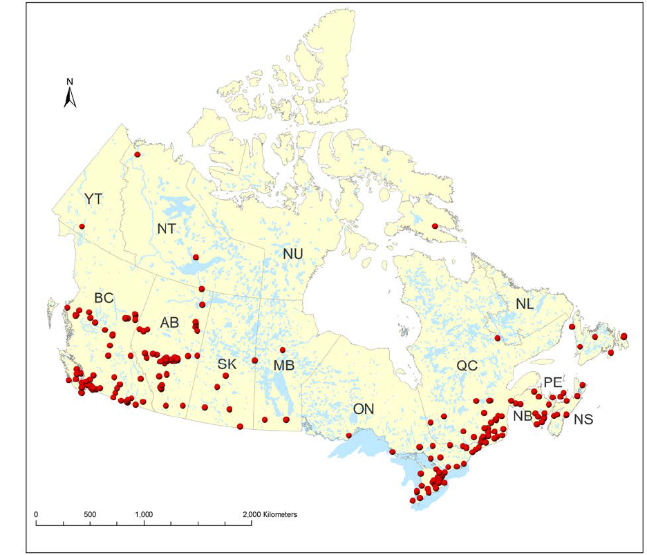
Figure 7-1
NAPS sites
Human health is the key driver for the establishment of the Canadian Ambient Air Quality
Standards (CAAQS). As such, locating NAPS sites (Figure 7-1) in populated areas is the highest
priority. Canada has a small population living in a large land area, leading to a low population
density compared to other countries. The Canadian population, however, is highly concentrated
geographically (Figure 7-2). In 2016, two out of three people (66%) lived within 100 km of the
southern Canada–United States border, an area that represents about 4% of Canada’s territory
(Statistics Canada, 2017b).
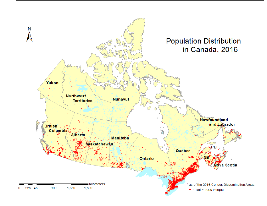
19
Figure 7-2 Population distribution in Canada, 2016
The network design will depend on human health effects as well as the magnitude and distribution
of pollutant concentrations within a defined area or region. Monitoring of air pollutants for which
there is no safe level for health effects (e.g., NO
2
, O
3
, PM
2.5
) should focus on sites located within
densely populated areas.
All census metropolitan areas (CMA) and census agglomerations (CA) with a population greater
than 100,000 should have at least one monitoring site. There are 41 CMA and CA in Canada with
a population greater than 100,000 (2016 Census; see Statistics Canada 2017a). These account for
73% of the total population. However, regionally important urban areas and communities with air
quality concerns should also be considered as a priority for air quality monitoring sites.
Within urban areas, Networks must determine the number of sites to be deployed and their
distribution (for many communities there will only be one site). The typical approach to monitoring
in urban areas involves placing sites at carefully selected representative locations, chosen to meet
the desired monitoring objectives and considering the emission and dispersion patterns of the
pollutants being monitored. The representativeness of a site will depend on the spatial variability
of air pollutant concentrations across a defined area. These variations occur as a result of several
factors, including emission characteristics, atmospheric conditions, topography, urban effects,
chemical transformations, and natural removal processes. Modelling and other assessment
20
techniques may be used to assess how representative a monitoring site is of a community or
neighbourhood.
Sites for monitoring pollutants associated with local sources (e.g., CO, PAH, SO
2
, VOC) should
be optimally sited for measurement data to be useful. Data from these sites may also be used to
identify sources or regions (as tracers for certain emission types) that contribute to poor air quality
and to assess long-term trends in air quality.
Another consideration for network design is the extent of the air pollution coverage. If the air
pollutant is mostly of local origin, then sites will be focused in urban areas. If there is a substantial
regional contribution to the pollutant concentrations, additional sites may be located outside of
urban areas to measure the portion that comes from regional transport or background sources (e.g.,
O
3
, PM
2.5
, VOC).
There has been and continues to be a very large monetary investment in air quality monitoring in
Canada. This investment and the importance of air quality data demand strategic planning and
design to ensure that the network provides adequate coverage to characterize air quality conditions
that address NAPS monitoring objectives. Selecting sites that satisfy multiple objectives will
reduce costs and maximize the efficiency of the network. Wherever feasible, air pollutants that
share similar characteristics (e.g., spatial variability, common sources, health or environmental
impacts) should be monitored at the same site.
Networks should recognize that air monitoring networks are dynamic and should adapt to changes
in air pollution patterns, as well as address new and emerging air quality issues. Each monitoring
network should be evaluated periodically to assess whether its objectives are being met. Networks
may relocate sites to meet changes in requirements, as warranted. However, sites with long trend
record should not be moved unless continued operation is no longer possible. In such a case, every
effort should be made to ensure that the new location measures comparable data. This will allow
for analysis of long-term air quality trends.
7.1 Network Design
The NAPS Network has, as its foundation, a subset of “core” monitoring sites that measure a
comprehensive set of air pollutant parameters. These sites satisfy many monitoring objectives and
provide the basis for multi-pollutant characterizations across a range of site types. The core sites
operate in addition to the other NAPS sites, which are designed specifically to meet various
program and pollutant-specific requirements (Figure 7-3 and Figure 7-4).
7.1.1 Core Sites
Core sites include a comprehensive set of measurements at a select number of representative
locations across Canada that addresses multiple monitoring objectives.

21
The integrated NAPS PM
2.5
reference method
(RM) sampling sites form the basis of the core
sites. In addition, continuous PM
2.5
, O
3
and
NO
2
parameters should be included, as a
minimum. Additional parameters (e.g., CO,
PAH, integrated PM
10-2.5,
SO
2
, VOC) are
measured at a subset of core sites.
Factors that are to be considered for locating
core sites include:
• Population (including regional
population centres)
• geographical and spatial
representativeness
• areas with known or suspected high
pollutant concentrations
• areas influenced by local emission
sources.
It is not feasible or necessary to measure all
pollutants at core sites and as such, two levels
or tiers of core monitoring sites are identified
as Tier 1 (T1) and Tier 2 (T2).
This tiered approach specifies the parameters measured at core sites, and T1 features the most
comprehensive set of parameters (Table 7-1).
Table 7-1 Parameters monitored at core
sites
Parameter T1 T2
PM
2.5
RM
x x
Continuous PM
2.5
x x
O
3
x x
NO
2
x x
PM
2.5
speciation
x
SO
2
x o
CO x o
VOC x o
Integrated PM
2.5-10
x o
Carbonyl o o
PAH o
Meteorology R
x = monitored
o = optional
R = recommended

22
Core stations are located so as to support different site types at various spatial scales.
Tier 2 Sites
The NAPS PM
2.5
reference method (NAPS PM
2.5
RM) forms the basis of the T2 core monitoring
sites. In each province or territory, the recommended number of sites increase with population
(in million) as follows:
Population
Number of sites
<1 million at least one
≥1 million to <2 million at least two
≥2 million to <4 million at least three
≥4 million to <6 million at least four
≥6 million to <8 million at least five
≥8 million to <10 million at least six
≥10 million to <12 million at least seven
≥12 million at least eight
In Canada, the NAPS PM
2.5
RM uses a time-integrated filter-based method for determining PM
2.5
mass. Although the US EPA’s testing procedures for PM
2.5
automated federal equivalent methods
(FEM) approval (US EPA 2006) covers a diverse range of conditions, side-by-side comparisons
Figure 7-3 Graphical concept of core sites
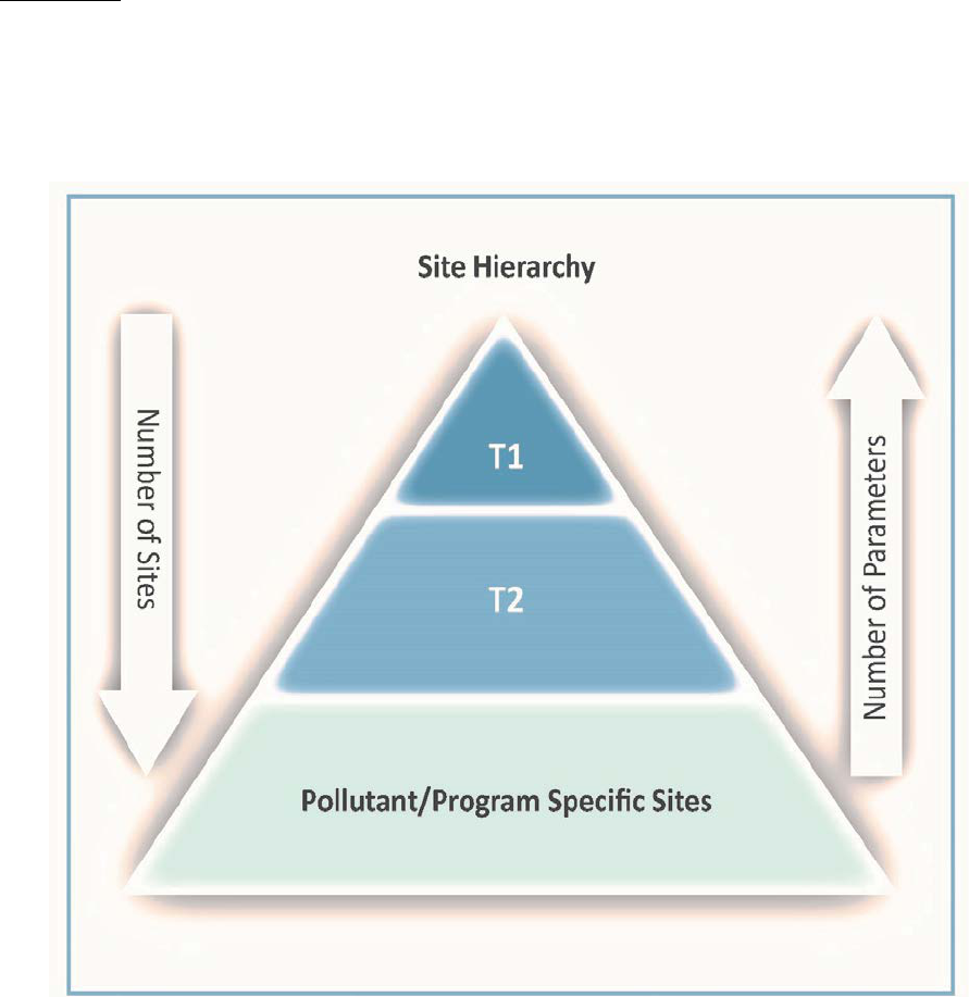
23
of different FEMs and the NAPS RM has shown that instruments do not always agree with one
another over varying timescales and meteorological conditions. It is recommended that each
Network operate at least one co-located NAPS PM
2.5
RM with the FEM instrument models
deployed in their network. Larger Networks should deploy additional co-located NAPS PM
2.5
RM
sites to compare with their FEMs (Table 7-2).
Tier 1 Sites
T1 core sites are based on the PM
2.5
speciation sampling sites. T1 sites can also serve as platforms
to support the introduction of monitoring technologies to the NAPS Program by testing and
evaluating new instruments and parameters (e.g., ultra-fine particles and continuous black carbon).
Figure 7-4 NAPS site hierarchy
7.1.2 Program-specific Sites
Most sites in the NAPS Program support the following policy initiatives:

24
Air Quality Management System and Canadian Ambient Air Quality Standards
CAAQS have been developed for PM
2.5
, O
3
, NO
2
and SO
2
. They are established as objectives
under the Canadian Environmental Protection Act 1999 (CEPA).
The following site distribution is recommended for reporting on achievement of CAAQS:
• In communities with a population greater than 100,000, at least one site measuring
continuous PM
2.5
, O
3
and NO
2.
• In each provincial or territorial air zone (Figure 7-5), at least one site measuring
continuous PM
2.5
, O
3
and NO
2.
• The highest priority for measuring SO
2
should be in communities where populations are
(or may be) exposed to levels within the health effects range (>40 ppb, one-hour
average). Other priorities include core sites (T1 and possibly T2) and trend sites (CESI)
• Based on considerations such as regional population density, proximity to point sources,
local air quality and public concern, sites measuring NO
2
, O
3
, continuous PM
2.5
or SO
2
could also be located in communities with populations of less than 100,000.
• Regionally representative background sites measuring, as a minimum, PM
2.5
and O
3
.
Figure 7-5 AQMS air zones

25
Air Quality Health Index (AQHI)
The Air Quality Health Index (AQHI) is delivered in partnership with Health Canada and the
provincial and territorial governments. This index provides a current hourly value and a two-day
air quality forecast for communities across Canada. Warnings and alerts are also issued when
conditions warrant. In addition, the AQHI includes messaging on how to reduce personal health
risks and air pollutant emissions from individual activities.
To deliver the AQHI to Canadians, consistent and reliable data are required from at least one site
measuring continuous PM
2.5
, O
3
and NO
2
for a community or a determined forecast region.
7.1.3 Pollutant-specific Sites
Other than the previously mentioned program-specific and core sites, the NAPS Program supports
additional sites that are mainly targeted to specific secondary monitoring objectives
(Section 2.0).
VOC Sites
The NAPS Program includes measurements of VOC. In addition to being an important precursor
to the formation of ground-level O
3
and PM (secondary organic aerosol), individual VOC species
have been declared “toxic” under CEPA.
A program of systematic year-round measurements of VOC began in 1989 at a large number of
urban sites across the country. Several non-urban sites were added to the Program in 1993.
Measurements of VOC are important in both characterizing emission changes in O
3
precursors
and in characterizing human health effects from toxic species. Consistent methodology applied in
the NAPS Program provides accurate trend determinations. Speciated VOC measurements can
also be used to infer emission contributions and validate emission inventories.
Near-road Sites
Living near major roadways has been identified as a risk factor for various health outcomes.
Statistics Canada estimates that 4 million Canadians, about 13% of the total population, live within
100 m of a major road (Evans et al. 2011). Information from these sites is used to characterize air
quality near roadways and the spatial extent to which Canadians are exposed to TRAP.
The recommended criteria for near-road sites should include:
• at least one site for CMA with a population greater than 1 million
• the following parameters: black carbon, CO, NO
2
, O
3
, PM
2.5
, SO
2
, ultra-fine particles
and traffic counting
• if resources allow, a second near-road site for CMA with a population greater than 2.5
million
• locating the stations within 30 m of the outside edge of the nearest traffic lane.

26
Note: A major roadway with an AADT greater than 30,000 is recommended for near-road sites.
AADT is defined as “the total volume of vehicle traffic of a road for a year, divided by 365 days”
(U.S. Department of Transportation, Federal Highway Administration 2014).
Regional background sites
Regional background sites are located outside of urban areas to measure:
• air pollutants flowing into an urban area from distant sources, including transboundary
sources
• air pollutants flowing out of an urban area
• background concentrations.
These sites are used to determine the contribution of local sources versus distant sources to air
pollutant concentrations. They may also be sited to extend the spatial coverage of monitoring for
use in air quality forecasting, mapping, modelling and remote sensing applications.
7.2 Site Location Selection Process
Multiple steps are required for designing and implementing a monitoring network and selecting
site locations (Figure 7-6):
• identify the program or purpose for monitoring (e.g., CAAQS)
• determine the monitoring objective(s)
• siting stations
• identify the number and location of sites (e.g., communities with a population > 100,000)
• select the pollutants to be monitored by determining:
o the site type
o the most appropriate spatial scale (Table 7-2 and Figure 7-7)
• investigate information on land use, including transportation and point sources that may
impact air quality
• identify possible locations that would meet monitoring objectives and the populations
living in the surrounding area.
A number of practical considerations should be accounted for prior to final site selection:
• sampling inlet spacing criteria (Section 8.0)
• station design within existing structures (e.g., inlet or exhaust holes, access to roof)
• site suitability in terms of terrain
• security against unauthorized access and vandalism
• site safety
• availability of power
• soil conditions
• underground utilities
• availability of communication systems (e.g., cellular reception, land line or satellite)
• year-round accessibility
• property ownership
• long-term viability of the site

27
• acquiring a lease or agreement from the property owner to install a monitoring station
• obtaining permit(s) to install and operate the monitoring station.
Note: Ideal siting may not be possible for practical, logistical or other reasons. Networks may
consult with NAPS Operations in cases where proposed new locations do not meet all
recommended criteria.
Figure 7-6 Design requirements of the monitoring network and the selection of
sites
7.2.1 Prioritizing Monitoring Objectives
Section 2.1 identifies the monitoring objectives for the NAPS Program. However, these objectives
do not apply to all the pollutants monitored under NAPS, nor do they indicate their relative
importance. Table 7-2 provides a qualitative priority ranking (low, medium, high) of these
objectives for each of the pollutants monitored. This ranking is based on factors such as data usage,
pollutant levels, air quality programs or policies, and network reviews. The relative priority of a
particular monitoring objective may vary according to the data user.
7.2.2 Spatial Scales of Representativeness
Representativeness is one of the DQO for the NAPS Program. The spatial representativeness of a
particular monitoring site is dependent on a number of factors, such as topography, meteorological
conditions, proximity to sources, and the chemical and physical properties of the pollutant being
measured. The goal when siting stations is to correctly match the spatial scale represented by the
air sample with the scale most appropriate for the monitoring objective at the site. To satisfy the

28
Program’s primary monitoring objectives, NAPS sites are generally spatially categorized as
neighbourhood or urban scales. Table 7-3 and Table 7-4 show the relationship between spatial
scale of representativeness and the pollutants measured and site types respectively.
Figure 7-7
Spatial scales
This document defines five categories of spatial scales of representativeness, these are:
• MI (micro) = concentrations in air typical of areas ranging from several metres up to
approximately 100 m
• M (middle) = concentrations in air typical of areas up to several city blocks ranging from about
100 m to 0.5 km
• N (neighbourhood) = concentrations in air typical of some extended area of the city that has
relatively uniform land use on the order of 0.5–4 km
• U (urban) = concentrations in air typical of the overall city-wide area on the order of 4–50 km
• R (regional) = usually a non-urban area of reasonably homogeneous geography that may extend
from tens to hundreds of kilometres (U.S. EPA 1997).

29
Table 7-2 Monitoring objective priorities by pollutant and spatial scales of
representativeness
Monitoring objectives
CO
NO
2
O
3
SO
2
PM
2.5
Cont.
PM
2.5
Int.
PM
2.5–10
Int.
PAH
VOC
Appropriate
spatial
scales
Track and report progress
on achievement of air
quality objectives or
standards
low high high high high N,U
Measure representative
pollutant concentrations
in populated areas and
enable the determination
of long-term trends in air
pollutant concentrations
low
med
med
low
med
low
low
low
med
M,N,U
Provide air pollution
information to the public
high high med high M,N,U
Support development of
air management
strategies
low low med low med low low med M,N,U
Support research studies
to assess air pollution
impacts on health and
ecosystems
low low low low med low med med M,N,U
Verify and validate
emissions inventories,
models, mapping, and
support forecast and
advisory programs
med med low med low low U,R
Measure highest
representative pollutant
concentrations in
populated areas
med med med med med low MI,M,N
Measure regional
background
concentrations and
transport of pollutants
from regional sources
(including transboundary)
low
med
low
med
low
low
low
U,R
Measure air pollution
upwind and downwind of
urban areas
low low low low low U,R
Support regional,
Canada-wide and
international air quality
agreements and
initiatives
low low low low low med low U,R
Support development and
evaluation of new
monitoring technologies
low low med med low MI,M,N
Cont. = continuous
Int. = integrated

30
Table 7-3 Pollutants and relevant spatial scale of representativeness
CO NO
2
O
3
SO
2
PM
2.5
Cont.
PM
2.5
Int.
PM
2.5–10
Int.
PAH VOC
Micro * * * * * *
Middle * * * * * * *
Neighbourhood * * * * * * * *
Urban * * * * *
Regional * * * * *
7.2.3 Site Types
There are three monitoring site types (Section 6.0):
• general population exposure
• regional background
• local-source influenced (transportation and point source).
Table 7-4 Site types and spatial scale of representativeness
Micro Middle Neighbourhood Urban Regional
General population exposure * *
Regional background *
Local source–influenced:
transportation
* *
Local source–influenced: point
source
* *
General Population Exposure Sites
Population or community-oriented monitoring sites are used to determine the area-wide exposure
to air pollutants. These sites should be located within the urban boundary (urbanization
classification) in residential, commercial or other areas where people spend significant amounts of
time, and the levels measured should not be unduly influenced by individual sources. Local land
use and neighbourhood population classifications can be useful in determining optimal site
locations.
Existing sites should be assessed periodically to ensure that they measure representative
concentrations in densely populated areas (i.e., >P1), in contrast to sites located in less populated
areas that may not necessarily represent the entire area under consideration.

31
Regional Background Sites
Regional background sites are located in non-urban (rural) areas upwind or downwind of
communities to measure air pollution from regional sources or background levels.
These sites should be located in sparsely populated areas (i.e., P1 or P2) away from significant air
pollution sources (i.e., >250 m from major roadways and >15,000 AADT; > ~10 km from point
sources emitting > ~1 kt/year). It is also desirable to site these stations in an open area, away from
tree canopies and preferably on high ground.
Regional background sites may also be deployed to extend the geographical coverage required for
air quality forecasting, mapping, modelling and remote sensing.
Local Source-Influenced Sites
Transportation-influenced sites
Sites located in populated areas influenced by traffic located within 100 m of a major road (defined
as all freeways, highways, and arterial and collector roads), or by other forms of transportation
such as off-road vehicles and engines, rail, marine or aviation sources.
Traffic-influenced sites are located in large urban (LU) and medium urban (MU) PCs near major
roadways (AADT >15,000).
Point source-influenced sites
Sites located in populated areas close (typically within 10 km) to a major stationary emissions
source. These sites are primarily located near large VOC or SO
2
(~1 kt/year or greater) sources,
which are the pollutants most influenced by stationary source emissions.
Note: Fence-line monitoring sites are not reported to the NAPS CWAQD. They are defined as
“sites that are located within or on the property line of a facility or those sites that are very near to
a facility and in areas not used or accessed by the public or with no nearby population of
appreciable size” (RWDI 2016).
7.2.4 Population Density
An important consideration in the selection of a NAPS monitoring site is the population living
nearby. For urban monitoring, sites should be located in densely populated areas. Conversely, sites
that are intended to capture regional background concentrations should be located in sparsely
populated areas. There are six categories of neighbourhood population (Table 6-2).
32
7.2.5 Local Land Use
The dominant land use assigned within a 400 m radius of each site, which corresponds to the
middle scale of representativeness, must conform to the monitoring objectives and site type
(Section 6.2.1). General population exposure and local source–influenced sites should be located
in residential, commercial or industrial land use categories. Regional background sites are located
in agricultural, forested, water or open land use categories. Park category sites may be located in
either urban or non-urban areas.
8.0 MONITORING STATION DESIGN
8.1 Station Design
The proper design of a monitoring station is crucial and takes into consideration air sample
integrity, instrument requirements, functionality and operator safety. Requirements and
considerations for station design include the following:
• Stations must be secure, with restricted access to the public.
• All electrical circuits should adhere to provincial and territorial electrical codes.
Electrical circuits located outdoors should use ground-fault circuit interrupters and be
able to support load demands.
• The station and monitoring system must adhere to provincial and territorial safety codes,
be equipped with an ABC-class fire extinguisher and a first aid kit and have a mobile
telephone or land line available.
• The station should be designed with sufficient lighting, access to instrumentation and a
workspace for the station operator.
• The station should be designed with reliable power and communications systems. For
sites with transient power, a line and power conditioning system should be added.
• The shelter must be ventilated, heated and cooled to maintain a stable temperature in the
desirable range of 20-30°C throughout the year.
• Instrument racks inside a station should be properly secured, and instruments should be
installed to allow air to circulate freely to avoid overheating.
• The station should be designed to ensure safe access to the roof, including appropriate
guardrails (as required by local safety codes) to prevent falls.
• Gas cylinders should be properly mounted.
8.2 Sampling Inlet System Design
Components of a sampling inlet system vary by method and can include a PM-sized selective inlet,
an inlet line or probe, a manifold (and bypass pump), filters, and sample lines to the instruments.
The sampling inlet system should be designed to prevent water from entering the air stream (using
a rain cover such as a funnel) and should follow the manufacturer’s installation requirements,
NAPS methods, SOP and guidelines.
One important consideration for the sampling inlet system is that all components in contact (or

33
close contact) with the air sample prior to analysis (including the tubing and manifold) must be
non-reactive (Table 8-1) with the pollutants measured. Also, to reduce residence time (Rt) within
the system, all sample lines should be kept as short as possible.
Table 8-1 lists acceptable sampling inlet system material and required sample Rt. Section 8.3.1
provides Rt definition and calculations.
Table 8-1 Sampling inlet material and Residence Time (Rt)
Pollutant
Inlet system components
Lines to manifold
Sample Rt
CO
borosilicate glass (e.g., Pyrex), quartz or Teflon
clear Teflon ¼ -inch
(FEP, PFA, PTFE)
<20 seconds
4
NO
X
O
3
SO
2
PM
borosilicate glass (e.g., Pyrex), quartz or conductive
material, such as stainless steel or anodized
aluminum
1,2
N/A
PAH
conductive material, such as stainless steel or
anodized
aluminum
1,2
N/A
VOC
borosilicate glass (e.g., Pyrex), quartz or stainless
steel
2
clear Teflon ¼ -inch
3
1 For PM instruments, anodized aluminum inlet system components are often provided by the manufacturer.
2 Teflon or other plastics are not acceptable materials for PM and PAH monitoring, because these materials can become statically
charged and attract particles.
3 Sampler lines to the Summa canister must be stainless steel or nickel.
4 Although <20 seconds is required, ~10 seconds is preferable to allow for variability in flow rates.
A manifold system with a water trap to collect condensation is preferable for a monitoring station
with multiple gas analyzers, rather than separate sample lines for individual instruments.
For continuous and integrated PM monitoring, manifold systems are not recommended. These
instruments should use individual inlets, and the sampling tube from inlet to instrument should be
as vertical as possible to avoid particle loss due to impaction.
8.2.1 Sampling Inlet Placement
The sampling inlet is an opening through which an air sample enters the sampling inlet system
before being routed to an analyzer, monitor or sampler. These inlets are either provided by the
instrument manufacturer or custom designed.
To obtain a representative air sample, placement of the sampling inlet should meet the following
recommended spacing criteria for height, obstructions, roadways and distance between inlets.

34
Specifications for spacing of sampling inlets relative to roadways at neighbourhood and urban
scales are listed in Table 8-2, and spacing requirements relative to obstructions that can alter air
flow are listed in Table 8-3.
Table 8-2
Minimum separation distance between roadways and sampling inlets
1
for
neighbourhood and urban scale sites
Annual average daily traffic (vehicles per day) ≤10,000 ≤15,000 ≤20,000 ≤40,000 ≤70,000 ≥110,000
Minimum distance between roadway and inlet
(metres)
2
≥10 20 30 50 100 ≥250
1 For traffic-influenced sites (where AADT value exceeds 15,000), the inlet must be located within 100 m (maximum) of the
roadway.
2 Distance to the nearest traffic lane. The distance for intermediate traffic counts should be interpolated.
Table 8-3 Specifications for sampling inlet siting
Pollutant
Height from ground to
inlet (metres)
1
Horizontal and vertical
distance from supporting
structures to inlet
2
(metres)
Distance from inlet to any air
flow obstacle
3
(e.g., bui
ldings,
trees) (metres)
CO 2–15 >1
>2 × height of obstacle above
inlet
2
NO
X
2–15 >1
O
3
2–15 >1
SO
2
2–15 >1
PM 2–15 >2
PAH 2–15 >2
VOC 2–15 >1
1 For micro up to neighbourhood scales, the maximum height should be as low as feasible.
2 When inlet is located on a rooftop, this separation distance is in reference to roof, walls, parapets or other structures located on
the roof.
3 Must have unobstructed air flow 270° surrounding the inlet (180° if located on the side of a building).
For flow rates less than 20 litres per minute (L/min), sampling inlets must be at least 1 m apart and
at least 2 m apart for flow rates greater than 20 L/min (distance measured from centre of inlets).
Sampling inlets for co-located instruments should be no greater than 4 m from each other.
In addition to the requirements listed in the tables above, sampling inlet placement should consider
the following:
• If an inlet is located on the side of a building, ideally it should be located on the side of
prevailing winds.
• Inlets should not be placed in close proximity to air outlets (e.g., exhaust fans).
• To avoid undue local influences, inlets should be located away from minor sources such
as fugitive emissions, exhausts or stacks.
• Inlets should be located away from dirty or dusty areas (such as dirt roads).
• Areas subject to possible heavy snow accumulation should be avoided.
35
8.3 Manifold Design
For a monitoring station with multiple gas analyzers, an air sampling manifold can reduce excess
moisture, pressure drops and dust entrainment.
Manifold designs commonly used for NAPS monitoring include either a conventional borosilicate
glass (Pyrex) or quartz manifold with a blower motor (Figure 8-1), or an octopus-style manifold
system (Figure 8-2).
Important considerations and requirements for manifold design include the following:
• Check that air flow is unrestricted, with minimal bends.
• Install a water trap at the manifold.
• For gas analyzers, install Teflon filters between the manifold and the analyzer’s sample
inlet port, unless the analyzer is configured with an existing internal filter. Note that
filters located before the manifold inlet are not recommended, as the flow restriction
created by a filter may limit the ability of a fan or blower to provide a sufficient flow
rate. More importantly, the filter will create a vacuum in the manifold.
• Ensure air flow through the manifold does not cause the pressure inside the manifold to
be more than 1 inch of water below the ambient pressure. The methodology for
determining pressure drops is described in Section 8.3.2.
• Use individual sampling lines and inlets for VOC or carbonyl instruments. However,
they may be connected to a manifold only if a conventional 4-inch, 2-inch or 1-inch
manifold is used.
• Take care to ensure that the inlet system does not have any leaks. Calibration checks
through the entire sampling inlet system will indicate possible dilution due to leaks.
• Check that placement of the calibration gas lines be designed to challenge the entire
measurement system, including the sampling line and manifold system.
• Vent exhaust from analyzers and the manifold outside and away from the sample inlet
using an exhaust manifold or individual lines. If using individual lines, ensure that they
are of minimal length to avoid back-pressure to the analyzer. If venting to the outside is
not possible, the exhaust should be scrubbed before venting into the station.

36
Figure 8-1 Example of a conventional 1-, 2- and 4-inch manifold system (which can
be configured horizontally or vertically)
Figure 8-2 Example of octopus-style manifold system
37
8.3.1 Residence Time (Rt) Calculations
Rt is defined as the amount of time that it takes for a sample of air to travel from the sampling inlet
to the instrument. Although a 20-second Rt is the maximum allowed, it is recommended that the
Rt within the sampling inlet system be approximately 10 seconds to allow for variability in flow
rates.
The Rt is determined as follows. First, calculate the total volume using the following equation:
Total volume = C
V
+M
V
+ L
V
Where:
C
V
= volume of the sample probe and extensions
M
V
= volume of the sample manifold and trap
L
V
= volume of the sampling line to the instrument
Once the total volume is calculated, divide the sum of the flow rates of all instruments to obtain
the Rt. If the Rt is greater than 20 seconds, attach a blower or metered pump to increase the flow
rate and decrease the Rt to the acceptable level.
8.3.2 Pressure Drop Measurements
If a manifold system is used, the air flow through the sample system must not create a pressure
drop greater than approximately 1 inch of water below the ambient pressure. The pressure drop
should be assessed as follows:
• measure the ambient pressure near the manifold
• measure the pressure inside the manifold by attaching a manometer to a spare sampling
port on the manifold
• calculate the pressure drop
• adjust the flow rate to ensure that the pressure drop is less than 1 inch and the Rt
requirements are met.
If these requirements cannot be met, the manifold volume is too small, and an appropriately sized
manifold must be used.
9.0
MONITORING, SAMPLING
AND ANALYTICAL METHODS
To achieve the NAPS DQO for accuracy and comparability, monitoring, sampling and analytical
methods must meet defined minimum performance specifications for the following pollutants:
Continuous (hourly) parameters:
• CO
• NO, NO
2
, NO
X
• O
3
• SO
2
• PM
2.5
38
Integrated sampling:
• PM
2.5
and PM
2.5–10
o mass concentration
• PM
2.5
components
o major elements
o trace elements
o ions
o inorganic PM precursors: ammonia, nitric acid, SO
2
o organic carbon/elemental carbon (OC/EC)
o levoglucosan and other biomass burning markers
• PM
2.5–10
components
o major elements and ions
• VOC
o non-polar hydrocarbons
o non-polar halogenated
o polar, including carbonyls (e.g., ketones, aldehydes)
• PAH
9.1 Continuous Methods
Analyzers that satisfy the requirements of the US EPA as federal reference methods (FRM) or
FEM for ambient air monitoring are selected for use in the network (US EPA 2018).
Modifications to reference or equivalent methods may be permitted for use within the NAPS
Program if it can be demonstrated that they meet the NAPS performance specifications. The
operating characteristics of these modified instruments will be documented, and their performance
will be evaluated in the laboratory and field for environmental conditions encountered across the
country.
For example, the PM
2.5
FEM requires a very sharp cut cyclone (VSCC), but the use of a sharp cut
cyclone (SCC) is allowed under NAPS because field testing has demonstrated that the SCC
performs as well as the VSCC.
A current list of US EPA reference and equivalent methods is maintained online (US EPA 2018)
and includes approved methods for O
3
, NO
2
, CO, SO
2
and PM
2.5
. Acceptance of the US EPA
FRM and FEM for use in the NAPS Program assures the comparable performance of air quality
measurements.
Non-FRMs/FEMs could be used for the initial assessment of an area prior to selecting an air
monitoring site location.
Table 9-1 lists NAPS minimum acceptable performance specifications for continuous methods.
Table 9-2 lists principles of operation for methods currently used by the NAPS Program for
continuous ambient air monitoring.

39
Table 9-1 NAPS minimum performance specifications and operating ranges
for continuous methods
Pollutant
Instrument
range
1
Operating
range
2
Lower
detection
limit
3
Zero noise
4
Zero drift
(24 hours)
5
Span drift
(24 hours)
6
Rise/fall
time
7
(max.)
CO 0–10 ppm
0–5 or
0–10 ppm
0.04 ppm
0.02 ppm
RMS
<0.1 ppm
<1% of full
scale
60 sec
NO/NO
2
/NO
X
0–500 ppb 0–500 ppb 0.4 ppb 0.2 ppb RMS <0.5 ppb
<1% of full
scale
80 sec
O
3
0–500 ppb 0–500 ppb 1 ppb 0.3 ppb RMS <1 ppb
<1% of full
scale
20 sec
SO
2
0–500 ppb
0–200 or
0–500 ppb
0.1 ppb
<0.06 ppb
RMS
<0.2 ppb
<0.5 % of full
scale
140 sec
PM
2.5
8
0–200 µg/m
3
0–200 µg/m
3
to
0–1000 µg/m
3
2 µg/m
3
(daily)
N/A N/A N/A N/A
ppm = parts per million; ppb = parts per billion; µg/m3 = microgram per cubic metre; RMS = root mean square
1
Instrument range represents the minimum full-scale output that must be available from an analyzer/monitor to be used.
2 Based on the US EPA–approved specified range for the instrument.
3 Lower detection limit refers to the lowest detectable quantity of pollutant that can be distinguished from the absence of the pollutant
(i.e., zero air for gas analyzers).
4 Zero noise is a measure of the deviations from zero while sampling constant zero air. The noise is measured as the RMS of the
deviations from zero.
5 Zero drift (24-hour) is the absolute change in analyzer response to a constant zero air input over 24 hours of unadjusted continuous
operation.
6 Span drift (24-hour) is the percent change in analyzer response to a constant upscale pollutant concentration over 24 hours of
unadjusted continuous operation.
7 Rise/fall time is the time interval between initial response (the first observable change in analyzer output) and a level of signal
output that is 95% of the steady state output after a step increase (rise) or decrease (fall) in input concentration.
8 Range of 0–200 µg/m
3
applicable only if using analog output, 0–1,000 µg/m
3
if using digital output (but not exceeding 2,000 µg/m
3
).
Relying solely on the performance specifications provided by a manufacturer does not necessarily
guarantee that a method will perform as expected in the field during routine operations. To ensure
that NAPS minimum performance specifications are met, appropriate maintenance, operating
conditions and performance evaluations should be followed (as detailed in this Guidance).
The US EPA has approved a number of continuous methods as FRMs or FEMs, including those
found in Table 9-2.

40
Table 9-2 Principles of operation for NAPS continuous methods
Parameter
Principle of operation
CO
Non-dispersive infrared (FRM): This is the most commonly used continuous CO
measurement method. These analyzers operate on the principle that the CO molecule has a
sufficiently characteristic infrared (IR) absorption spectrum for detection. Sample air passes
through a chamber in front of an IR source. Optical bandpass filters focus the wavelength of
the IR energy to the CO absorption range. The detector produces a signal proportional to
the amount of IR absorbed, enabling the concentration of CO to be calculated.
NO/NO
2
/
NO
X
Chemiluminescence (FEM): NO concentrations are determined photometrically by
measuring the light intensity from the chemiluminescent reaction of NO mixed with excess
O
3
. The chemiluminescence method detects only NO, so NO
2
must first be converted to
NO for measurement purposes. Sample flow either is directed through a converter to reduce
NO
2
to NO, or it bypasses the converter to allow detection of only NO. The sample stream
with reduced NO
2
is a measurement of NO plus NO
2
, expressed as NO
X
. The difference
between NO
X
and NO detection is calculated as the NO
2
concentration.
Cavity attenuated phase shift (CAPS) (NO
2
only; FEM): Direct measurements of NO
2
using
CAPS technology are approved as an EPA-equivalent method and are acceptable for
NAPS. CAPS instruments use low-power LEDs, where NO
2
light absorption is directly
correlated to NO
2.
concentration. CAPS analyzers measure only NO
2
, not NO or NO
X
.
O
3
Ultraviolet (UV) photometry (FEM): This is the most commonly used continuous O
3
measurement method. An air sample passes through a beam of light from a UV lamp, which
is absorbed by O
3
. The amount of UV light absorbed is proportional to the amount of O
3
in
the sample. These instruments are favoured due to ease of operation and low maintenance
and because they do not require reagent gases or solutions.
SO
2
UV fluorescence (FEM): This is the most commonly used continuous SO
2
measurement
method. This method is based on the principle that SO
2
molecules absorb UV light at one
wavelength and emit UV light at a different wavelength. The intensity of the emitted light is
proportional to the number of SO
2
molecules in the sample gas. These instruments are
favoured because of their inherent linearity, sensitivity and the absence of consumable
reagent gases.
PM
2.5
Beta attenuation (FEM): Particle sizes (e.g., ≤2.5 µm) are aerodynamically separated before
analysis. For these measurements, filter tape is exposed to ambient sample flow, and PM is
deposited on the filter. Beta rays are emitted from a source and attenuated when they pass
through the deposits on the filter. The beta attenuation through the deposit is blank
corrected using beta attenuation through a clean filter. The blank-corrected attenuation
readings are converted to mass concentrations.
Light scattering (FEM): This method relates light-scattering measurements to mass
measurements, where particle light scattering is determined by illuminating particles and
measuring the scattered intensity at different orientations from the incident light. The
scattering measurement is often highly correlated with mass concentrations, but the
relationship can depend on particle properties like size, shape and composition.
Tapered element oscillating microbalance (TEOM): Particle sizes are aerodynamically
separated before analysis. A TEOM consists of a hollow glass element that oscillates at a
known frequency. The air sample passes through a filter attached to the tapered element.
As particles are deposited on the filter, the oscillating frequency changes in proportion to the
amount of mass deposited. This change in frequency is used to determine PM
concentration. For US EPA equivalency, TEOMs measuring PM
2.5
must be operated with a
Filter Dynamics Measurement System, which corrects for volatilization and other filter mass
loading issues.

41
9.2 Integrated Methods
For the NAPS Program, ECCC conducts chemical and gravimetric analysis of samples at its
ISO17025-accredited laboratories in Ottawa. ECCC also provides sampling media for integrated
samplers, including filters, VOC canisters, cartridge assemblies and filter packs. Accredited
procedures to ensure sample integrity are followed throughout the process from sample preparation
to shipping, collection and analysis.
NAPS PM
2.5
Reference Method (RM)
Atmospheric particulate matter (PM) is a complex mixture of solid and liquid particles including
the vapour-phase semi-volatile compounds that are adsorbed or absorbed to the particle. True
measurement of the aerosol is rarely, if ever done, and therefore, PM
2.5
can only be defined
operationally according to the sampling and mass determination method utilized.
An integrated, 24-hour interval, gravimetric method has been adopted as the NAPS Reference
Method (RM) for PM
2.5
mass concentration measurements. Although constituent mass loss or gain
artifacts can occur during filter sampling, reference methods provide a benchmark for comparing
measurement techniques.
The NAPS PM
2.5
RM collects fine particulate matter of aerodynamic diameter 2.5 μm and smaller
(PM
2.5
) on a pre-weighed Teflon filter using a particle size selective inlet, located on the inlet tube,
by drawing a known volume of ambient air over a 24-hour interval. Once the sampling period is
completed, the filter is removed and transported to the NAPS Laboratory where it undergoes
conditioning and gravimetric weight determination. The average PM
2.5
concentration (in units of
µg/m
3
) is calculated from the mass difference of the filter divided by the actual volume calculated
from the flow meter and the sampling time interval (24 hours).
Brief descriptions of sampling and analysis methods are listed in Table 9-3.

42
Table 9-3 Principles of sampling and analysis for NAPS integrated methods
Parameter Principle of operation
PM
2.5
mass
concentration
(NAPS PM
2.5
RM)
Samples are collected on Teflon filters using the NAPS PM
2.5
RM.
Mass concentrations are calculated from the difference between pre- and post-
sampling weights using sampled volumes. Gravimetric analysis is performed under
controlled environmental conditions.
PM
2.5–10
mass
concentration
Samples are collected on pre-weighed Teflon filters. Mass concentrations are
calculated from the difference between pre- and post-sampling weights using
sampled volumes. Gravimetric analysis is performed under controlled
environmental conditions.
Chemical
Characterization of
PM
2.5
To characterize PM
2.5
and PM
2.5–10
species, samples undergo laboratory analysis
using a variety of techniques such as ion chromatography (precursor gases, ions),
energy-dispersive x-ray fluorescence (ED-XRF) for elements, and inductively
coupled plasma mass spectrometry (ICP-MS) for both near-total and water soluble
metals.
Chemical
characterization of
PM
2.5-10
PM
2.5–10
samples are analysed for elements by energy-dispersive x-ray
fluorescence (ED-XRF), and for PM precursor gases and ions by ion
chromatography.
PM
2.5
Speciation
Samples are collected using a combination of denuders and Teflon, nylon and
quartz filters at PM
2.5
Speciation sites.
In addition to the chemical characterization described above, samples undergo
laboratory analysis using a variety of techniques such as ion chromatography
(precursor gases, ions, biomass burning markers), total optical reflectance for
carbon (OC/EC), energy-dispersive x-ray fluorescence (ED-XRF) for elements, and
inductively coupled plasma mass spectrometry (ICP-MS) for both near-total and
water soluble metals.
VOC VOC are collected using stainless steel Summa canisters. Ambient air is drawn into
an evacuated canister at a constant flow rate.
A combined gas chromatography/flame ionization detector system is used for
quantification of C2 hydrocarbons, while a combined gas chromatography/mass
selective detector system is used for quantification of C3 to C12 hydrocarbons and
chlorinated hydrocarbons.
Carbonyls Samples are collected by drawing ambient air at a constant flow rate through a 2,4-
dinitrophenylhydrazine (DNPH)–coated silica-gel cartridge.
Samples undergo analysis using high-pressure liquid chromatography.
PAH Samples are collected using a NAPS-modified high-volume particulate sampler.
Ambient air is drawn at a constant flow rate through a Teflon-coated borosilicate
glass filter to capture the particle components, in combination with a cartridge that
contains polyurethane foams to trap the gaseous PAH.
Samples undergo analysis using gas chromatography/mass spectrometry.
43
9.3 New Instrument Pre-deployment Testing and Inspection
Testing and inspecting instruments in a controlled environment such as a laboratory or workshop
prior to deployment in the field ensures that they are performing within a manufacturer’s
specifications. This baseline testing may also help identify problems associated with instrument
siting.
9.3.1 Continuous Gas Analyzers
To identify potential issues, several multi-point verifications and zero/span checks should be
performed for at least one week. This testing should also include monitoring of instrument
diagnostics to ensure that the various internal electromechanical, temperature and pneumatic
sensors are performing as expected. Manufacturer operation manuals may include such testing
procedures.
9.3.2 PM Instruments
The most important operating parameter of PM instruments is the flow rate. A calibration should
be performed and all sensors verified (pressure, temperature, flow, etc.). Testing should include
monitoring of instrument diagnostics. To determine instrument stability, the instrument should be
operated with a zero filter (high efficiency particulate air [HEPA]) for at least three days.
Manufacturers’ operation manuals may include such testing procedures.
10.0 ROUTINE OPERATION
Routine operation and maintenance at monitoring sites is the responsibility of the Network, and
includes site- and equipment-preventative maintenance, repairs, instrument checks and
calibrations, as well as sample collection for laboratory analysis. Although routine site visits are
discussed in this section, additional guidelines and schedules for verification and calibration
activities are also discussed in Section 11.0.
10.1 Routine Inspection and Maintenance Checks
Routine visits are necessary to verify the continued operation of the unattended monitoring station
and equipment. Preventive maintenance increases data capture, ensures system reliability, and
helps to identify any potential problems and corrections before failures occur. Station operators
should visit sites weekly for routine checks, but actual schedules may vary according to the
Networks due to unique circumstances or constraints.
Remote diagnostic testing of various monitoring equipment and station parameters can
complement station visits. Such routine checks or diagnostic tests may indicate that corrective
action on-site is necessary; a trained field technician visiting the site would be able to troubleshoot
44
and address these issues. Additionally, instrument manufacturers or NAPS Operations may also
be able to provide troubleshooting and repair assistance.
Due to the many types of equipment in use, only general inspection and maintenance guidance is
provided here. In most cases, US EPA reference or equivalent method requirements, instrument-
specific SOP, and manufacturer information will provide detailed preventative maintenance
schedules and specific requirements or recommendations. Consequently, it is important that
instrument SOP and manufacturers’ manuals are readily available on site for reference during
maintenance or repair.
Furthermore, an up-to-date preventative maintenance checklist should be available at each site
(either electronically or as a paper log) to help ensure that maintenance performed is documented
in an appropriate and consistent manner.
General site and monitoring system inspection and maintenance items include the following:
• check shelter integrity and security, including any wear, corrosion or weathering
• inspect inlet, manifold and sample lines to the instruments for dirt buildup; clean the
manifold and replace sample lines as necessary
• inspect PM size selective inlets for dirt or damage; clean/replace inlets and empty water-
trap jars as necessary
• inspect continuous PM sample tape for pinholes or damage
• inspect the gas analyzer inlet filters (replace as necessary)
• inspect drying agents such as silica gel (replace as necessary)
• confirm adequate supply of consumables (e.g., desiccant, filters, gloves)
• if station temperature is not logged, verify that the temperature has remained within the
correct range (20-30°C) since the last visit; adjust the thermostat if necessary
• review any instrument alarms, instrument issues and data issues that have been identified
since the last visit
• update site and station logs (Section 10.3) and instrument maintenance records (Section
10.4).
10.1.1 Integrated Samples: Specific Requirements
Routine site visits are required to install and remove sampling media (e.g., filters, canisters,
cartridges and filter packs). Appropriate sample handling procedures must also be in place to
prevent contamination or sample loss during handling, sampling, and transport to and from the
laboratory. During these visits, routine checks should be performed.
Each instrument has detailed field SOP describing sample collection procedures, as listed in
Appendix B.
Requirements for handling samples include:
• wearing disposable, powder-free gloves while handling carbonyl cartridges and PAH
sampling media
• inspecting individual filters prior to use to ensure their integrity (i.e., no pinholes, tears,
creases or other flaws)
45
• purging the VOC sampling system before sampling
• ensuring that the sampler is set to the specified flow rate, start/end time, date and duration
• fully completing the field data sheets; a copy of each must be sent to the lab, and a
copy should be retained by the operating Network.
NAPS Operations provides troubleshooting and repair services for all integrated samplers and
should be contacted if issues occur.
10.2 Quarterly and Semi-annual Station Visits
In addition to routine inspection and maintenance checks, scheduled site visits are recommended,
either quarterly or semi-annually, by trained field technicians. During these visits, multi-point
verification checks are performed. If instrumentation is outside of recommended criteria,
calibration adjustments should be conducted.
The following activities should be performed during scheduled quarterly or semi-annual station
visits:
• verify or update inventory for all equipment at the site
• perform any scheduled maintenance, such as leak checks, sample inlet and manifold
cleaning, and sample line replacement
• verify zero-air supply system for each analyzer and change and correct if necessary
• perform multi-point verification checks for gas analyzers (Section 11.1)
• perform flow verification and calibration checks for PM instruments (Section 11.2)
• verify time-stamps against correct time for all instrumentation, including datalogger
• update site and station logs (Section 10.3) and instrument maintenance records (Section
10.4).
10.3 Site and Station Logs
Field data records for ambient air monitoring provide valuable reference information for the data
validation process and help ensure data defensibility. A checklist is used for routine site visits: it
should be maintained along with site documentation and detailed field logs. Paper copies of log
notes can be maintained on site. However, electronic or web-based logging systems ensure that
information is better organized and readily available to any personnel involved in station operation
and in data-validation processes. All on-site activities should include documentation of both “as-
found” and “as-left” site and instrument conditions. Documented information for each log entry
should include, at a minimum, the following:
• site name and ID number
• date and time, instruments and systems assessed, and name of the operator or technician
conducting all routine and non-routine maintenance activities
• a record of damage, malfunction, modification, repair or other corrective action to station
systems and equipment
• information relevant to site-specific operational checks (e.g., air conditioning, fencing,
46
shelter leaks)
• date and time of most recent verification checks and calibrations, including associated
calibration records (see Section 10.4 for calibration documentation requirements)
• anything unusual that may have affected results (e.g., burning nearby, construction
activities, loose connections to the instrument).
10.4 Instrument Maintenance Records
Each instrument and associated equipment should have its own maintenance log containing the
repair and calibration history. Repairs can occur on site, in Network laboratories or at NAPS
Operations, or equipment can be returned to the manufacturer.
Minimum information that should be documented includes:
• the manufacturer’s name, equipment model and serial number, or other unique
identification
• a record of any instrument-specific damage, malfunction, modification, repair or other
corrective action
• information relevant to instrument-specific operational checks and maintenance (e.g.,
leak checks, flow checks)
• date and time of most recent verification checks and calibrations, including reference to
associated calibration records (see Section 11.3 for calibration documentation
requirements).
11.0 VERIFICATION AND CALIBRATION
DQO (Section 4.0) help to ensure that data collected are of acceptable accuracy, completeness,
comparability and representativeness. An important part of meeting DQO is defining acceptance
criteria.
The calibration of an instrument establishes the quantitative relationship between the value of a
known traceable standard and the instrument’s response. The term calibration is associated with
an adjustment of an instrument or software, while verification does not involve any adjustment.
Once an instrument’s calibration relationship is established, the instrument should be verified at
frequencies recommended in this Guidance. Results from this multi-point verification should be
used to determine if an instrument calibration (adjustment) is necessary or whether data should be
further assessed.
The NAPS Program has defined acceptance criteria for QC checks, multi-point verification, and
calibration of continuous analyzers and integrated PM samplers. Along with the general guidance
provided here, specific analyzer and sampler verification and calibration procedures should follow
instrument SOP and manufacturer operation manuals.
47
11.1 Gas Analyzers
For gas analyzers, multi-point verification occurs upon initial installation, in response to
exceedances of tolerance levels of QC checks and at specified frequencies. QC checks can be
accomplished on an automated schedule, initiated remotely or performed on-site by a trained
technician.
• Table 11-1 lists recommended activity frequencies for QC checks, as well as multi-point
verification and calibration.
• Table 11-2 lists verification and calibration ranges.
• Table 11-3 lists tolerance levels for QC checks.
• Table 11-4a and Table 11-4b list tolerance levels and acceptance criteria for multi-point
verification.
11.1.1 QC Checks for Gas Analyzers
Zero check: For a zero check, pollutant-free air is introduced to measure the analyzer’s response
to concentrations below its detection limit. The zero check is compared to the zero reference value
established at the time of multi-point verification or calibration. If the zero is outside of tolerance
levels, a zero adjustment should be performed using either a scrubber or zero-air source with a
dilution calibrator.
If the value from the zero check immediately following multi-point verification or calibration is
not essentially zero, then either the scrubber or the zero-air system scrubbing media may need to
be replaced.
Span check: A span check involves introducing a known concentration of a pollutant gas at a
concentration higher than values expected at the site during routine operations, and near the
calibration range. Table 11-2 shows the recommended calibration ranges by parameter. The span
check point is compared to a reference span value established at the time of multi-point verification
or calibration. If the span is found to be outside of the tolerance level, an “as-found” multi-point
verification should be conducted, and a subsequent corrective action should be initiated. A span
check can be performed using permeation devices, span gases or high-concentration gases with a
dilution calibrator (recommended method).
11.1.2 Verification and Calibration
Multi-point verification: A multi-point verification (using traceable standards and materials)
initially establishes and subsequently verifies the accuracy and linearity of the instrument at regular
intervals to ensure data validity. This verification must be performed before any instrument
calibration and includes a pre- or post-zero and at least three upscale points (100%, 60% and 30%
of calibration range) in the recommended ranges (Figure 11-1 and Table 11-2).

48
Figure 11-1 Multi-point verification
These recommended ranges have been set from NAPS data assessed over a three-year period
(2012–2015) and are meant to encompass at least 150% of the air quality objectives and standards.
These ranges are both realistic and achievable using existing calibration equipment and reference
materials.
Calibration: A calibration is an instrument adjustment that establishes the relationship between
instrument response and expected concentration. If a multi-point verification indicates the
instrument is operating outside defined tolerance levels or acceptance criteria, a calibration should
be performed according to the manufacturer’s operating manual. Analyzer calibration must include
a zero adjustment and an upscale adjustment at the recommended calibration ranges as indicated
in Table 11-2. After completing the adjustments, allow the analyzer to stabilize; then perform an
additional verification on the zero and at least one upscale point, recording “as-left” information,
to confirm that any adjustments made were applied correctly.

49
Table 11-1 Gas analyzer QC, verification and calibration activity frequencies
Activity
Minimum frequency
Analyzer QC checks
(zero and span)
(CO, NO
X
, O
3
, SO
2
)
Weekly
1
Analyzer multi-point
verification
(CO, NO
X
, O
3
, SO
2
)
Upon installation or relocation
Before and after any repairs that may affect calibration
2
Before instrument calibration
Every 6 months (semi-annually) if zero/span checks are performed daily
Every 3 months (quarterly) if zero/span checks are performed on any schedule
other than daily
Before instrument shutdown
When span check exceeds tolerance levels
Analyzer calibration
(CO, NO
X
, O
3
, SO
2
)
In response to exceedance of the multi-point verification tolerance levels and
acceptance criteria
3
1
Zero and span checks can be automated to be performed daily.
2
Verification prior to repair may not be possible.
3
Additional verification checks of the zero and at least one upscale point after a calibration are recommended to ensure the
instrument was appropriately calibrated.
Table 11-2 Multi-point verification and calibration ranges
Level
Pollutants
CO
NO
X
O
3
SO
2
Calibration range 0 – 3 ppm 0 – 300 ppb 0 – 200 ppb 0 – 200 ppb
11.1.3 Tolerance Levels and Acceptance Criteria
Tolerance levels for zero and span checks: Levels at which analyzer multi-point verification,
calibration adjustment or repair should be initiated to address issues before acceptance criteria
are exceeded and data become invalid. To avoid potential data loss, these levels are more
restrictive than the acceptance criteria.
Acceptance criteria for multi-point verification: When multi-point verification exceeds these
limits, data should be invalidated to the most recent time when such measurements were known
to be valid, unless data correction can be justified.

50
Table 11-3 QC checks tolerance levels for gas analyzers
1 When the zero check is exceeded, an adjustment of the zero may be required; a trend analysis of the zero results will determine if
a baseline-drift correction is needed.
2 When the span check is exceeded, a multi-point verification is required.
Note: Frequent adjustment of the instrument should not be necessary and can lead to increased data uncertainty. Furthermore,
frequent adjustment usually indicates that instrument issues need to be addressed.
Table 11-4a Multi-point verification: Zero-point tolerance levels for gas analyzers
Activity Instrument
Tolerance level
1
Zero point
CO
+/- 0.08 ppm
NO
X
+/- 1.0 ppb
O
3
+/- 1.0 ppb
SO
2
+/- 0.5 ppb
1
When exceeded, instrument zero adjustment is required.
Note: Frequent adjustment of the instrument should not be necessary and can lead to increased data uncertainty, which usually
indicates instrument issues that need to be addressed.
Table 11-5b Multi-point verification: Upscale points acceptance criteria for gas
analyzers
1
The accuracy of multi-point verification and calibration is considered to be within these levels when using traceable standards.
When exceeded, a calibration is required.
2
This is the maximum difference between each measured upscale point and the transfer standard value.
Instrument QC checks Tolerance levels
CO
Zero check
span check
± 0.1 ppm
1
10% of reference value
2
NO
X
Zero check
span check
± 2.0 ppb
1
10% of reference value
2
O
3
Zero check
span check
± 2.0 ppb
1
10% of reference value
2
SO
2
Zero check
span check
± 1.0 ppb
1
10% of reference value
2
Activity Instrument
Tolerance level
1
Acceptance criteria
Upscale points maximum %
difference
2
CO, NO
X
, O
3
, SO
2
4% 15%
Molybdenum converter
efficiency (NO
2
coefficient)
NO/NO
2
/ NO
X
96 – 104% 15%
51
11.1.4 Multi-Point Verification and Calibration Considerations
Calibration adjustments should be performed according to the operation manual. Procedures may
also be described in analyzer-specific SOP.
Additional considerations for gas analyzer multi-point verification and calibration adjustments are
as follows:
• The analyzer, dilution and ozone calibrator, gas cylinders and zero air system should be
equilibrated to operating temperature prior to verification or calibration.
• All calibration and verification transfer standards must be traceable to a NAPS reference
standard and the certification cannot have expired.
• The certified gas should pass through as much of the sampling inlet system as possible,
including all filters and other components used during normal sampling. Injecting gas
through the manifold is recommended and could identify issues with the manifold and
sample lines. However, it is acceptable to inject gas directly to an analyzer that has an
internal filter or to an external sample filter if the analyzer does not have an internal
filter.
• The instrument response should be allowed to stabilize at each point before results are
recorded or adjustments made. For the upscale point, two consecutive five-minute
averages should be compared. These two five-minute averages should be within 1 ppb
of each other for O
3
, NOx and SO
2
and 0.02 ppm for CO.
• All verification and calibration should include documentation of both “as-found” and
“as-left” conditions (even if no changes were made).
• After a multi-point verification or calibration:
o verify linearity to confirm that the instrument is operating within the
manufacturer’s specifications
o update the new reference zero and span check values in the datalogger
o restore the sampling inlet system and analyzer to normal operation.
• Station documentation for calibration events should be maintained (Section 10.4).
11.1.5 Automatic Zero or Span Adjustments
Several analyzers can perform automatic zero or span adjustments based on zero and span check
results. Automatic zero adjustments may be desirable because zero drift is common in many
analyzers.
If automated zero adjustments are made, it is important that they be reviewed during the data
validation process, as zero-check results could become unreliable due to equipment failure or other
issues. Automatic span adjustments are not permitted, unless they are performed using traceable
standards and materials.
11.2 PM
Instruments
Unlike the reference (gas) standards available for verifying and calibrating gas analyzers, no such

52
standards are available for calibrating PM instruments. As a result, the only parameters that can be
verified and calibrated are flow, temperature, pressure and other instrument-specific parameters.
These are critical to proper instrument operation and collection of appropriately sized particles.
Recommended PM instruments checks frequencies are listed in Table 11-5 and NAPS acceptance
criteria are listed in Table 11-6.
QC checks for PM instruments:
• Flow rate: Verification of the flow rate set-point against a certified flowmeter. A
specific flow rate is required at the inlet to properly separate particles in the air (e.g.,
16.67 L/min for PM
2.5
particle size selection).
• Temperature, pressure and relative humidity: One-point verification of these
parameters against traceable standards. This is important for PM instruments, as ambient
conditions affect the sampled volume used for concentration calculations.
• Zero: Verification of the instrument zero by removing all particulates in the sample air
using a HEPA filter. The zero check should be performed according to the instrument
operating manual.
• Leak: Verification of the pressure in the inlet system according to manufacturer-
recommended procedures. The PM inlet is replaced with a leak-check adapter, and the
pressure or flow rate is measured and compared with manufacturer specifications.
• Calibration: Instrument adjustment that establishes the relationship between instrument
response and expected value. If QC checks indicate that the instrument is operating
outside of defined tolerance levels or acceptance criteria (Table 11-6), a calibration
should be performed according to the manufacturer’s operating manual. To confirm that
all adjustments were applied correctly, perform an additional verification to record “as-
left” information.
Table 11-5 PM instruments QC activity frequencies
Activity Minimum frequency
PM instrument QC Checks
(one-point flow, temperature,
pressure and leak check)
Upon installation or relocation
Before and after any repairs that may affect instrument calibration
1
Before instrument calibration
Every 3 months for continuous monitors
Every 6 months for integrated samplers
Before instrument shutdown
1 Verification prior to repair may not be possible.
11.2.1 PM Instrument Tolerance Levels and Acceptance Criteria
Tolerance levels: These are levels at which calibrations or repair should be initiated to address
issues before acceptance criteria are exceeded and data become invalid. To avoid potential data
loss, these levels are more restrictive than the acceptance criteria.

53
Acceptance criteria: When one-point verification exceeds these limits, data should be invalidated
to the most recent time when such measurements were known to be valid, unless data correction
can be justified.
Table 11-6 QC check tolerance and acceptance criteria for PM instruments
Instrument Frequency One-point verification
Tolerance level
1
Acceptance criteria
Continuous
PM
2.5
every 3 months
flow rate
(set point vs. standard)
4% 7%
temperature (reading vs.
standard)
± 2 °C N/A
barometric pressure (reading
vs. standard)
± 10 mmHg N/A
relative humidity (reading vs.
standard)
10% N/A
leak check
as per instrument
manual
as per instrument
manual
Integrated PM
every 6 months
or every 30
samples
(whichever
comes first)
flow rate
(set point vs. standard)
4% 7%
temperature (reading vs.
standard)
± 2°C N/A
barometric pressure (reading
vs. standard)
± 10 mmHg N/A
leak check
as per instrument
manual
as per instrument
manual
1 When tolerance level is exceeded, a calibration is required.
11.2.2 PM Instrument Verification and Calibration Considerations
Calibration adjustments should be performed according to the operation manual. Procedures may
also be described in instrument-specific SOP.
Additional considerations for PM instrument verification and calibration adjustments are as
follows:
• Traceable standard materials and devices should be equilibrated to operating temperature
prior to verification or calibration.
• All calibration and verification standards must be traceable to a NAPS reference
standard, and the certification cannot have expired.
• A leak check should be performed before all other QC checks, as this will affect
instrument flow rate and resulting volume. Leaks in the sampling inlet system exceeding
manufacturer specifications invalidate data up to the date of the previous acceptable leak
check. During calibration, if the inlet system has been disassembled, a post-leak check
must be performed.
• Flow rate is dependent on ambient temperature and pressure, so these checks and
calibrations must be made before flow calibrations.
54
• An “as-found” flow verification should be performed before any instrument maintenance
or adjustments (if possible).
• After flow calibration, an “as-left” one-point flow verification should be performed.
• For continuous PM monitors, comparison to a NAPS RM sampler can be used to assess
PM concentration data accuracy.
• Station documentation for calibration events should be maintained (Section 11.3).
11.3 Verification and Calibration Documentation
Calibration documentation should be maintained and updated as required. Results should readily
be available for review by data validators and auditors.
Documentation should include:
• date of calibration
• instrument location (site ID)
• name of technician performing activity
• instrument serial number or other identification
• verification and calibration data, including both “as-found” and “as-left” conditions
• if the span gas is from a cylinder, cylinder ID, installation date and cylinder pressure
should be recorded
• calibration standards traceability and certification documentation (Section 11.5)
• any comments regarding calibration issues or instrument or system servicing that may
affect calibration results.
11.4 Integrated VOC, Carbonyls and PAH Samplers
An accurate sample volume and elapsed time is necessary to determine sample concentration. For
VOC, carbonyl and PAH samplers, all flow meters and control devices (such as mass flow meters
and roots meters) are verified and calibrated in a laboratory that applies NAPS metrology prior to
field deployment, and they should be returned for repair or re-calibration as required.
11.5 Traceability of Calibration and Standards
Traceability promotes measurement quality across the NAPS Program and across time. NAPS data
should be traceable to one or more of these fundamental units through an unbroken chain of
calibrations, each associated with an estimated uncertainty of measurement and therefore
contributing to total measurement uncertainty.
Base units of measurement in the International System of Units include:
• mass (kilogram)
• amount of substance (mole)
• length (metre)
• temperature (kelvin)

55
• current (ampere)
• time (second).
11.5.1 Traceability
Materials and devices used for calibrating NAPS equipment must be certified for accuracy against
NAPS reference standards, which can be recognized primary standards or traceable to one. The
following are recognized sources of primary standards:
• The US National Institute of Standards and Technology (NIST): standard reference
material (SRM), ozone standard reference photometer (SRP), relative humidity devices.
• The Dutch National Metrology Institute (VSL): SRM.
• The National Research Council Canada’s Measurement Science and Standards Research
Centre (NRC-MSS): low-flow measurement devices.
• Innovation, Science and Economic Development Canada: high-flow measurement
devices.
The NAPS Applied Metrology Laboratory maintains the NAPS Program reference standards.
Networks may choose to maintain their own SRM.
For the calibration of gas analyzers (excluding ozone), a maximum of two levels of traceability
from the reference standard is allowed, to ensure an acceptable degree of uncertainty. This is
because each level of traceability must account for the dilution of a high-concentration gas, which
includes uncertainties associated with the zero air and gas flow measurements plus gas
concentration (Figure 11-2).
Figure 11-2 Allowable levels of traceability from reference standard to station gas
analyzers (excluding ozone)

56
For the calibration of ozone analyzers only, three levels of calibrations are allowed to maintain
uncertainty to an acceptable degree (Figure 11-3). An additional level is allowed, as only one
uncertainty is transferred between levels.
Figure 11-3 Allowable levels between calibrations from the reference standard to
station ozone analyzers
11.5.2 Reference and Transfer Standards
Periodic re-certifications of transfer standards against reference standards are required for
traceability. Transfer standards and certification services may be provided by the NAPS Applied
Metrology Laboratory. The Network is responsible for ensuring that equipment certifications have
not expired, re-certifications are obtained as necessary and copies of certification documents are
maintained (Table 11-7).
Re-certification of gas dilution calibrators and ozone transfer standards is required following any
maintenance or repair.

57
Table 11-7 Transfer standards certification frequency
Transfer standards Certification frequency
Gas mixtures
obtain as needed, based on cylinder pressure or
certification expiry (two years)
Ozone photometers annually or upon request
Flow measurement devices (dilution mass flow
controller, low- and high-volume transfer devices)
annually or upon request
Temperature and pressure measurement devices
upon request
Relative humidity measurement devices
annually or upon request
12.0 DATA COLLECTION AND VALIDATION: CONTINUOUS DATA
Data collection is the process of acquiring data from instruments, while data verification and
validation includes techniques used to accept, reject, modify and qualify data. Networks
participating in the NAPS Program are responsible for collecting and validating continuous data
according to the guidelines presented in this section. They should identify the details of the
validation and the level achieved in their NQAP.
The data collection and validation requirements listed in this section are intended to ensure that
final reported data meet the NAPS Program DQO.
12.1 Data Collection
Data acquisition systems, referred to as dataloggers, collect data and other information from the
instruments. The central data management system manages communications and data gathering
with the station dataloggers, which are stored in a database (Figure12-1). The data management
system also offers a set of tools to assess and validate data against defined quality requirements
and to analyze, display and report the data. The reporting features of the central system allow for
the calculation of air quality indices and the transfer of data to various external clients and to NAPS
Data Management.
Dataloggers and software packages are commercially available for collecting, verifying, validating
and reporting air quality data.
Most continuous instruments include both analog and digital data output options. Networks are
encouraged to collect data using the digital output. This has the advantage of improving
measurement sensitivity, as analog output is subject to electronic noise that affects the signal at
low concentrations. Also, QC and metadata information are available only digitally, while analog
output only provides data.
The following sections discuss considerations for the NAPS data collection processes.

58
12.1.1 Sample Rates and Averaging Intervals
Sample rates are the intervals at which a datalogger retrieves a value measured by an instrument,
which is subsequently used to generate averaged values. Most modern dataloggers are capable of
sample rates of at least once per second and can be configured to calculate and store data intervals
such as 1-minute, 5-minute and 1-hour averages.
Figure 12-1 Data collection and management
59
For NAPS Program reporting purposes, at least 1-hour averaging interval data are required. It is
also recommended that 1-minute data be stored to validate the 1-hour data, zero/span checks and
multi-point verifications. Datalogger output should be configured to ensure that any averages
calculated from shorter time intervals include at least 75% of valid data (e.g., at least 45 1-minute
data intervals in a 1-hour average).
It is important to note that the averaging period stored in the datalogger can be either hour-ending
or hour-beginning.
Data reported to the NAPS database must be in the hour-ending format (e.g., minute data
collected between 01:01 and 02:00 are averaged and reported as the 02:00 hour).
In the case of semi-continuous monitors (e.g., PM monitors), discrepancies can occur between the
actual sample times and the times recorded by the datalogger. For example, in a beta attenuation
monitor, the filter is loaded with PM for a period of time before a measurement is made. The
concentration reported at the end of the measurement cycle corresponds to the sample measured
during the previous hour. To report data correctly, a time adjustment in the datalogger is necessary
to ensure that the time associated with the sample is not offset by an hour.
12.1.2 Datalogger Reading Verification
It is important to ensure that datalogger readings match those of the instruments. Discrepancies in
data stored by the datalogger could occur because of calibration issues with the instrument analog-
to-digital converters or from time-stamps that do not match between the datalogger and the
instrument.
Datalogger readings should be verified against instrument digital readings during commissioning,
as well as after any changes to the data collection system. Additional periodic checks (e.g.,
monthly) are also recommended to ensure that signal drift over time, or any other data collection
issues, have not affected the recorded data.
12.2 Data Validation Process
Networks are responsible for ensuring that continuous data are collected and validated following
documented procedures in accordance with the Guidance.
Data verification and validation is a stepwise process that involves increasingly detailed analysis
of the data (Figure 12-2). Networks should validate data to at least Level 0. The level is determined
by their reporting application and available resources.
The verification and validation are performed at a set frequency, and the data are reviewed over
specified periods (Table 12-1).

60
Table 12-1 Data verification and validation review
Level
Frequency
Period of
data reviewed
Level 0
verification
1
–7 days
1
–7 days
Level 1
validation
f
ollowing multi-point verification or
calibration
1
–6 months
Level 2
validation
6
–12 months
6
–12 months
Level 3
validation
a
nnual
1 or more years

61
Figure 12-2 Continuous data validation flow chart
62
12.3 Data Flags and Validation Logs
Individual data points are identified as valid or invalid using various flags. Data flags are stored in
databases using determined codes.
As data are reviewed, validation logs should be used to provide a record of the validation process
by summarizing and justifying the decisions to validate, invalidate or qualify data. During the
automated screening process, flags are applied and data can be changed automatically based upon
set rules. Automated changes should be reviewed during the manual verification and validation
process. Data adjustment logs and flag modification logs create an audit trail for all edited data,
thereby saving time and effort if, at a later date, questions arise regarding specific data. Most
central data systems are able to store this information in their database.
Validation log entries should include all the following information:
• name of person who performed the validation
• when the validation was completed
• parameter(s) reviewed
• identification of data adjustments and flag modifications
• brief description of any actions performed to address instrument and data issues
• identification of anomalous data or outliers
• justification for changes made.
Data available from the CWAQD are reported as valid (represented by the value) or invalid
(represented with the code -9999), with no attached flags. However, it is recommended that
monitoring Networks maintain descriptive data flags for internal data review, audit and archival
purposes (Section 6.0).
12.4 Level 0 Verification
The process of Level 0 verification involves both automated and manual screening and flagging.
Most dataloggers can automatically flag values based on instrument status and data completeness.
They are also able to log instrument operational information, which can be an efficient and
effective way to identify and mitigate instrument issues leading to data quality problems.
Central data systems are able to apply screening criteria (or rules) to change and flag data. These
criteria can be optimized over time to reflect specific site conditions.
Automated screening includes:
• identifying periods of missing data (e.g., communication errors and power failures)
• comparing data to upper and lower limits (e.g., physical limits, such as instrument
thresholds, or limits established based on experience or historical data)
• comparing to rate-of-change thresholds that indicate data has either changed too rapidly
or not changed at all.
In addition to automated screening, frequent manual review of data (Table 12-1) is recommended.
63
Manual review could result in a reversal of an automated screening decision or identify potential
issues that were not flagged.
Manual verification includes:
• reviewing automated screening flags, instrument operational information and alarms
• reviewing 1-hour data for all parameters using tabular and graphical displays
• reviewing 1-minute data for completeness and instrument malfunctions
• verifying that zero and span check results are within specifications
• verifying (at regular intervals) that time-stamps throughout the collection process agree
with the correct time.
Data identified as suspect during Level 0 verification should be noted. If corrective action is
warranted, the cause of the problem should be identified and assigned to appropriate personnel as
soon as possible to avoid data loss. Corrective actions may involve remote systems adjustments,
troubleshooting, on-site repair or removal of instruments for repair. All issues and corrective
actions must be documented.
12.5 Level 1 Validation
Level 1 data validation begins with a review of all data and information from Level 0 and includes
both 1-hour and 1-minute data. Next, reviewers evaluate the issues identified and consult available
documentation (e.g., electronic or paper logbooks), after which appropriate flags and adjustments
are applied to the data. This level of validation is performed at regular intervals (Table 12-1) and
after any instrument malfunction, repair or adjustment (e.g., calibration) that may affect data
validity.
The following sections describe Level 1 validation activities, in the recommended order.
12.5.1 Review of Field Records
Along with the documentation reviewed for Level 0 Verification, additional documentation (e.g.,
station and instrument maintenance logs) should be reviewed and evaluated for data validation.
12.5.2 Review of Operational and Instrument Parameters
Level 1 Validation should include consideration of any instrument-specific operational limitations
that may invalidate data. These specifications are generally listed in SOP or manufacturer manuals.
Examples include leak checks and environmental temperature controls.
12.5.3 Review of Multi-point Verification Results
Multi-point verifications (Section 11.0) are an important part of the data validation process. These
64
verifications ensure that measurement uncertainty remains within established acceptance criteria.
Following multi-point verification, reviewers must reconcile zero and span checks with multi-
point verification results to determine whether any data are to be invalidated (flags changed) or to
apply corrections based on the multi-point verification results.
If the multi-point verification results exceed acceptance criteria, data should be invalidated to the
previous point in time when measurements were valid, unless data correction can be justified
(Table 11-4a and Table 11-4b).
To avoid potential data loss due to violation of multi-point acceptance criteria, corrective action
(calibration or instrument maintenance) should be initiated when QC check tolerance limits are
exceeded (Table 11-3).
12.5.4 Over-range Values
In some cases, an uncharacteristically high value may be recorded at a site. For example, a wildfire
may cause an extreme value that is outside the operating range of the instrument. In these cases, it
is desirable to retain the value and change the flag to indicate that an exceptional event occurred.
Data validation logs should indicate an over-range value and note that it likely underestimates the
actual concentration.
12.5.5 Review of Automatic Zero Adjustments
Several analyzers can perform zero adjustments based on automated zero checks. If automated
zero adjustments are made, it is important that they be reviewed because zero-check results could
become unreliable due to equipment failure or other issues.
12.5.6 Baseline Adjustments
Analyzer zero drift is common in many analyzers and may appear when the daily minimum
concentration (referred to as the baseline concentration) increases or decreases over a period of
days or weeks. Zero drift can be confirmed by reviewing zero checks using graphs and tables
(Figure 12-3). The zero point of the multi-point verification will indicate if the cause of the drift
is the analyzer or depletion of the scrubber used for zero checks.
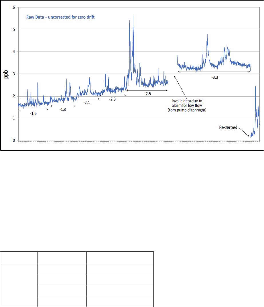
65
Figure 12-3 Zero drift
Baseline drift correction is performed when deemed necessary or when tolerance levels (Table 11-
4a) are exceeded (for readers’ convenience, the table is shown again as Table 12-2).
Generally, data affected by analyzer drift can be corrected by adjusting the data using the multi-
point verification zero-point result. Because drift is not usually constant over time, all zero-check
results should be evaluated to determine the appropriate correction(s) that should be applied.
Excessive drift correction will cause significant uncertainty of the hourly data and possible
invalidation, though longer-term averages may be reasonably accurate.
Table 12-2 Multi-point verification: Zero-point tolerance levels for gas analyzers
Activity Instrument
Tolerance Level
1
Zero point CO 0.08 ppm
NO
X
1.0 ppb
O
3
1.0 ppb
SO
2
0.5 ppb
1 When exceeded, instrument zero adjustment is required.
Note: Frequent adjustment of the instrument should not be necessary and can lead to increased data uncertainty, which usually
indicates instrument issues that need to be addressed
.
Rapid or excessive change in zero is not considered drift and may signal an analyzer malfunction,
which could result in invalid data.

66
Although drifts in span results may be noted, adjustments based on span results are not
recommended. Upscale adjustments should be limited to analyzer calibration against traceable
reference standards.
12.5.7 Below Zero Adjustments
Zero noise is defined as a measure of the deviations from zero while sampling constant zero air
and may result in an instrument reading negative values.
For consistency, 1-hour instrument values that are determined to be valid, even if negative, should
be adjusted to zero (e.g., a valid −1 ppb O
3
should be reported as 0 ppb O
3
).
It is important to distinguish normal instrument noise (refer to instrument manual for
specifications) from instrument malfunction, as data affected by the latter should be invalidated.
Note: Adjustments of negative values to zero should be applied after baseline adjustments are
performed and only applied to 1-hour averages (rather than sub-hourly averages).
Table 12-3 lists the applicable zero adjustment criteria by parameter.
Table 12-3 Zero adjustment criteria
Averaging Interval Parameters Criteria
Sub-hourly all All negative values determined valid shall remain negative prior
to aggregation into hourly averages.
1-hour
PM
2.5
(µg/m
3
)
PM
2.5
value ≥−3 and <0 are adjusted to 0.
PM
2.5
value <−3 are flagged as invalid.
all gases (ppb)
1
Below-zero values
determined valid are adjusted to zero (values
<−3 should be further investigated prior to setting to zero).
1 ppm for CO
12.5.8 Derived Parameter Relationship of NO/NO
2
/NO
X
During data validation, it is important to ensure that expected relationships are preserved. NO
2
is
not measured directly when using a chemiluminescent analyzer, but rather derived from the
difference in measured concentrations of NO
X
and NO in the sample. If adjustments are applied
to NO, NO
2
or NO
X
(e.g., baseline or zero), it will be necessary to apply adjustments to the other
parameters to preserve the relationship where NO + NO
2
= NO
X
.
For analyzers that use a single reaction cell that switches from NO to NO
X
mode (as they are not
measured simultaneously), a ±2 ppb difference is allowed for the 1-hour average of the NO
X
value
compared to the sum of NO and NO
2
values.
As a final note, any technical system audit performed by a third party that identified issues must
67
be addressed prior to finalizing Level 1 validation.
12.6 Level 2 Validation
Level 2 data validation begins with a review of all data and information to confirm that issues
identified during Level 1 have been addressed. The validation process continues by broadening
the analysis to consider additional information obtained from other related data.
Level 2 validation should be performed every 6 to 12 months, reviewing 6 to 12 months of data
and using hourly averaged data.
Two primary types of data are used for this level of validation: dependent data, which are measured
from the same site, and independent data, which are obtained from similar or nearby sites (Figure
12-4).
The next step is to generate summaries in various statistical forms and time-series plots of
dependent data. Plotting data can show relationships that are difficult to detect when reviewing
large amounts of tabular data. Dependent data are used to verify that the data follow expected
behaviour and relationships as well as to screen for outliers (e.g., unusually high or low values that
are not expected at the given site) using defined criteria.
Independent data can be used as an additional check to validate suspect data and assess regional
or similar site-type behaviour. For example, large pollution events such as wildfires could be
identified by examining data on a large regional scale. Data points identified as outliers in Level 1
can be determined valid by citing similar spikes or dips during the same approximate time period
at nearby locations.
Meteorological data (e.g., wind and pollution roses, back trajectories) can also be reviewed to
identify any suspect data.
Some examples of data relationships are listed below:
• O
3
and NO
2
are often inversely correlated. NO reacts quickly with O
3
, which can result
in low O
3
near NO sources (e.g., in urban areas impacted by traffic sources).
• O
3
is formed through photochemical processes in the atmosphere; concentrations often
increase with higher UV and temperature (e.g., diurnal highs towards the latter part of
the afternoon or day, and seasonal highs during spring and summer).
• Pollutant events are often confirmed by examining multiple parameters that may exhibit
similar behaviour and extend over a wide area.
• Pollutant levels might change abruptly if meteorological conditions change (e.g.,
weather fronts, storms, wind direction and speed).
• Pollutant levels surrounding the monitoring site (e.g., spikes in SO
2
) would be expected
only from nearby sources.
Further investigation of suspect data may determine instrument malfunction or other equipment
issues at the site affecting data.
Suspect data and outliers should nevertheless be considered valid unless there is sufficient

68
evidence to invalidate. Justification for decisions regarding validity of suspect data and outliers
should be documented in data validation logs.
Figure 12-4 PM
2.5
data of two buddy sites
12.7 Level 3 Validation
Level 3 validation is defined as a review of validated data by someone independent of both field
operations and the previous data validation process. The intent of this level of review is not to
repeat previous validation tasks, but rather to ensure that data have undergone an independent
review.
The independent reviewer should have extensive knowledge of air pollution and meteorology and
be familiar with the sites to evaluate data based on expected or historical behaviour.
Data reviews performed on an annual basis can identify issues that are not evident on a monthly
basis but become apparent when data are viewed over a longer time period. The reviews should
include at least one year of data, along with comparisons to other existing data sets. Data identified
as suspect should be brought to the attention of the previous data validators for investigation,
modification or justification.
12.8 Post Validation
Regardless of what level of validation is performed, all data should be reviewed by the Network
as a whole at the end of each calendar year. This review can include an inspection of annual plots
and summary statistics (including comparisons to historical mean, maximum and minimum
values). If errors in the data are suspected or discovered, an investigation should be conducted and
data should be corrected as necessary.

69
13.0 DATA COLLECTION AND VALIDATION: INTEGRATED DATA
For integrated methods, samples are collected in the field and analyzed at the NAPS laboratory in
Ottawa using ISO 17025–accredited analytical methods. Validation of these data is performed by
field, laboratory and NAPS data management personnel and requires review of information
generated at every step of the process: sample media preparation, shipping, sampling in the field,
reception and analysis in the laboratory.
Networks participating in the NAPS Program are responsible for sample handling and sampler
calibration and maintenance.
The data collection and validation requirements and recommendations are intended to ensure that
final reported data meet the NAPS Program DQO. Additional detailed procedures are documented
in specific field and lab SOP and methods.
Data verification and validation for integrated samples is a stepwise process that involves
increasingly detailed analysis of the data (Figure 13-1).
Table 13-1 Data verification and validation review
Level
Frequency
Reviewed by
Sample collection as scheduled Network
Level 0 verification upon receipt of sample from field sample-handling lab
Level 1 validation after analytical measurement sample analysis laboratory
Level 2 validation Less than 1 year
sample analysis laboratory and NAPS data
management
Level 3 validation annually or less often NAPS data management

70
Figure 13-1 Data process flow chart for integrated samples
71
13.1 Integrated Sample Metadata
Field metadata specific to integrated samples is important to assess sampler performance and the
conditions under which samples were collected. Metadata are also generated throughout the
laboratory analysis. Defined qualifier codes are assigned to samples and analytical results as
warranted.
13.2 Sample Collection
Collecting integrated samples involves:
• sample media (e.g., filters, cartridges and canisters) preparation in the laboratory
• transportation to the site
• set-up of the samplers and operation on the appropriate date and period
• collection of samples from sites
• transportation to the laboratory.
Sample collection procedures must ensure adequate identification, tracking and sample integrity.
The NAPS laboratory provides datasheets along with the sample media to field personnel. The
sample media is labelled with identification information that must be recorded on the associated
field datasheet.
The following information must be recorded on field datasheets:
• site name and ID number
• sample ID
• sampler type (model, serial number)
• sample type (e.g., routine, duplicate, field blank, travel blank)
• date and time of sampling (both start and end)
• instrument operational parameters (e.g., flow, volume, pressure)
• environmental parameters (e.g., ambient pressure and temperature).
Sample qualifiers recorded at the time of collection can be used by lab personnel to aid in the
verification and subsequent validation of samples.
Examples of sample qualifiers recorded on field datasheets include:
• sampling equipment status (e.g., warnings, malfunctions)
• sampling media not received
• damaged sampling media
• sample duration out of range
• sampling system failed leak or flow check
• environmental events (e.g., fires, construction).
Additional comments related to sample integrity or other sampling conditions (such as unusual
weather) should also be noted on the field datasheets in the appropriate comment section.
It is important that field datasheets are legible and complete and that samples are properly
72
packaged and returned to the lab as soon as possible. Certain sampling media have limited shelf
life and should be used according to the SOP. There may also be sample-specific handling and
shipping procedures to preserve sample integrity.
13.3 Level 0 Verification
Level 0 verification is related to sample integrity upon receipt from the field and prior to analysis.
All samples collected in the field are shipped to the laboratory along with field datasheets. Upon
receipt, samples and paperwork are inspected to verify the following:
• Contamination or damage: Visually assess for damage or potential sample
contamination, and review issues noted on the field datasheets and other issues that may
have arisen during shipment to the lab.
• Documentation completeness: Ensure field datasheets and any other required sample
documentation is present, legible and complete. Follow-up with the Network may be
necessary if questions arise or additional information is required.
• Canister leak checks: Leak checks are performed in the field, but in the case of VOC
canisters, leakage can occur during transit. As a result, canister pressure should be
measured upon receipt and compared to the final sample pressure recorded in the field.
Acceptance criteria should consider the sampling location, as the altitude at which the
sample is collected can differ from the lab, resulting in differences in measured pressure.
• Flow rate and volume: Ensure flow and volume information recorded on the field
datasheet and from instrument readings are within acceptance criteria.
• Sample date and time: Ensure sample was collected on the scheduled date, for the
specified period of time. All times should be in local standard time, and sample dates
should coincide with the applicable NAPS sampling schedule of once every three days
or once every six days.
• Sample shipment and holding time: Ensure sampling holding time criteria, as listed in
method specific SOP, have not been exceeded to help ensure the integrity of the sample.
After a review of field datasheets and other recorded information, samples are assigned qualifier
codes prior to analysis. Certain codes (e.g., damaged or unexposed sample media) will result in a
sample being invalidated and archived with no further analysis performed.
13.4 Level 1 Validation
Following sample verification, valid samples undergo gravimetric and/or chemical analysis.
Subsequently, the laboratory performs Level 1 validation, which generates the analytical results
and includes the following:
• Review of field QC results: Field quality controls include travel and field blanks plus
duplicates that are checks to evaluate sample integrity throughout the sample collection
process.
• Review of laboratory QC results: Laboratory QC checks ensure that equipment is
calibrated and maintained and that methods are followed. These checks include analysis
of lab blanks, instrument calibration, and verification of reagents and calibration
73
standards. Laboratory analysis conditions, such as temperature and humidity constraints,
are important for certain methods. Detailed procedures and acceptable criteria are
specified in lab methods and SOP.
Suspect analytical results are investigated and may require further review of field datasheets and
QC checks. In some cases, reanalysis may be required.
13.5 Level 2 Validation
Level 2 validation is performed by the NAPS laboratory that generated the results and the NAPS
data management, beginning with the review of Level 1 data.
Level 2 validation is to:
• check for outliers
• examine relationships between pollutants
• review summary statistics and compare with historical data.
Examples of Level 2 validation activities include:
• Negative mass: Gravimetric laboratory procedures include equilibration of filters at
controlled conditions of temperature and humidity prior to each weighing, regular use of
reference weights, and filter re-weighing. A negative mass may indicate issues with filter
weighing either before or after the sample is collected.
• Identification of outliers: Data can be reviewed on time-series plots or sorted and
screened to identify suspect data that are unusually high or low for a given pollutant at a
site.
• Expected pollutant relationships: Chemical species may exhibit consistent
relationships with other species. Certain species are expected at higher concentrations
than related species from the same sample (e.g., crustal elements such as iron are
expected to be higher in the coarse fraction than in the fine fraction of ED-XRF samples).
• Complementary measurement checks: In some cases, more than one measurement of
a species is performed on a sample (e.g., metals analyzed by ICP-MS and ED-XRF).
Measurements that do not agree are investigated.
• Reconstructed PM mass balance checks: Reconstructed mass from major chemical
components of a sample is expected to be close to the gravimetric mass measured. This
involves assumptions in mass calculations including particle-bound water.
Reconstructed masses that do not agree with measured mass are investigated (Figure 13-
2).
• Pollutant events: These events are often confirmed by examining multiple species that
may exhibit similar behaviour and extend over a wide area.
• Source-influenced pollutants: Pollutant sources surrounding the monitoring site (e.g.,
spikes in VOC would be expected only from nearby sources).
• Meteorological parameters: Meteorological parameters may impact pollutant levels
(e.g., stagnation events or inversions, temperature, wind direction and speed).

74
Figure 13-2 Reconstructed PM
2.5
mass by major component for the 10 highest
mass days (2012–2015)
During Level 2 validation, data that do not appear representative of the time or place monitored
are investigated. Therefore, when necessary, samples may be reanalyzed in an attempt to rule out
issues with the original analysis.
Suspect data or outliers should nevertheless be considered valid unless there is sufficient evidence
to invalidate. Justification for decisions regarding validity of suspect data or outliers should be
documented in data validation logs.
13.6 Level 3 Validation
Level 3 validation is defined as a review of validated data by someone independent of both field
operations and the laboratory analysis process. The intent of this level of review is not to repeat
previous validation tasks, but rather to ensure that data have undergone an independent review.
The independent reviewer should have extensive knowledge of air pollution and meteorology and
be familiar with the sites to evaluate data based on expected or historical behaviour.
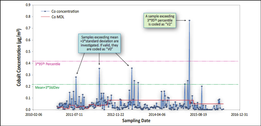
75
Figure 13-3 Cobalt concentrations, 2010–2016
Data reviews performed on a regular basis should include data from at least a one-year period,
along with comparisons to other existing data sets.
Level 3 validation includes:
• screening for outliers and flagging for further investigation (Figure 13-3)
• comparing data sets, including continuous data
• comparing data against similar or nearby sites (“buddy” sites)
• analyzing using other techniques (e.g., statistical tests)
• examining meteorological data.
Data identified as suspect should be brought to the attention of the data originators for
investigation, modification or justification.
13.7 Post Validation
Data are posted on a quarterly basis to the public NAPS Data Products portal. Networks should
review posted data and report issues or inconsistencies to NAPS Data Management. Other data
users may find issues which should also be brought to the attention of NAPS Data Management.
If changes are made to the data, updates will be posted to the portal and reflected in the “change
log” documentation.

76
14.0 REPORTING REQUIREMENTS
14.1 Continuous Data Reporting
For continuous data, Networks are responsible for reporting quality-assured data, as specified in
this Guidance, to NAPS Data Management for archiving in the CWAQD. NAPS Data
Management coordinates continuous data dissemination to the NAPS Data Products portal (Figure
14-1).
Figure 14-1 Continuous data flow
14.1.1 Real-time Reporting of Continuous Data
Networks may make data available to the public in “near real-time.” These data have typically
undergone only the automated screening portion of data verification and should be made available
with disclaimers indicating that data are not fully validated and reviewed.
Networks participate in national and international real-time reporting initiatives such as:
• ECCC’s AQHI: The AQHI is a multi-pollutant index based on the combined
concentrations of PM
2.5
, O
3
and NO
2
. This index was developed through a federal
program coordinated jointly by ECCC and Health Canada and is designed to provide the
public with health-risk information (e.g., low, moderate, high or very high health risk).
ECCC, in partnership with a number of provinces and municipalities, reports AQHI
77
indices on their websites and nationwide through the Government of Canada website.
• Info-Smog: ECCC has been producing daily air quality forecasts and timely smog
warnings for Québec. The Info-Smog Program is available for 95% of Québec’s
population. The index reports on three categories of air quality: good, fair and poor.
When air pollutant concentrations are likely to reach or actually do reach levels harmful
to the health and environment, ECCC issues a smog warning for the affected areas. The
warning is accompanied by advice on protecting health and improving local air quality.
• AirNow: Networks can upload real-time data to the US EPA–sponsored AirNow
website. The AirNow program provides regional summaries and maps with air quality
indices and forecasts using data from participating sites across Canada, the United States
and several countries worldwide.
14.1.2 Continuous Data Reporting to the CWAQD
The CWAQD is the national archive for continuous air pollutants (CO, NO/NO
2
/NO
X
, O
3
, PM
2.5
,
PM
10
and SO
2
). Networks transfer their validated data to NAPS Data Management. Data transfer
usually occurs annually (six months after calendar year-end) by File Transfer Protocol (FTP) or e-
mail (for small data sets). Acceptable file formats are flat files (.xlsx or .csv), DR DAS custom and
XML formats.
Final validated data should be submitted in hour-ending average format (e.g., minute data collected
between 01:01 and 02:00 are averaged and reported as the 02:00 hour), in local standard time, with
no adjustment for daylight saving time. All hourly data should be reported to at least 5 decimal
places.
Invalid and missing data are noted with a flag and/or a -9999 value as defined in the transfer
method SOP.
Data in the CWAQD should always reflect the most current validated data. Changes to data should
be resubmitted to NAPS Data Management by the Network and documented by both.
14.1.3 Posting Continuous Data to the NAPS Data Portal
Data received from Networks, from the previous calendar year, are prepared by NAPS Data
Management and posted to the NAPS data portal in the form of hourly data and statistical summary
files. Preliminary data are posted after Networks’ submissions are compiled (late summer). A final
version is posted after further review (by the end of the calendar year).
Detailed information on the format and the use of these files is available on the NAPS Data portal
home page.
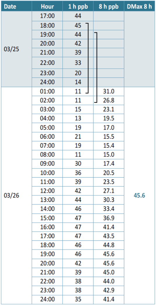
78
Data summaries are also reported for
various averaging periods and statistical
forms, including: 1-hour, 8-hour, 24-
hour, daily maximum 1-hour, daily
maximum 8-hour and daily means. 8-
hour means are running 8-hour averages
for each hour of the year, with the result
reported for the end hour (Figure 14-
2). Daily maximum 8-hour values are
the maximum 8-hour mean values for
each day of the year. 24-hour means are
running 24-hour averages for each hour
of the year, with the result reported for
the end hour. Daily means are based on
the average hourly concentrations
recorded from 01 to 24 hours.
Figure 14-2 Calculation of Daily Maximum
8-hour Ozone

79
Table 14-1 Required significant figures and units by parameter
Parameter
Averaging
time
Minimum
significant figures and units
1
CO
1
hour
0.01 ppm
NO/NO
2
/NO
X
1
hour
1 ppb
O
3
1
hour
1 ppb
SO
2
1
hour
0.1 ppb
PM
2.5
1
hour
1 µg/m
3
at actual temperature and pressure
1 Rounding convention: for digits ≥ 5, round up to the nearest required significant figure; for digits < 5, round down to the nearest required
significant figure (e.g., 4.5 rounds to 5 and 4.4 rounds to 4).
14.2 Integrated Data Reporting
The NAPS Data Management coordinates integrated data dissemination to the NAPS Data portal
(Figure 14-3).
Figure 14-3 Integrated data flow
14.2.1 Integrated Data Reporting to the CWAQD
The NAPS Laboratory reports all sample information, analysis results and qualifier codes to NAPS
Data Management. They are responsible for storing all sample information in the CWAQD as well
as reporting validated data to the public.
80
The NAPS Laboratory also reports sample information (metadata) to NAPS Data Management.
These reports contain:
• sample site ID
• sampling date, time and volume
• information on the sampling media and equipment
• all field and sampling lab information and qualifier codes.
The NAPS laboratory reports Level 1 validated data to NAPS Data Management. These reports
also contain:
• information about sample preparation
• analytical method and equipment
• qualifier codes associated with the analysis.
The NAPS Data Management loads the reports into the CWAQD. At this point, NAPS Data
Management collaborates with the NAPS Laboratory to conduct Level 2 validation of the data.
14.2.2 Integrated Data Reporting to the NAPS Data Portal
On a quarterly basis, NAPS Data Management reports Level 3 validated data, including associated
validation codes, to the NAPS Data Products portal.
Integrated data are posted in Excel files to the portal by year. Detailed information on the format
and the use of these files is available on the NAPS Data Products portal.
14.3 Other NAPS Data Reporting Requirements
NAPS data support air management policies and reporting obligations under major national and
international air quality agreements such as the Canadian AQMS and the Ozone Annex to the 1991
Canada-US Air Quality Agreement. Data provided by NAPS support public information tools on
air quality conditions, including governments’ air quality websites, CESI and the US AirNow
mapping site. Data are also used to track trends in ambient air quality in communities (urban and
rural) across the country; support health and environmental research and analysis; conduct
environmental assessments; verify emissions inventories; conduct source apportionment analysis;
validate and calibrate air quality models, remote sensing and air quality forecasting; and develop
and assess new monitoring technologies.
NAPS data support ECCC’s risk management, monitoring and enforcement actions for targeted
chemicals under the Chemicals Management Plan and CEPA. The NAPS Program has a large
number of clients from government, consulting groups, Canadian and international non-
governmental organizations, industry, academia, media and the public.
Below are some examples of reporting obligations that use NAPS data.
81
14.3.1 Data Reported to the Canadian Environmental Sustainability Indicators (CESI)
The CESI Program provides data and information to track Canada’s performance on key
environmental sustainability issues, including climate change and air quality, water quality and
availability, and protection of nature.
Air quality indicators have been developed at the national, regional and station level. These
indicators are a means to present the state of air quality and trends across Canada on an annual
basis using data collected from the NAPS Program.
14.3.2 Ozone Annex to the 1991 Canada-US Air Quality Agreement
Beginning in 2002, as part of biennial progress reports, Canada and the United States agreed to
provide the following ambient air quality information:
• ambient O
3
concentration trends, reported in the form of the applicable standards
• ambient VOC concentration trends
• ambient NO
X
concentration trends.
Ambient air quality information is reported for all relevant monitors located within 500 km of the
border between Canada and the lower 48 states of the United States.
14.3.3 Air Quality Management System (AQMS)
In October 2012, jurisdictions, with the exception of Québec, agreed to begin implementing a new
AQMS. Québec supports the general objectives of AQMS and is collaborating with jurisdictions
on developing other elements of the system, notably air zones and airsheds. AQMS provides a
comprehensive framework for collaborative action across Canada to further protect human health
and the environment from harmful air pollutants through continuous improvement of air quality.
The key elements of AQMS include new CAAQS, active air quality management at the local and
regional levels, industrial emissions requirements for industrial sectors and equipment groups, and
intergovernmental collaboration to reduce mobile source emissions (Figure 14-4).
CAAQS are established with the goal of protecting human health and the environment. They are
intended to drive continuous air quality improvement across Canada.
The air quality data collected by the NAPS Program are used by governments to assess and report
on air quality and develop programs to address priority air quality issues in air zones as part of
AQMS.

82
Figure 14-4 Air Quality Management System
14.3.4 NAPS Annual Data Summary Reports
NAPS started publishing annual data summaries in 1972. NAPS Data Management continues to
publish annual data summaries on national air quality to the NAPS Data Products portal.
15.0 ASSESSMENTS AND CORRECTIVE ACTION
This Guidance is intended to assist Networks in developing and implementing QA/QC for their
ambient air monitoring program. By following these guidelines, the NAPS DQO should be met.
Routine assessments of network operations provide assurance that the monitoring systems and data
management procedures are of sufficient quality to meet NAPS DQO, and they identify where
improvements might be necessary (Table15-1).
Types of assessments performed in the NAPS Program include:
• Performance and systems audits that are conducted either by ECCC auditors or other
organizations and that are separate from the host operating Network.
• The NAPS Inter-agency Measurement Study, in which participants analyze an unknown
sample gas concentration provided by the NAPS Applied Metrology Laboratory.

83
• DQA, which involve the statistical analysis of air quality data to determine if reported
data are meeting program objectives and DQO.
Note that audits and assessments of the NAPS Laboratory for analysis of integrated samples
include:
• performance and systems audits by accredited bodies
• participation in blind sample tests and round robins with independent labs.
Table 15-1 ECCC audit and assessment schedule
Assessment type Frequency
Performance or systems audit every 2 years at selected sites (per Network)
1
NAPS Inter-agency Measurement Study every 3 years
DQA annually
1
Number of sites will depend on time and resources available and may be performed upon request by a Network.
15.1 Performance and Systems Audits
Performance and systems audits are independent evaluations of data quality. A systems audit
reviews the entire monitoring system documentation and procedures for the station siting,
instrumentation calibration and maintenance, and data collection and validation. A performance
audit focusses on station operation (e.g., instrument performance, inlet manifold, siting,
maintenance, safety). These audits can be performed either independently or concurrently.
The Network should ensure that all site documentation is readily available (e.g., NQAP, SOP, field
and QC records) and should ensure that all sites, instruments and data collection systems are easily
and safely accessible. Discussions prior to the audit are useful for reviewing schedules and
anticipated activities, and for addressing preliminary questions.
Prior to a scheduled ECCC audit, the Network will receive a letter and a questionnaire. The auditors
will use the responses to familiarize themselves with individual site specifications and to better
prepare for the audit. Example questionnaires are included in Appendix C.
A post-audit meeting to review major findings and corrective actions may be required. It should
involve ECCC auditors and Network personnel (e.g., personnel from field operations, QA/QC,
data management and reporting).
Specific components of both performance and systems audits are discussed below.
15.1.1 Performance Audit
Performance audit procedures are instrument-specific and generally follow procedures used for
verification and calibrations. These include multi-point checks for gas analyzers and flow checks
for continuous PM and integrated samplers.
84
The following are important considerations for performance audits:
• no adjustments should be made to the measurements system prior to the audit
• audit gases and measurement devices must be certified against the NAPS reference
standards or other NIST traceable sources
• instrument readings should be stable before being recorded
• readings should be recorded from the data collection system and verified against the
analyzer’s display to ensure that readings are comparable.
Performance is evaluated by comparing audit results with the NAPS acceptance criteria (Section
11.0). To facilitate comparisons, an Excel workbook template is available for download from the
NAPS document-sharing website. This workbook includes instrument-specific spreadsheets that
calculate the differences between readings and reference standards, providing a pass/fail
indication. Audit results that do not meet the acceptance criteria should be addressed by the
Network and may require corrective action.
15.1.2 Systems Audit
A systems audit is primarily an administrative review of all documentation for the entire
monitoring process to ensure that the Network is following procedures outlined in this Guidance
and in the Network’s NQAP.
An example of a system audit is available in Appendix C.
15.1.3 Audit Response
Within 30 days of an ECCC audit, auditors will provide a summary report to the Network. The
report will include:
• audit date and site name
• audit team members
• Network staff involved in station operation
• summary and conclusions regarding audit results, required corrective actions and
recommended improvements
• attachments or appendices that include audit results or performance evaluation
spreadsheets used.
Within 90 days of receiving the audit report, the Network will provide an audit summary response
that includes a plan to address findings and issues highlighted in the report. Findings that may
compromise data quality or indicate that an instrument is not meeting acceptance criteria should
be addressed as soon as possible to avoid data loss.
If the Network disputes any audit findings, the response should provide a detailed justification or
rationale. All documentation of audits, including any findings, corrective actions, disputes and
resolutions should be kept on file.
85
15.2 Inter-Agency Measurement Study
The NAPS Applied Metrology laboratory coordinates an inter-agency comparison study. The
objective of the inter-agency measurement study is to provide information on the accuracy and
method bias of the calibration systems used across the network.
For this study, gas cylinders containing an unknown concentration of NO, SO
2
or CO are sent to
participants for analysis. Written procedures are also provided and should be followed closely to
help ensure consistent application of the tests across participants.
After analyzing the cylinder, participants should return results and information promptly. The
reference gas concentration in the cylinder is verified against primary standards at the NAPS
Applied Metrology laboratory and is the average of all measured concentrations before and after
testing by participants. For this study, values are expected to be within ±4% of the reference
concentration.
Participants are contacted with the test results within 30 days after the return of the cylinder.
Results outside of the ±4% limit should trigger an investigation and possible corrective action.
The final report summarizes the results from all participants.
15.3 Data Quality Assessments (DQA)
DQA involve the statistical analysis of air quality data to help determine if reported data meet
NAPS DQO. These assessments can help Networks evaluate overall systems performance and
revise guidelines or objectives as necessary.
Assessments may include:
• Network Data Quality Reports
o Precision and bias: estimates both bias and precision derived from the daily
or weekly QC checks results for the four continuous gaseous methods (CO,
NO
X
, O
3
, and SO
2
). These reports should be aggregated for each method, for
all methods at each site and for the Network as a whole. Summaries should
also include annual QC checks completeness
o Continuous PM performance: estimates instrument performance using the
results from the flow rate QC checks and leak checks. Summaries should also
include annual QC checks completeness
o Annual data completeness: includes percent completeness for each
continuous method per site. Data completeness information accompanies the
pollutant-specific annual summary files available on the NAPS Data portal.
• ECCC Reports
o Five-year NAPS audit summary report summarizing audit results by
parameters and for all provinces and territories.
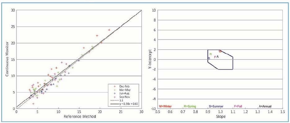
86
• ECCC and Network data Reports
o Data comparisons such as between continuous PM
2.5
FEM versus integrated
NAPS RM (Figure 15-1).
The assessments can help inform either the need for corrective action, or a reassessment of DQO
for future updates of the Guidance.
Figure 15-1 Collocated PM
2.5
continuous monitor vs NAPS RM measurements

87
REFERENCES
Brauer, M., and Hystad, P. 2012. Developing a Monitor Classification System for the National Air Pollution
Surveillance System. University of British Columbia School of Environmental Health and School of
Population and Public Health. Report to Environment Canada, Ottawa.
Brauer, M., Hystad, P., and Cervantes, A. 2013. Refining the NAPS Monitor Classification, Extending It to Inform
Population Exposure Assessment, and Identifying High-Traffic Air Pollution Locations in Vancouver.
University of British Columbia School of Environmental Health and School of Population and Public Health.
Report to Environment Canada, Ottawa.
Brauer, M., Hystad, P., and Poplawski, K. 2011. Assessing the Spatial Representativeness of PM
2.5
and O
3
Measurements from the National Air Pollutant Surveillance System. University of British Columbia School
of Environmental Health and School of Population and Public Health. Report to Environment Canada,
Ottawa.
Canadian Council of Ministers of the Environment. 2011. Ambient Air Monitoring Protocol for PM
2.5
and Ozone.
Available online: www.ccme.ca
.
Environment Canada. 2004. National Air Pollution Surveillance Network Quality Assurance and Quality Control
Guidelines. Report No. AAQD 2004-1. Environment Canada Analysis and Air Quality Division, Ottawa.
Evans, G.J., Jeong, C.-H., Sabaliauskas, K., Jadidian, P., Aldersley, S., Larocque, H., and Herod, D. 2011. Design of
a Near-road Monitoring Strategy for Canada. Southern Ontario Centre for Atmospheric Aerosol Research.
Report produced for Environment Canada, Ottawa.
Health Effects Institute. 2010. Traffic-related Air Pollution: A Critical Review of the Literature on Emissions,
Exposure, and Health effects. Final Version of Special Report No. 17. Health Effects Institute, Boston.
Available online: http://pubs.healtheffects.org/view.php?id=334
(viewed 2017-04-17).
RWDI Consulting Engineers and Scientists. 2016. Recommendations on Siting Criteria for SO2 Air Quality
Monitoring. Conducted under the National Air Pollution Surveillance (NAPS) Program. Environment
Canada Contract # 3000601059.
Statistics Canada. 2017a. Dictionary, Census of Population. 2016. Statistics Canada catalogue no. 98-301-X. Ottawa.
Ottawa. http://www12.statcan.gc.ca/census-recensement/2016/rt-td/population-eng.cfm
(viewed 2017-06-
22).
Statistics Canada. 2017b. The Daily, Wednesday, February 8, 2017. Component of Statistics Canada catalogue no.
11-001-X. Ottawa. Ottawa. http://www.statcan.gc.ca/daily-quotidien/170208/dq170208a-eng.htm
(viewed
2017-06-22).
U.S. Department of Transportation, Federal Highway Administration. 2014. Traffic Monitoring Guide. Chapter 1
Traffic Monitoring Theory, Technology and Concepts. Available online:
https://www.fhwa.dot.gov/policyinformation/tmguide/tmg_2013/traffic-monitoring-theory.cfm
(viewed
2018-04-30).
U.S. EPA (U.S. Environmental Protection Agency). 1997. Guidance for Network Design and Optimum Site Exposure
for PM
2.5
and PM
10
. Office of Air Quality Planning and Standards, December 1997. Available online:
www.epa.gov/ttnamti1/files/ambient/pm25/network/r-99-022.pdf
(viewed 2017-04-17).
U.S. EPA. 2006. Title 40 Code of Federal Regulations (CFR) Part 53, Ambient Air Monitoring Reference and
Equivalent Method. Available online: https://www3.epa.gov/ttnamti1/files/ambient/pm25/pt5006.pdf
(viewed 2017-06-07).
U.S. EPA. 2018. List of Designated Reference and Equivalent Methods. Available online:
www.epa.gov/ttn/amtic/criteria.html
(viewed 2017-06-11).

88
APPENDIX A – AMBIENT AIR MONITORING EQUIPMENT

89
APPENDIX B – NAPS METHOD AND SOP REFERENCE LIST
Methods and SOP are listed here for reference purposes. Updates are implemented regularly, and
this list follows the latest revisions of the documents. The NAPS document sharing website should
be referred to for the most complete current list.
Table B-1 NAPS Operations methods and SOP
Field methods and SOP
Continuous instrument operation
Title
Author
Continuous Measurement of Ozone in Ambient Air by Ultraviolet (UV) Photometry
ECCC,
NAPS Operations
Operating Procedures for BAM
-1020 PM
2.5
Monitors in the NAPS Network
ECCC,
NAPS Operations
National Air Pollution Surveillance (NAPS) Network RM for the Measurement of
PM
2.5
Concentration in Ambient Air Using Filter Collection and Gravimetric Mass
Determination
ECCC, AAQS, AQRD
Continuous Measurement of Carbon Dioxide (CO) in Ambient Air by Nondispersive
Infrared Photometry with Gas Filter Correlation (GFC)
ECCC,
NAPS Operations
Continuous Measurement of Nitrogen Dioxide (NO
2
) in Ambient Air by
Chemiluminescence
ECCC, NAPS Operation
Continuous Measurement of Sulphur Dioxide (SO
2
) in Ambient Air by Ultraviolent
(UV) Fluorescence
ECCC,
NAPS Operations
Thermo
Synchronized Hybrid Ambient Real-time Particulate (SHARP5030) Monitor
Operating Instructions
ECCC,
NAPS Operations
Manual/
integrated instrument operation SOP
Title
Author
Partisol 2000i
-D Dichotomous Operating Instructions
ECCC,
NAPS Operations
Dichotomous Partisol
-Plus model 2025 Sequential Air Sampler
ECCC,
NAPS Operations
Met One Super SASS
-Plus Operating Instructions
ECCC,
NAPS Operations
Operating Instructions for RM Environmental VOC Sampler Model 910C with
sequential 912
ECCC,
NAPS Operations
Operating Procedure of Model 926 Carbonyl
Sampler
ECCC,
NAPS Operations
Environment Canada PUF Sampler Instructions
ECCC,
NAPS Operations

90
Data
management SOP
Title
Author
Standard Operating Procedure for NAPS FTP
ECCC, NAPS
data
m
anagement
Sample
management
Title
Author
Procedures for
Preparing and Receiving PAH Canisters and Filters
ECCC, AAQS, AQRD
Determination of the Weight of Particulate Matter Collected on Teflon® Membrane
Filters
ECCC, AAQS, AQRD
Preparation, Shipping, and Unloading of ChemComb Cartridges
ECCC, AAQS, AQRD
VOC Sample Management Procedures
ECCC, AAQS, AQRD

91
APPENDIX C – TECHNICAL SYSTEMS AUDIT QUESTIONNAIRES
a) Network
(Attach organization flow chart if available)
KEY INDIVIDUALS
PROVINCIAL/TERRITORIAL NATIONAL AIR
POLLUTION SURVEILLANCE PROGRAM (NAPS)
MANAGERS:
QUALITY ASSURANCE OFFICER:
FIELD OPERATIONS CO-ORDINATOR:
DATA CO-ORDINATOR/ANALYSTS:
FIELD OPERATORS:
COMMENTS:
KEY RESPONSIBILITIES
ACTIVITY
RESPONSIBLE PARTY
INSTRUMENT REPAIR
CERTIFICATION OF STANDARDS (PROTOCOL GAS,
FLOW STANDARDS, ETC)
DATA VERIFICATION AND REDUCTION
COMMENTS:

92
b) Site and system design
SITE SPECIFICATIONS
SITE NAME
SITE NUMBER/ID
SITE ADDRESS
CITY, PROVINCE
SITE COORDINATES
(WGS84 DATUM)
LATITUDE (DECIMAL DEGREES): LONGITUDE (DECIMAL DEGREES):
ELEVATION (M):
LIST OF MONITORED
POLLUTANTS:
NAPS PARAMETERS:
NON-NAPS PARAMETERS:
DISTANCE TO
NEAREST ROADWAY
NEAREST
NAPS SITE CLASSIFICATION
URBANIZATION o LARGE o MEDIUM o SMALL o NON-URBAN
NEIGHBOURHOOD
POPULATION
o < 500 o 500–9,999 o 10,000–49,999 o 50,000–99,999
o 100,000–149,999 o > 149,999
LOCAL LAND USE o RESIDENTIAL o AGRICULTURAL o OPEN o FORESTED
o COMMERCIAL o INDUSTRIAL o PARKS o WATER
SITE TYPE o GENERAL POPULATION EXPOSURE o REGIONAL BACKGROUND
o POINT SOURCE–INFLUENCED o TRANSPORTATION-SOURCE INFUENCED
PROVIDE A MAP OF SITE AND SURROUNDING TERRAIN AND FEATURES
PROVIDE RECENT SITE PHOTOGRAPHS (ALL QUADRANTS FROM THE SITE AND LOOKING AT THE
SITE)
COMMENTS:

93
INSTRUMENT INFORMATION
MANUFACTURER
MODEL
SERIAL NUMBER
HEIGHT OF
INLET
ABOVE
GROUND (M)
HEIGHT OF INLET
ABOVE ROOF TOP
(M)
UNRESTRICTED
AIRFLOW IN AT LEAST 3
QUADRANTS
(YES, NO)
SAMPLING INLET SYSTEM/MANIFOLD DESIGN
BRIEFLY DESCRIBE THE SAMPLE
MANIFOLD TYPE USED.
WHAT IS THE RESIDENCE TIME?
WHAT MATERIAL IS USED FOR
SAMPLING LINES?
WHAT IS THE HEIGHT OF THE
SAMPLING INLET?
YES
NO
COMMENT
IS MANIFOLD EQUIPPED WITH A
BLOWER/PUMP?
HOW IS THE AIR FLOW THROUGH
THE MANIFOLD VERIFIED?
COMMENTS:

94
c) Documentation and records
QUALITY ASSURANCE PROJECT PLAN (NQAP)
TITLE AUTHOR
DATE OF LAST
NQAP REVIEW
DATE OF LAST
NQAP REVISION
COMMENTS:
STANDARD OPERATING PROCEDURES (SOP)
TITLE AUTHOR DATE OF LAST
SOP REVIEW
DATE OF LAST
SOP REVISION
COMMENTS:

95
NETWORK
DOCUMENTATION
ARE EACH OF THE FOLLOWING SITE REQUIREMENTS DOCUMENTED IN A NETWORK MONITORING
PLAN OR NQAP OR OTHERWISE AVAILABLE AS OFFICIAL RECORDS?
YES
NO
COMMENT
STREET ADDRESS AND GEOGRAPHIC
COORDINATES?
MONITORED
POLLUTANTS
PHOTOGRAPHS OF EACH SITE AND ITS
ASSOCIATED CARDINAL VIEWS?
START
-UP AND SHUTDOWN DATES?
DOCUMENTATION OF INSTRUMENTATION
AND MAINTENANCE RECORDS?
WHO HAS CUSTODY OF CURRENT
NETWORK DOCUMENTS?
NAME: TITLE:
HOW OFTEN IS
NETWORK SITING
REVIEWED?
FREQUENCY:
COMMENTS:
d) Routine operation
SITE MAINTENANCE
ON AVERAGE, HOW OFTEN ARE SITES
VISITED?
ON AVERAGE, HOW MANY SITES DOES A
SINGLE OPERATOR HAVE RESPONSIBILITY
FOR?
WHAT IS YOUR SCHEDULE FOR CLEANING
MANIFOLDS?

96
WHAT IS USED TO PERFORM THE
CLEANING?
YES
NO
COMMENT
IS THERE A CONDITIONING PERIOD FOR
THE MANIFOLD AFTER CLEANING?
AT WHAT FREQUENCY ARE LINES
CHANGED?
AT WHAT FREQUENCY ARE PARTICULATE
FILTERS FOR GAS ANALYZERS REPLACED?
YES
NO
COMMENT
DO SITES EMPLOY UNINTERRUPTABLE
POWER SUPPLY (UPS) DEVICES?
EQUIPMENT MAINTENANCE AND REPAIR
WHO IS RESPONSIBLE FOR
MAINTENANCE AND REPAIRS?
YES
NO
COMMENT
IS TRAINING PROVIDED?
IS ANY ONGOING TRAINING
AVAILABLE/PROVIDED?
WHERE IS MAINTENANCE PERFORMED?
•
FIELD STATION
•
HEADQUARTERS
•
SENT TO MANUFACTURER (AT THE DIRECTION OF
EC NAPS)
•
SENT TO EC NAPS
DESCRIBE ADEQUACY AND
AVAILABILITY OF SPARE PARTS,
INSTRUMENTS AND TOOLS.
ARE MANUALS AND METHOD SOP
AVAILABLE TO THE OPERATOR TO
PERFORM ANY NECESSARY
MAINTENANCE OR REPAIR?

97
FIELD
DOCUMENTATION
WHAT TYPE OF LOGS ARE MAINTAINED
FOR THIS SITE?
(E.G., MAINTENANCE, CALIBRATION, SITE
CONDITION/ MAINTENANCE,
INSTRUMENTS)
INDICATE IF ELECTRONIC (E) OR PAPER
(P)
WHO REVIEWS AND VERIFIES THE LOGS
FOR ADEQUACY OF INFORMATION
ENTERED?
HOW IS CONTROL OF LOGS MAINTAINED?
ARE THE COMPLETED LOGS ARCHIVED?
IF SO WHERE?
WHAT OTHER RECORDS ARE USED?
YES NO COMMENT
ZERO SPAN RECORD?
GAS USAGE LOG? ADD DETAILS
CAL/SPAN, EXPIRY DATES, ETC
MAINTENANCE LOG?
RECORD OF AUDITS?
ARE CALIBRATION RESULTS AVAILABLE
TO FIELD OPERATORS?
PROVIDE EXAMPLE FIELD VERIFICATION/
CALIBRATION WORKSHEETS

98
e) Verification and calibration/QC checks
MULTI-POINT VERIFICATION/CALIBRATION FREQUENCY (FIELD INSTRUMENTS)
INSTRUMENT
ZERO/SPAN CHECK TYPE
(INTERNAL, WITH CALIBRATOR, ETC)
FREQUENCY
COMMENTS:
TRACEABILITY
OF CALIBRATION AND TRANSFER STANDARDS
YES
NO
COMMENT
ARE ALL FLOW-MEASUREMENT
TRANSFER STANDARDS CERTIFIED?
FREQUENCY OF CERTIFICATION? BY
WHOM?
ARE ALL GAS CYLINDERS CERTIFIED?
FREQUENCY OF CERTIFICATION? BY
WHOM?
ARE ALL DILUTION CALIBRATORS
CERTIFIED?
FREQUENCY OF CERTIFICATION? BY
WHOM?
ARE ALL RELATIVE HUMIDITY TRANSFER
STANDARDS CERTIFIED?
FREQUENCY OF CERTIFICATION? BY
WHOM?
ARE ALL TEMPERATURE TRANSFER
STANDARDS COMPARED?
(TEMPERATURE PROBE ON DELTACAL)
FREQUENCY OF
CERTIFICATION? BY
WHOM?
WHERE DO FIELD OPERATORS OBTAIN
GASEOUS STANDARDS?
ARE COPIES OF CERTIFICATIONS OF ALL
STANDARDS CURRENTLY IN USE
READILY AVAILABLE TO QUALIFIED FIELD
TECHNICIANS?
WHO IS RESPONSIBLE FOR MAINTAINING
FIELD TRANSFER
STANDARDS?
COMMENTS:

99
f) Data collection and management
SOFTWARE DOCUMENTATION
YES NO COMMENT
DOES DOCUMENTATION EXIST FOR ALL
DATA PROCESSING SOFTWARE?
IS SOFTWARE PURCHASED, WRITTEN IN
HOUSE, OR PURCHASED, WITH
MODIFICATIONS IN HOUSE?
SOFTWARE TITLE:
DATE OF LATEST VERSION:
YES
NO
COMMENT
IS A USER MANUAL AVAILABLE TO DATA
MANAGEMENT PERSONNEL FOR ALL
SOFTWARE CURRENTLY IN USE?
ARE COMPUTER SYSTEM CONTENTS
BACKED UP REGULARLY?
WHAT IS THE RECOVERY CAPABILITY?
(HOW MUCH TIME AND DATA WOULD BE LOST)
YES
NO
COMMENT
ARE COMPUTER SYSTEM CONTENTS
BACKED UP REGULARLY?
ARE THESE TESTS DOCUMENTED?
HOW ARE SOFTWARE VERSIONS TRACKED?
YES
NO
COMMENT
IS A UNIQUE LOG-IN REQUIRED FOR
PROGRAMS WHERE DATA CAN BE
CHANGED?
ARE RAW VALUES MAINTAINED WITHIN
THE DATA MANAGEMENT SYSTEM?
IS THERE A PROCESS IN PLACE FOR
ADJUSTING DATA WHERE NEEDED?
DOES THE DATA MANAGEMENT SYSTEM
SUPPORT THE FUNCTIONALITY FOR
VALIDATION BY MULTIPLE USERS WITH
DIFFERENT LEVELS OF REVIEW?
COMMENTS:

100
DATA COLLECTION (CONTINUOUS DATA)
YES NO COMMENT
DO YOU FOLLOW A PRESCRIBED
PROCEDURE, DESCRIPTION, OR A
CHART THAT SHOWS A COMPLETE DATA
FLOW FROM POINT OF ACQUISITION TO
POINT OF SUBMISSION? IF YES,
IDENTIFY THE AUTHOR.
ARE DATA HANDLING PROCEDURES
DOCUMENTED FOR DATA FROM
CONTINUOUS ANALYZERS?
INDICATE BELOW THE FORMAT AND MEDIUM OF DATA SUBMITTED TO THE DATA PROCESSING SECTION
REPORTING NETWORK
DATA MEDIUM
FORMAT
HOW ARE RAW DATA RECORDS ARCHIVED AT THE SITE?
DESCRIBE ALL FIELDS THAT ARE INCLUDED WITH RAW DATA (FLAGS, DIAGNOSTICS,
VERIFICATION/CALIBRATION RESULTS, ETC.)
HOW OFTEN ARE DATA RECEIVED AT THE PROCESSING CENTRE FROM THE FIELD SITES AND
MONITORING NETWORK?
HOW ARE THE DATA ENTERED INTO THE DATA MANAGEMENT SYSTEM? MANUAL OR AUTOMATED
TRANSCRIPTION?
HOW ARE DATA STORED AT THE PROCESSING CENTRE?
HOW FAR BACK ARE DATA STORED?
WHAT METADATA ARE STORED IN THE DATA MANAGEMENT SYSTEM?
ARE DATA SCREENED AGAINST USER-DEFINED RULES AND ACCEPTANCE CRITERIA WHEN LOADED
INTO THE DATA MANAGEMENT SYSTEM?
HOW ARE YOU ALERTED TO AN INSTRUMENT MALFUNCTION?

101
IS THERE DOCUMENTATION ACCOMPANYING THE DATA REGARDING ANY MEDIA CHANGES,
TRANSCRIPTIONS, AND/OR FLAGS THAT HAVE BEEN PLACED INTO THE DATA BEFORE DATA ARE
RELEASED TO THE PROCESSING CENTER? DESCRIBE.
IS THERE A PROCESS IN PLACE TO VERIFY THE TIME-STAMP
ASSOCIATED WITH EACH DATA RECORD
IS ACCURATE?
DATA VALIDATION AND CORRECTION (CONTINUOUS DATA)
YES NO COMMENT
DO DATA VALIDATION GUIDELINES EXIST
THAT OUTLINE THE VALIDATION
PROCESS?
ARE FIELD LOGBOOKS OR SITE
OPERATOR INPUT USED DURING THE
DATA VALIDATION PROCESS?
IF YES, HOW IS THIS INFORMATION USED
IN TERMS OF DATA VALIDITY?
HOW MANY DATA REVIEW STEPS EXIST?
WHO IS RESPONSIBLE FOR EACH STEP?
IS THERE A REQUIREMENT FOR THE
MINIMUM NUMBER OF DATA POINTS THAT
ARE NEEDED TO CREATE A VALID
HOURLY AVERAGE?
HAVE VALIDATION CRITERIA, APPLICABLE
TO ALL DATA PROCESSED BY THE
REPORTING NETWORK, BEEN
ESTABLISHED AND DOCUMENTED?
IF YES, INDICATE DOCUMENT WHERE
SUCH CRITERIA CAN BE FOUND (TITLE,
REVISION DATE).
ARE ZERO/SPAN RESULTS OR OTHER
CALIBRATION DIAGNOSTICS FLAGGED BY
THE DATALOGGER?
ARE AMBIENT DATA CORRECTED BASED
ON ZERO/SPAN RESULTS?
IF SO, PLEASE DESCRIBE:
DO DOCUMENTED DATA VALIDATION CRITERIA ADDRESS LIMITS FOR THE FOLLOWING AND IS THERE
A PLAN IN PLACE IF ACCEPTANCE CRITERIA ARE NOT MET?
OPERATIONAL PARAMETERS SUCH AS
STATION TEMPERATURE, RANGE TESTS
AND/OR FLOW RATES

102
ZERO/SPAN CHECKS FOR GASEOUS
ANALYZERS
OTHER CHECKS UNIQUE TO A
MEASUREMENT SYSTEM (FLOW,
TEMPERATURE, PRESSURE, ETC.)
OUTLIER TESTS AS PART OF THE
SCREENING PROCESS
MANUAL DATA CHECKS
ARE THERE METRICS IN PLACE TO
COMPARE VALIDATED DATA TO DATA
QUALITY OBJECTIVES?
ARE CHANGES TO THE DATA
DOCUMENTED?
HOW ARE DATA MARKED AS INVALID?
ARE JUSTIFICATIONS FOR INVALIDATING
DATA DOCUMENTED?
ARE CHANGES PERFORMED ACCORDING
TO CURRENT SOP OR NQAP?
IF NOT, DESCRIBE:
WHO HAS AUTHORITY FOR APPROVING CORRECTIONS?
HOW ARE THESE CORRECTIONS DOCUMENTED?
ARE DATA VALIDATION SUMMARIES
PREPARED AT EACH CRITICAL POINT IN
THE MEASUREMENT PROCESS OR
INFORMATION FLOW AND FORWARDED
WITH THE APPLICABLE DATA SET TO THE
NEXT LEVEL OF VALIDATION?
PLEASE INDICATE THE POINTS WHERE
SUCH SUMMARIES ARE PERFORMED
ARE DATA EVER DELETED?
IF YES, WHAT CRITERIA ARE APPLIED FOR
DATA TO BE DELETED?
WHAT CRITERIA ARE APPLIED TO CAUSE DATA TO BE REPROCESSED?
ARE GROUPS SUPPLYING DATA
PROVIDED AN OPPORTUNITY TO REVIEW
DATA AND CORRECT ERRONEOUS
ENTRIES?
IF YES, HOW?

103
ARE ZERO/SPAN AND VERIFICATION/
CALIBRATION DATA REVIEWED AS PART
OF THE VALIDATION PROCESS?
DO DATA VALIDATION ACCEPTANCE
CRITERIA EXIST FOR THESE CHECKS?
DESCRIBE THE DATA HANDLING PROCESS WHEN THESE CHECKS ARE OUTSIDE
OF ACCEPTABLE LIMITS:
ARE ZERO/SPAN AND
VERIFICATION/CALIBRATION DATA
CHECKED PRIOR TO SUBMISSION?
IS A FINAL DATA PROCESSING CHECK
PERFORMED PRIOR TO SUBMISSION OF
ANY DATA?
ARE CALIBRATION AND/OR AUDIT
RESULTS REVIEWED AS PART OF THE
VALIDATION PROCESS?
WHO IS RESPONSIBLE FOR REVIEWING
THESE RESULTS AND DETERMINING DATA
VALIDITY?
DESCRIBE THE VALIDATION PROCESS FOLLOWED IF THESE CHECKS ARE OUTSIDE OF VALIDATION
ACCEPTANCE CRITERIA:
HOW ARE CHANGES TO DATA DOCUMENTED?
DATA COLLECTION (MANUAL/INTEGRATED DATA)
YES NO COMMENT
ARE THERE ANY NAPS-SUPPORTED
MANUAL/ INTEGRATED SAMPLING
METHODS SUPPORTED AT THE SITE?
ARE CHAIN-OF-CUSTODY PROCEDURES
IN PLACE?
ARE THE APPROPRIATE CALIBRATION
EQUATIONS SUBMITTED WITH THE DATA
TO THE PROCESSING CENTER (AS
REQUIRED)?

104
PROVIDE A BRIEF DESCRIPTION OF THE PROCEDURES AND APPROPRIATE FORMULAE USED TO
CONVERT FIELD DATA TO CONCENTRATIONS PRIOR TO INPUT INTO THE DATABASE.
ARE ALL CONCENTRATIONS REPORTED
IN ACTUAL CONDITIO
NS?
ARE DATA REDUCTION AUDITS
PERFORMED ON A ROUTINE BASIS?
ARE AUDITS DONE BY AN INDEPENDENT
GROUP?
DATA DISSEMINATION AND REPORTING
YES NO COMMENT
DOES THE NETWORK GENERATE DATA
SUMMARY REPORTS?
DO THESE REPORTS UNDERGO
QUALITY
CONTROL REVIEW PRIOR TO RELEASE?
IF YES, WHO IS RESPONSIBLE FOR QC
REVIEW?
ARE THE DATA USED FOR IN-HOUSE
DISTRIBUTION?
ARE THE DATA PRESENTED IN ANY
PUBLICATION?
LIST REPORTS ROUTINELY GENERATED
REPORT TITLE
DISTRIBUTION PERIOD
YES
NO
COMMENT
ARE THE DATA SUBMITTED TO OTHER
ORGANIZATIONS?
WHO WITHIN THE REPORTING NETWORK IS RESPONSIBLE FOR SUBMITTING THE DATA?
IS THE DATA SUBMITTAL APPROVED BY
AN OFFICER OF THE NETWORK?
HOW OFTEN ARE DATA SUBMITTED?

105
HOW AND/OR IN WHAT FORM ARE DATA SUBMITTED?
ARE REQUIREMENTS FOR DATA CODING
AND SUBMITTAL DOCUMENTED?
ARE THESE REQUIREMENTS FOLLOWED
CLOSELY?
IS THERE A PROCESS IN PLACE TO MAKE
CHANGES TO DATA IF NEEDED AFTER
FINAL SUBMISSION?
IF YES, WHO HAS THE AUTHORITY TO
APPROVE THESE CHANGES?
HOW FREQUENTLY ARE DATA UPDATED BASED ON CHANGES TO DATA?
HOW ARE CHANGES TO HISTORICAL DATA IDENTIFIED?
HOW LONG ARE RECORDS KEPT?
COMMENTS:
INTERNAL
REPORTING
LIST
INTERNAL QUALITY CONTROL REPORTS BELOW
REPORT TITLE
FREQUENCY
YES
NO
COMMENT
DO REPORTS INDICATED INCLUDE A
DISCUSSION OF CORRECTIVE ACTIONS
INITIATED BASED ON QUALITY CONTROL
CHECK RESULTS?
106
APPENDIX D – PERFORMANCE AUDIT QUESTIONNAIRE
• Who are the operators of the NAPS stations selected for audit? Are these operators on your
staff or hired on contract? How many stations are operated by these staff/contractors?
• How frequently do operators visit each station; what activities are usually performed during
these visits?
• How frequently are gas analyzers zeroed and spanned? Are these manual or automated?
O
3
__________________________________________________________________
NO
X
_________________________________________________________________
SO
2
__________________________________________________________________
CO __________________________________________________________________
• Are the zero/span values flagged by the datalogger? Are ambient data corrected based on
zero and span results? If so, how?
• What action threshold values, if any, apply to zero and span results?
• How are you alerted to an instrument malfunction? How do you determine the date/time
beyond which you can no longer be sure valid data was obtained?
• Are spare instruments available in the event of a malfunction requiring removal of an
instrument from a station for repair? Who repairs malfunctioning instruments?
• Are logbooks (hard-copy or electronic) maintained for each station to record all activities
performed during site visits? Are these records available at the station at all times, or do
they remain with the operator?
• What makes/models of calibrators are in service in your network? How many of each?
• Who calibrates gas analyzers and PM monitors and samplers? Are calibrations performed
at stations or off site?
• When are instruments calibrated? (i.e., based on what criteria)
• Who certifies your calibrators for 1) ozone concentration, and 2) flow? How frequently?
• What makes/models of flow transfer standards (certified flowmeters) are in service in your
network? How many of each?
• Who certifies your flow transfer standards? How frequently?
• Who provides and/or certifies your gas calibration standards?
• What are you using as calibration verification (span) standards for CO, NO
X
and SO
2
(e.g.
gas, permeation device)? Who is your provider for span gases?
• What makes/models of dataloggers are in service in your network?
• What is the station operator’s role in the ambient data validation process? Who are the
other staff involved in the data validation process in your network? Briefly describe
respective responsibilities if shared.
• Do you follow formal documented procedures for 1) station operation and 2) data
validation? If so, who authored these documents?
• Do you have an audit program in place? Describe briefly (e.g., who, frequency, coverage,
type).
• How may Environment Canada improve its audit program to increase its value relative to
your organization’s quality objectives for ambient air monitoring?
