
NETcon
DIG-9NE
Part.-No. 380075
MB/TCP Gateway
Operating Instructions
Software version: from version D2092A01 and D2092B02
L-BAL-E134-GB 2105 Index 002 Part.-No.
english

Content
1 General notes . . . . . . . . . . . . . . . . . . . . . . . . . . . . . . . . . . . . . . . . . . . . 4
1.1 Structure of the operating instructions . . . . . . . . . . . . . . . . . . . . 4
1.2 Target group . . . . . . . . . . . . . . . . . . . . . . . . . . . . . . . . . . . . . . . . 4
1.3 Exclusion of liability . . . . . . . . . . . . . . . . . . . . . . . . . . . . . . . . . . 4
1.4 Copyright . . . . . . . . . . . . . . . . . . . . . . . . . . . . . . . . . . . . . . . . . . 5
2 Safety instructions . . . . . . . . . . . . . . . . . . . . . . . . . . . . . . . . . . . . . . . . 5
2.1 Intended use . . . . . . . . . . . . . . . . . . . . . . . . . . . . . . . . . . . . . . . 5
2.2 Explanations of symbols . . . . . . . . . . . . . . . . . . . . . . . . . . . . . . . 5
2.3 Product safety . . . . . . . . . . . . . . . . . . . . . . . . . . . . . . . . . . . . . . 6
2.4 Requirements placed on the personnel / due diligence . . . . . . . 6
2.5 Start-up and during operation . . . . . . . . . . . . . . . . . . . . . . . . . . . 6
2.6 Work on the device . . . . . . . . . . . . . . . . . . . . . . . . . . . . . . . . . . 6
2.7 Modifications / interventions in the device . . . . . . . . . . . . . . . . . 7
2.8 Operator’s obligation of diligence . . . . . . . . . . . . . . . . . . . . . . . . 7
2.9 Employment of external personnel . . . . . . . . . . . . . . . . . . . . . . . 7
3 Product overview . . . . . . . . . . . . . . . . . . . . . . . . . . . . . . . . . . . . . . . . . 8
3.1 Operational area . . . . . . . . . . . . . . . . . . . . . . . . . . . . . . . . . . . . . 8
3.2 Function . . . . . . . . . . . . . . . . . . . . . . . . . . . . . . . . . . . . . . . . . . . 8
3.3 Service work . . . . . . . . . . . . . . . . . . . . . . . . . . . . . . . . . . . . . . . . 8
3.4 Transport . . . . . . . . . . . . . . . . . . . . . . . . . . . . . . . . . . . . . . . . . . 8
3.5 Storage . . . . . . . . . . . . . . . . . . . . . . . . . . . . . . . . . . . . . . . . . . . . 8
3.6 Disposal / recycling . . . . . . . . . . . . . . . . . . . . . . . . . . . . . . . . . . 8
4 Mounting . . . . . . . . . . . . . . . . . . . . . . . . . . . . . . . . . . . . . . . . . . . . . . . . 9
4.1 General notes . . . . . . . . . . . . . . . . . . . . . . . . . . . . . . . . . . . . . . . 9
4.2 Temperature influences during commissioning . . . . . . . . . . . . . . 9
5 Electrical installation . . . . . . . . . . . . . . . . . . . . . . . . . . . . . . . . . . . . . . 9
5.1 Safety precautions . . . . . . . . . . . . . . . . . . . . . . . . . . . . . . . . . . . 9
5.2 Voltage supply . . . . . . . . . . . . . . . . . . . . . . . . . . . . . . . . . . . . . . 10
5.3 RS-485 Connections . . . . . . . . . . . . . . . . . . . . . . . . . . . . . . . . . 11
5.4 Terminal assignment . . . . . . . . . . . . . . . . . . . . . . . . . . . . . . . . . . 12
6 Communication . . . . . . . . . . . . . . . . . . . . . . . . . . . . . . . . . . . . . . . . . . 13
6.1 Network installation . . . . . . . . . . . . . . . . . . . . . . . . . . . . . . . . . . 13
Operating Instructions NETcon – model series DIG-9NE
L-BAL-E134-GB 2105 Index 002 Part.-No.
2/22

6.2 IP Address . . . . . . . . . . . . . . . . . . . . . . . . . . . . . . . . . . . . . . . . . 13
6.2.1 Automatic assignment in a network with DHCP- and DNS-
Server . . . . . . . . . . . . . . . . . . . . . . . . . . . . . . . . . . . . . . 13
6.2.2 Manual assignment . . . . . . . . . . . . . . . . . . . . . . . . . . . . . 13
6.3 IP-configuration with CHIPTOOL . . . . . . . . . . . . . . . . . . . . . . . . 15
6.4 For use in a network with Proxy-Server . . . . . . . . . . . . . . . . . . . 16
6.5 Addressing with MODBUS TCP/IP . . . . . . . . . . . . . . . . . . . . . . . 16
6.6 Debug mode . . . . . . . . . . . . . . . . . . . . . . . . . . . . . . . . . . . . . . . . 17
6.7 MODBUS: Timeout . . . . . . . . . . . . . . . . . . . . . . . . . . . . . . . . . . . 18
7 Network overview . . . . . . . . . . . . . . . . . . . . . . . . . . . . . . . . . . . . . . . . . 19
8 Enclosure . . . . . . . . . . . . . . . . . . . . . . . . . . . . . . . . . . . . . . . . . . . . . . . 20
8.1 Technical data . . . . . . . . . . . . . . . . . . . . . . . . . . . . . . . . . . . . . . 20
8.2 Connection diagram . . . . . . . . . . . . . . . . . . . . . . . . . . . . . . . . . . 21
8.3 Dimensions [mm] . . . . . . . . . . . . . . . . . . . . . . . . . . . . . . . . . . . . 21
8.4 Manufacturer reference . . . . . . . . . . . . . . . . . . . . . . . . . . . . . . . 22
8.5 Service information . . . . . . . . . . . . . . . . . . . . . . . . . . . . . . . . . . . 22
Operating Instructions NETcon – model series DIG-9NE
L-BAL-E134-GB 2105 Index 002 Part.-No.
3/22

1 General notes
Compliance with the following instructions is mandatory to ensure the functionality and
safety of the product. If the following instructions given especially but not limited for
general safety, transport, storage, mounting, operating conditions, start-up, mainte-
nance, repair, cleaning and disposal / recycling are not observed, the product may not
operate safely and may cause a hazard to the life and limb of users and third parties.
Deviations from the following requirements may therefore lead both to the loss of the
statutory material defect liability rights and to the liability of the buyer for the product that
has become unsafe due to the deviation from the specifications.
1.1 Structure of the operating instructions
Before installation and start-up, read this manual carefully to ensure correct use!
We emphasize that these operating instructions apply to specific units only, and are in
no way valid for the complete system!
Use these operating instructions to work safely with and on the device. They contain
safety instructions that must be complied with as well as information that is required for
failure-free operation of the device.
Keep these operating instructions together with the device. It must be ensured that all
persons that are to work on the device can refer to the operating instructions at any time.
Keep the operating instructions for continued use. They must be passed-on to all
successive owners, users and final customers.
1.2 Target group
The operating instructions address persons entrusted with planning, installation, start-
up, maintenance and servicing, who have the corresponding qualifications and skills for
their job.
1.3 Exclusion of liability
Concurrence between the contents of these operating instructions and the described
hardware and software in the device has been examined. It is still possible that non-
compliances exist; no guarantee is assumed for complete conformity. To allow for future
developments, construction methods and technical data given are subject to alteration.
We do not accept any liability for possible errors or omissions in the information con-
tained in data, illustrations or drawings provided.
ZIEHL-ABEGG SE is not liable for damage due to misuse, incorrect use, improper use
or as a consequence of unauthorized repairs or modifications.
Operating Instructions NETcon – model series DIG-9NE General notes
L-BAL-E134-GB 2105 Index 002 Part.-No.
4/22

1.4 Copyright
These operating instructions contain copyright protected information. The operating
instructions may be neither completely nor partially photocopied, reproduced, translated
or put on data medium without previous explicit consent from ZIEHL-ABEGG SE.
Infringements are liable for damages. All rights reserved, including those that arise
through patent issue or registration on a utility model.
2 Safety instructions
2.1 Intended use
The equipment is to be used solely for the purposes specified and confirmed in the
order.
Any other use above and beyond this is considered not for the intended purpose unless
agreed otherwise by contract. The manufacturer will not be liable for any damage
resulting from this. The individual or company using it bears the sole risk.
Reading these operating instructions and complying with all contained instructions -
especially the safety notifications contained therein - are considered part of intended
use. To consider is also the manual of attached components. Not the manufacturer,
rather the operator of the device is liable for any personal harm or material damage
arising from non-intended use!
2.2 Explanations of symbols
Safety instructions are highlighted with warning triangles and are depicted according to
the degree of hazard as follows.
Attention!
General hazardous area. Death or severe injury or significant property damage can
occur if the corresponding precautions are not taken!
Danger due to electric current
Danger by dangerous, electric voltage! Death or severe injury can occur if the
corresponding precautions are not taken!
Information
Important additional information and advice for user.
Operating Instructions NETcon – model series DIG-9NE Safety instructions
L-BAL-E134-GB 2105 Index 002 Part.-No.
5/22
2.3 Product safety
The device conforms to the state of the art at the time of delivery and is fundamentally
considered to be reliable. The device and its accessories must only be used in a flawless
condition and installed and operated in compliance with the operating instructions.
Operating outside the device's technical specification (see technical data) can lead to a
defect in the device and additional damage!
2.4 Requirements placed on the personnel / due diligence
Persons entrusted with the planning, installation, commissioning and maintenance and
servicing in connection with the frequency inverter must have the corresponding qual-
ifications and skills for these jobs.
In addition, they must be knowledgeable about the safety regulations, EU/EC directives,
rules for the prevention of accidents and the corresponding national as well as regional
and in-house regulations. Personnel to be trained or instructed and apprentices are only
permitted to work on the device under the supervision of an experienced person. This
also applies to personnel undergoing general training. Comply with the legal minimum
age.
2.5 Start-up and during operation
Attention!
•
During commissioning, unexpected and hazardous conditions can arise in the
entire installation due to defective adjustments, defective components or incorrect
electrical connections. Remove all persons and objects from the hazardous area.
•
During operation, the device must be closed or installed in a control cabinet. Fuses
may only be replaced by new ones and must not be repaired or bypassed. The
data for the maximum line fuse are to be considered absolutely (see Technical
data). Use only fuses specified in schematic diagrams.
•
Any faults detected in the electric system/modules/operating equipment must be
corrected immediately. If these faults are not corrected, the device/system is
potentially very dangerous. The device/system must therefore not be operated
when it is faulty.
•
Pay attention to smooth, low vibration running of the motor/fan, the appropriate
instructions in the drive documentation must be observed!
2.6 Work on the device
Information
Mounting, electrical connection, and start-up operation may only be carried out by an
electrical specialist in accordance with electrotechnical regulations (e.g. EN 50110 or
EN 60204)!
Danger due to electric current
It is generally forbidden to carry out work on electrical live parts. Protection class of the
device when open is IP00! It is possible to touch hazardous voltages directly.
The safe isolation from the supply must be checked using a two-pole voltage detector.
Operating Instructions NETcon – model series DIG-9NE Safety instructions
L-BAL-E134-GB 2105 Index 002 Part.-No.
6/22

2.7 Modifications / interventions in the device
Attention!
For reasons of safety, no unauthorized interventions or modifications may be made on
the device. All planned modifications must be authorized by the manufacturer in writing.
Use only genuine spare parts / genuine wearing parts / genuine accessories from
ZIEHL-ABEGG.These parts were specifically designed for the device. There is no
guarantee that parts from non-original sources are designed and manufactured in
correspondence with load and safety requirements.
Parts and optional equipment not supplied by ZIEHL-ABEGG are not approved by
ZIEHL-ABEGG for use.
2.8 Operator’s obligation of diligence
•
The contractor or owner must also ensure that the electric systems and equipment
are operated and maintained in accordance with electro-technical regulations.
•
The owner is obliged to ensure that the device is operated in perfect working order
only.
•
The device may only be used as intended.
•
You must periodically examine the safety equipment for their properly functioning
condition.
•
The assembly instructions and/or operating instructions are always readily avail-
able at the location where the device is being used, are complete and are in
legible condition.
•
These persons are regularly instructed in all applicable questions regarding occu-
pational safety and environmental protection and are knowledgeable regarding
the assembly instructions and/or operating instructions and, especially, are famil-
iar with the safety instructions contained therein.
•
All safety and warning notices attached to the device are never removed and
remain legible.
2.9 Employment of external personnel
Maintenance and service work are frequently carried out by external employees who
often do not recognize the specific situations and the thus resulting dangers.These
persons must be comprehensively informed about the hazards in their area of activity.
You must monitor their working methods in order to intervene in good time if necessary.
Operating Instructions NETcon – model series DIG-9NE Safety instructions
L-BAL-E134-GB 2105 Index 002 Part.-No.
7/22

3 Product overview
3.1 Operational area
The MB/TCP Gateway is mainly intended for cleanroom type applications. At the device
a max. number of 567 ECblue fans can be connected to a maximum of 9 MODBUS RTU
RS485 channels.
3.2 Function
The Communication from the DIG-9NE to a computer (PC, laptop) is made by the
integrated Ethernet interface (10/100BaseT) via MODBUS TCP/IP.
Each of the 9 RS485 channels have one unshielded RJ45 connector, for easy installa-
tion with standard CAT5 patch cable. Per channel a maximum number of 63 MODBUS
devices can be installed.
The device has for every channel an integrated fail safe termination and is prepared for
MODBUS auto addressing.
Information
Detail information to the topic "auto addressing" (R-TIL10_17) can be requested over our
support department for control systems - ventilation engineering (V-STE).
3.3 Service work
The device must be checked for soiling and, if necessary, cleaned in periodic intervals.
3.4 Transport
•
The device is packed ex factory to suit the transport method previously agreed.
•
Always use the original packaging materials when transporting the device.
•
Avoid shocks and impacts to the device during the transport.
•
During manual handling the human lifting and carrying restrictions must be
observed and adhered to.
3.5 Storage
•
The device must be stored in its original packaging in a dry and weather-proof
room.
•
Avoid exposure to extreme heat and cold.
•
Avoid over-long storage periods (we recommend a maximum of one year).
3.6 Disposal / recycling
Disposal must be carried out professionally and in an environmentally friendly way in
accordance with the respective national legal stipulations.
•
Separate the materials by type and in an environmentally friendly way.
•
If necessary, commission a specialist company with the waste disposal.
Operating Instructions NETcon – model series DIG-9NE Product overview
L-BAL-E134-GB 2105 Index 002 Part.-No.
8/22

4 Mounting
4.1 General notes
Attention!
The following points must be complied with during the mechanical installation to avoid
causing a defect in the device due to assembly errors or environmental influences:
•
Before installation remove the device from the packing and check for any possible
shipping damage! Start-up is not allowed in the case of transport damage!
•
The installation in a switch cabinet or in a adequate plastic housing will be made
through a snap-up on a 35 mm top-hat-rail (EN 50 022) or through screw fasten-
ing.
•
Do not allow drilling chips, screws and other foreign bodies to reach the device
interior!
•
Do not mount equipment on vibrating base!
•
Care must be taken to avoid direct radiation from the sun!
4.2 Temperature influences during commissioning
Avoid condensation in the controller and functional faults attributable to condensation by
storing the controller at room temperature!
5 Electrical installation
5.1 Safety precautions
Danger due to electric current
•
Work on electric components may only be carried out by trained electricians or by
persons instructed in electricity under the supervision of an electrician in
accordance with electrical engineering regulations.
•
The 5 electrical safety rules must be observed!
•
It is forbidden to carry out work on electrically live parts.
•
Cover neighbouring electrical equipment during installation work.
•
Other measures may be necessary to achieve safe electrical isolation.
•
A second person must always be present when working on energized parts or
lines who disconnects in case of emergency.
•
Electrical equipment must be checked regularly: Loose connections are to be re-
tightened and damaged cables must be replaced immediately.
•
Always keep switch cabinets and all electrical supply facilities locked. Access is
only allowed for authorized persons using a key or special tool.
•
Operating the device with the housing cover removed is prohibited because
energized, exposed parts are present inside the device. Disregarding this
regulation can lead to severe personal injury.
Operating Instructions NETcon – model series DIG-9NE Mounting
L-BAL-E134-GB 2105 Index 002 Part.-No.
9/22

•
The required protective earth connection is established using screws between the
housing parts in metal terminal space covers and housing casings. Commis-
sioning is only permissible after these screws have been properly attached!
•
The device owner is responsible for the EMC of the entire plant according to the
locally applicable standards.
•
Metal screwed-connections are not permitted in plastic housing parts because
there is no potential equalization.
•
Never clean electrical equipment with water or similar liquids.
Information
The respective connections are represented in the enclosure of this Operating
Instructions (see connection diagram)!
5.2 Voltage supply
The connection of the supply voltage is made at the terminals “V+in” and “V-in” or
alternatively by a universal plug of the company Lumberg (6,6/2,0).
Supply voltage: 24 V DC +/- 10 % (400 mA)
Make sure that the supply voltage lies within the allowable tolerance specifications (
Technical data and the nameplate is fixed to the side of the device).
Option: Power supply for switch cabinet
mounting
Universal plug
Co. Lumberg (NES/J 21)
Type STEP-PS/1AC/24DC/1.75
Part.-No. 380067
Primary: 1 ~ 100...240 V +/-10 % /
50/60 Hz (600 mA)
Secondary: 24 V DC (1.75 A / 42 W)
for top hat rail mounting
Danger due to electric current
The mains voltage must comply with the DIN EN 50160 quality characteristics and
the defined standard voltages in IEC 60038!
Operating Instructions NETcon – model series DIG-9NE Electrical installation
L-BAL-E134-GB 2105 Index 002 Part.-No.
10/22

5.3 RS-485 Connections
The device possesses 9 RS-485 channels (Ch1 – Ch9).
Per channel a maximum number of 63 ECblue fans can be installed, the Gateway acts
as a MODBUS master.
The connection of the fans takes place at the respective RJ45 terminals (Ch1 - Ch9), in
the simplest case with pre-assembled patch cables to avoid wrong connection.
Recommended wire types: CAT5 / CAT5E ; STP / SFTP
Please ensure the correct connection; i.e. “A (D+)” must always be connected to “A
(D+)” of the next devices. The same applies to “B (D-)”.
In addition, a GND connection must be established, as irregular potential (over 10 V!)
could lead to the destruction of the RS-485 interface (e.g. lightning).
Do not use wire shield on the side of the Gateway, pay attention to sufficient
distance (min. 20 cm) from power lines and motor wires. Maximum allowed wire
length with CAT5 is 500 m.
1 8
FRONT
1
8
Common
D0
D1
TOP
PIN 4: D1 (D-, B) PIN 8: GND
PIN 5: D0 (D+, A) PIN 7: ID/C reserved for auto addressing
Example of a channel with the integrated fail safe termination in the Gateway
NETcon MB/TCP
Gateway
150 Ohm
Max 63 FFU
499
150
499
A
B
+
-
The data line must be connected from one device to the next (daisy chain). No other
type of wiring topology is allowed!
Auto addressing is not possible when using a repeater because the auto addressing
function is not forwarded by the repeater.
In addition, a network termination (150 Ω) should be used at the end of every channel.
Operating Instructions NETcon – model series DIG-9NE Electrical installation
L-BAL-E134-GB 2105 Index 002 Part.-No.
11/22

Networking with RJ45 patch cable by usage connection box for ECblue
11.04.2011
v_modbus_net_autoadr_gateway.vsd
4...63
1
BUS1 BUS2
2
BUS1 BUS2
3
BUS1 BUS2
RJ45
RJ45 RJ45
Gateway
Traffic-LEDs
A Operation LED (orange)
B 1 - 9 Traffic LED (green). Indicates the channel activity by flashing faster or slower. LED
permanent on --> No communication with the corresponding channel.
5.4 Terminal assignment
Device Connection Type Pins Manufac-
turer
NETcon
MB/TCP
Gateway
Voltage supply
24 V(DC) +/- 10 %
2-pole
(MC1,5/2-ST-3,5)
1 GND Phoenix
Lumberg
2 V+ (inner contact)
RS-485 network
Pin 7 special function auto
addressing
RJ45
8/8 unshielded
4 B (D-)
5 A (D+)
8 Common/GND
7 C (ID)
Ethernet RJ45
8/8 shielded
See standard Ethernet
regulations
IEEE 802.3;IEEE 802.3μ
EIA/TIA 568B
ECblue
Connection
box
Voltage supply
1~200-277 V(AC) +/- 10 %
50/60 Hz
GST 18i3 1,5 mm
2
1 L Wieland
2 PE
3 N
RS-485 network
Terminal 1+2 for bus con-
nection
Terminal 3 only for service
Pin 7 Special function
RJ45
8/8 shielded
(Terminal 1+2)
4 B (D-)
5 A (D+)
8 Common/GND
7 C (ID)
Operating Instructions NETcon – model series DIG-9NE Electrical installation
L-BAL-E134-GB 2105 Index 002 Part.-No.
12/22

6 Communication
6.1 Network installation
The connection of the NETcon MB/TCP Gateway at an Ethernet network is made with
patch lines (e.g. CAT5) to the shielded RJ-45 socket present on the equipment. The
rules of wiring 10/100 Base-T networks are to be kept.
Usually a star wiring is made, i.e. all Ethernet devices are attached in a 10/100 Base-T
network to an Ethernet switch or hub.
In simple cases, the NETcon MB/TCP Gateway can also be attached directly over a
crossover cable at a PC or a router.
6.2 IP Address
An unique IP address, a subnet mask and a gateway address needs to be assigned for
each device to allow communication within TCP/IP Ethernet networks and can be
realised in one of two ways:
•
Automatic assignment in a network with DHCP- and DNS-Server
•
Manual assignment (in a network without DHCP-Server / it exists so far no net-
work)
6.2.1 Automatic assignment in a network with DHCP- and DNS-Server
On delivery the NETcon MB/TCP Gateway is adjusted for DHCP. If the NETcon MB/TCP
Gateway operates in a network with DHCP and DNS servers a valid IP address will be
assigned to it automatically when it is connected to the DHCP server.
6.2.2 Manual assignment
Manual assignment of the IP address, the subnet mask and the gateway address of the
NETcon MB/TCP Gateway can be done using PC-Software called "@CHIPTOOL"
(Internet link: www.beck-ipc.com). The software can list all NETcon MB/TCP Gateways
and you can assign an individual IP configuration to each device (
IP-configuration
with CHIPTOOL).
Depending on the application needs, this could be handled differently:
It exists a network without DHCP server
Get a valid IP address from your system administrator and adjust it then using the IP
configuration with @CHIPTOOL software (
IP-configuration with CHIPTOOL).
It does not exist a network and your PC has no IP address
You need to configure both devices.
PC (Windows XP):
Start → <Settings> → <Network and Dial-up connections>
Right mouse button on <Local Area Connection> → <Properties>
Choose Internet Protocol (TCP/IP) and click on <Properties>.
Operating Instructions NETcon – model series DIG-9NE Communication
L-BAL-E134-GB 2105 Index 002 Part.-No.
13/22

Choose <Use the following IP address> and enter for example these values:
• IP-Address: 192.168.1.x (For x enter a number between 1 and 254)
• Subnet mask: 255.255.255.0
• Gateway: (With WLAN the address of the WLAN Routers otherwise no entry neces-
sarily)
In order to be able to make these adjustments on the PC, administrator rights are
necessary.
Same adjustments can be made with the @CHIPTOOL software at the NETcon MB/TCP
Gateway (
IP-configuration with CHIPTOOL). However you should change “x” to
another number different than the one above, because IP addresses may never be
assigned twice in the network.
Example:
For your PC you select the IP address: 192.168.1.100
And for the NETcon MB/TCP Gateway you select: 192.168.1.50
Your PC uses DHCP (IP address is obtained automatically)
There is the possibility to assign an alternative IP address. This adjustment is different
for different Windows versions.
At newer versions click on <Extended> for the IP-Settings. Then click on IP-addresses
<Add> and enter the values as descriebed in <It does not exist a network and your PC
has no IP address> (see above) or choose the item <Alternative IP-Adresse> (if exists)
and enter the same values as descriebed in <It does not exist a network and your PC
has no IP address> (see above).
Your PC possesses an IP address and the NETCON MB/TCP Gateway is attached
to your PC through a crossover cable
Select for the NETcon MB/TCP Gateway an IP address which lies in the same subnet as
the IP address of your PC and adjust these using the @CHIPTOOL software (
IP-
configuration with CHIPTOOL).
Information
Note! IP addresses in the network do not assign doubly!
Operating Instructions NETcon – model series DIG-9NE Communication
L-BAL-E134-GB 2105 Index 002 Part.-No.
14/22

6.3 IP-configuration with CHIPTOOL
The Software @CHIPTOOL lists all IPC@Chips which were found in the network. One
of these IPC@Chips is implemented in the NETcon MB/TCP Gateway (
figure 1:
@CHIPTOOL).
Figure 1: @CHIPTOOL
Now choose the device, whose IP configuration should be changed. Click with right
mouse button on the corresponding row and choose in the context menu <IP configu-
ration>. You can now see a window as shown in figure (Figure 2: IP configuration). Enter
the desired IP address, network mask and gateway if necessary. Click on button <con-
fig> to transfer the data. You can leave the window by clicking the button <Close> when
the message "Configuration successful" is shown up at the lower border of the window.
Figure 2: IP configuration
Operating Instructions NETcon – model series DIG-9NE Communication
L-BAL-E134-GB 2105 Index 002 Part.-No.
15/22

6.4 For use in a network with Proxy-Server
Information
If a proxy server is used in your LAN you should bypass it in relation to the NETcon
MB/TCP Gateway!
The following adjustments must be made in addition in the Microsoft Internet Explorer:
Tools → <Internet options>
Choose index card <Connections>
Local Area Network Settings: click on <LAN-Settings>
Proxy server → click on <Advanced>
In window "Exceptions":
Finish last entry (if any) with semicolon and add IP address of NETcon MB/TCP
Gateway to the list.
Close all windows with <OK>!
Using WinXP service pack 2 the windows firewall must be deactivated.
6.5 Addressing with MODBUS TCP/IP
The following is valid for communication with the devices over MODBUS TCP/IP:
Example:
Gateway channel 1 (Ch1) Gateway IP-Address/port 501/MB slave Address (1-63)
Gateway channel 2 (Ch2) Gateway IP-Address/port 502/MB slave Address (1-63)
Gateway channel 3 (Ch3) Gateway IP-Address/port 503/MB slave Address (1-63)
Gateway channel 4 (Ch4) Gateway IP-Address/port 504/MB slave Address (1-63)
Gateway channel 5 (Ch5) Gateway IP-Address/port 505/MB slave Address (1-63)
Gateway channel 6 (Ch6) Gateway IP-Address/port 506/MB slave Address (1-63)
Gateway channel 7 (Ch7) Gateway IP-Address/port 507/MB slave Address (1-63)
Gateway channel 8 (Ch8) Gateway IP-Address/port 508/MB slave Address (1-63)
Gateway channel 9 (Ch9) Gateway IP-Address/port 509/MB slave Address (1-63)
Operating Instructions NETcon – model series DIG-9NE Communication
L-BAL-E134-GB 2105 Index 002 Part.-No.
16/22

6.6 Debug mode
To activate the function (text output via Telnet), @CHIPTOOL must be started and a
"Telnet" connection to the device needs to be established.
To do this, mark the device, click with the right mouse button on the line and in the
context menu select <Telnet> (
figure 1: @CHIPTOOL).
Afterwards the window figure 3: Telnet connection appears.
Figure 3: Telnet connection
Input "User" (tel) and "Password" (tel) and press <connect>.
Afterwards the window figure 4: Text output appears.
Figure 4: Text output
Use the hot key "Ctrl" + "F" to switch to "Stdio: Both".
Text input "d" Debug function activated, text output during running communication.
Text input "D": Text output stopped.
Operating Instructions NETcon – model series DIG-9NE Communication
L-BAL-E134-GB 2105 Index 002 Part.-No.
17/22

6.7 MODBUS: Timeout
In the file "Chip.ini", on the Drive A of the Gateway, the timeout can be set. The Factory
setting is 500 (500ms). The "Chip.ini" can be changed with CHIPTOOL.
[NCGATEWAY]
TIMEOUT1=500 Timeout channel 1
TIMEOUT1=500 Timeout channel 2
TIMEOUT1=500 Timeout channel 3
TIMEOUT1=500 Timeout channel 4
TIMEOUT1=500 Timeout channel 5
TIMEOUT1=500 Timeout channel 6
TIMEOUT1=500 Timeout channel 7
TIMEOUT1=500 Timeout channel 8
TIMEOUT1=500 Timeout channel 9
If a node is not reached after the set timeout, the “exception code” 0x0B is issued.
Is the transaction buffer (max. 20 transactions per channel can be buffered) at the limit,
the “exception code” 0x0A is issued.
The timeout on the client side must be higher than the timeout of the gateway. We
recommend a client timeout of 2 x Gateway timeout
Operating Instructions NETcon – model series DIG-9NE Communication
L-BAL-E134-GB 2105 Index 002 Part.-No.
18/22
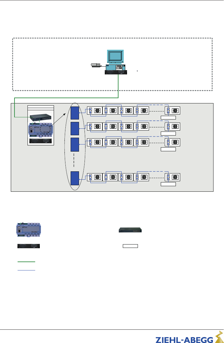
7 Network overview
Example:
Matrix printer
Monitoring
FFU Monitoring System – ZA
UPS
Control
Room
Panel
Ethernet
Master Gateway (19" withdrawable unit)
connection max. 567 FFU´s
9 channel
UPS (19" withdrawable unit)
Uninterruptible Power Supply
600VA & USV
Ethernet Switch 10/100Base (19" withdrawable unit)
16xTX (unmanaged)
Modbus RTU RS485 CAT5 (STP) max. 500m
Ethernet Standard CAT5 max. 100m
3
1
2
9 Modbus channels
per Gateway
150 Ohm
Max 63 FFU
150 Ohm
Max 63 FFU
150 Ohm
Max 63 FFU
9
150 Ohm
Max 63 FFU
max 9 x 63 FFU per Gateway = 567 FFU
We recommend not to use more than 50 devices per channel, to have additional
space for future extensions
150 Ohm
Termination 150 Ohm
Operating Instructions NETcon – model series DIG-9NE Network overview
L-BAL-E134-GB 2105 Index 002 Part.-No.
19/22

8 Enclosure
8.1 Technical data
Voltage supply 24 V DC +/- 10 % 400 mA (Phoenix 2 pole / Lumberg plug)
Interfaces
•
Ethernet
– 1 x LAN (RJ-45 Terminal, shielded with integrated
LEDs)
– 10/100BaseT Ethernet
•
MODBUS RTU RS485
– 9 x RS-485 (RJ-45 Terminal, unshielded)
– COM Parameter: 19,2kBd, 8E1
– Galvanic isolation between all channels (Uiso
1000Vrms)
– Integrated network and fail safe termination (150 Ω)
– 9 x Traffic LEDs (green)
– 1 x Operation LED (orange)
– up to 63 ECblue fans per channel
Max. permissible ambient temper-
ature
40 °C
Permissible rel. humidity 85 % no condensation
Electromagnetic compatibility for
the standard voltage 230 / 400 V
according to DIN IEC 60038
Interference emission EN 61000-6-3 (domestic household ap-
plications)
Interference immunity EN 61000-6-2 (industrial applications)
Housing protection IP20
Weight 0,2 kg
Operating Instructions NETcon – model series DIG-9NE Enclosure
L-BAL-E134-GB 2105 Index 002 Part.-No.
20/22

8.2 Connection diagram
EAUN14K0
01.02.2011
NETcon*
V+
in
V-
in
V-
in
V+
in
-
+
Spannungsversorgung
Power supply
24 V DC
RJ45
LAN USB
RJ45
RJ45RJ45
RJ45
RJ45RJ45
ohne Funktion
without function
Ch1 Ch2 Ch3 Ch4
Ch5Ch6Ch7Ch8Ch9
RJ45
RJ45
RJ45
*DIG-9NE
1
2
3
1 Connection Supply voltage
2 RS-485 channel
3 Ethernet connection
8.3 Dimensions [mm]
Operating Instructions NETcon – model series DIG-9NE Enclosure
L-BAL-E134-GB 2105 Index 002 Part.-No.
21/22

8.4 Manufacturer reference
Our products are manufactured in accordance with the relevant international regulations.
If you have any questions concerning the use of our products or plan special uses,
please contact:
ZIEHL-ABEGG SE
Heinz-Ziehl-Straße
74653 Künzelsau
phone: +49 (0) 7940 16-0
info@ziehl-abegg.de
http://www.ziehl-abegg.com
8.5 Service information
If you have any technical questions while commissioning or regarding malfunctions,
please contact our technical support for control systems - ventilation technology.
phone: +49 (0) 7940 16-800
Email: fan-controls-service@ziehl-abegg.de
Our worldwide contacts are available in our subsidiaries for deliveries outside of Ger-
many, see www.ziehl-abegg.com.
Operating Instructions NETcon – model series DIG-9NE Enclosure
L-BAL-E134-GB 2105 Index 002 Part.-No.
22/22
