1
Using other Vernier data-collection apps or want to connect via
USB?
Visit www.vernier.com/start-go-direct
Note: This sensor also works with LabQuest 2 and LabQuest 3; it does not work
with the original LabQuest.
Charging the Sensor
Connect Go Direct Energy to the included USB Charging Cable and any USB
device for two hours.
You can also charge up to Go Direct Energy Sensors using our Go Direct Charge
Station, sold separately (order code: GDX-CRG). An LED on each
GoDirectEnergy indicates charging status.
Charging
Orange LED next to the battery icon is solid while
the sensor is charging.
Fully charged
Green LED next to the battery icon is solid when
the sensor is fully charged.
Powering the Sensor
Turning on the sensor
Press the Power button once. Red LED indicator
next to the Bluetooth icon flashes when the unit is
on.
Putting the sensor in
sleep mode
Press and hold the Power button for more than
three seconds to put into sleep mode. Red LED
indicator next to Bluetooth icon stops flashing
when sleeping.
Connecting the Sensor
See the following link for up-to-date connection information:
www.vernier.com/start/gdx-nrg
Connecting via Bluetooth
Ready to connect Red LED next to the Bluetooth icon flashes when
sensor is awake and ready to connect.
Connected Green LED next to the Bluetooth icon flashes
when sensor is connected via Bluetooth.
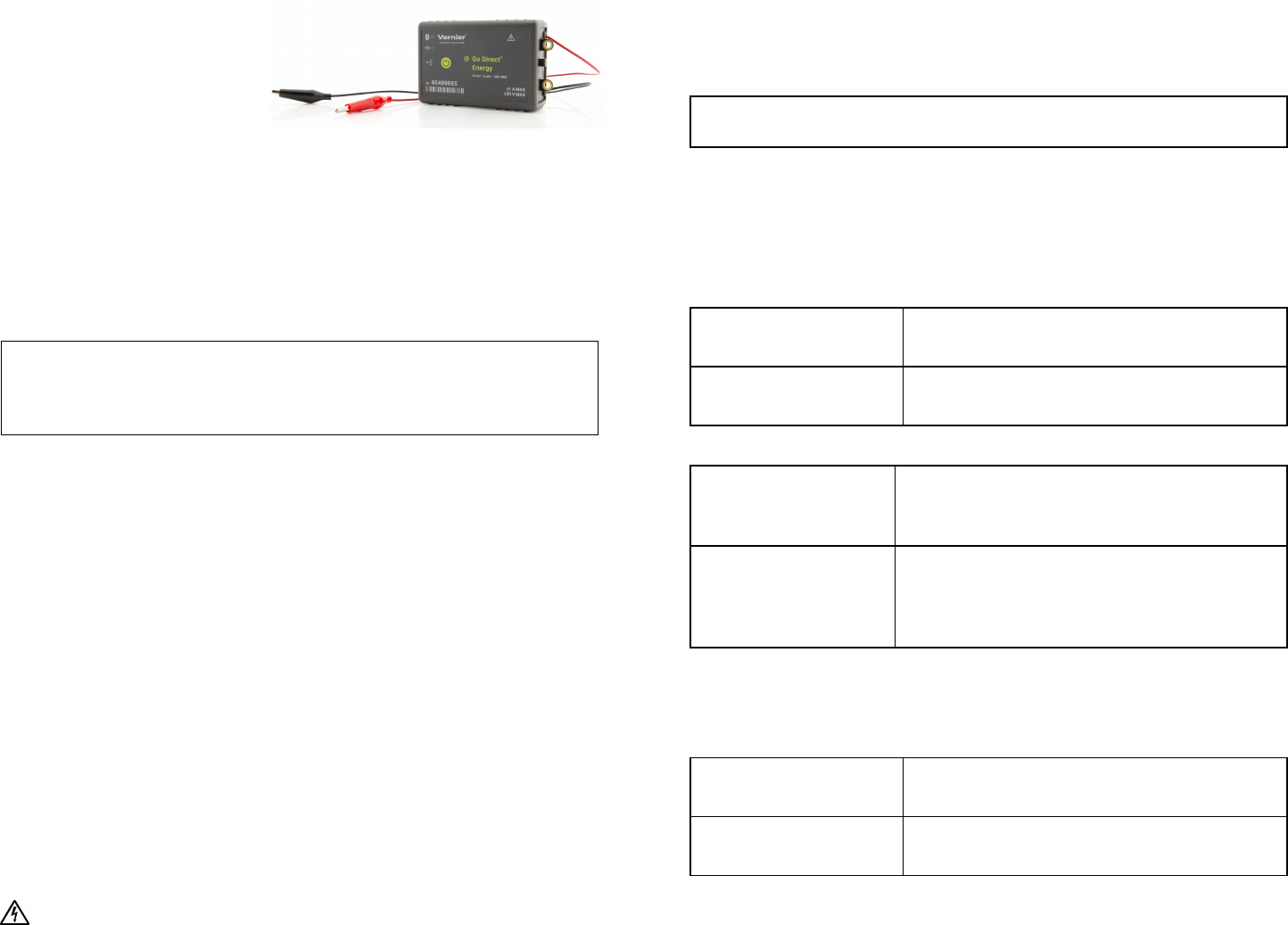
Go Direct
®
Energy
(Order Code GDX-NRG)
Go Direct Energy measures the
voltage and current of a renewable
energy source. Connect a source, such as a small wind turbine or solar panel, and
Graphical Analysis 4 calculates the power, resistance, and energy output.
Go Direct Energy is ideal for a wide variety of renewable energy experiments:
l
Investigate the electrical energy generated by a wind turbine or solar panel.
l
Explore the effect of load on wind turbine or solar panel output.
l
Test blade design variables and evaluate data to determine optimal blade
design.
Note: Vernier products are designed for educational use. Our products are not
designed nor are they recommended for any industrial, medical, or commercial
process such as life support, patient diagnosis, control of a manufacturing
process, or industrial testing of any kind.
What's Included
l
Go Direct Energy
l
Micro USBCable
Compatible Software
See www.vernier.com/manuals/gdx-nrg for a list of software compatible with
GoDirectEnergy.
Quick Start: Vernier Graphical Analysis
®
and Bluetooth
®
1. Connect the Go Direct Energy red lead to the red wire of your energy source
(generator, solar panel, etc.).
2. Connect the Go Direct Energy black lead to the black wire of your source.
3. Make sure the Load switch is set to Internal 30 Ω Load.
4. Charge your sensor for at least 2 hours before first use.
5. Turn on your sensor. The LED will blink red.
6. Launch Graphical Analysis, then click Sensor Data Collection.
7. Select your sensor from the list. The sensor ID is located on the sensor label
near the bar code. Note: If you don’t see a list of available sensors, click
WIRELESS. After selecting your sensor, click Pair.
8. This is a multi-channel sensor. Click SENSORCHANNELS and select the
channel(s) you want to use.
9. Click DONE. You are now ready to collect data.
WARNING: To avoid possible electric shock or personal injury, do not
connect the red or black leads to household power. This product is designed to
measure low-voltage sources such as classroom-scale wind turbines and small
solar panels. It should never be connected to an electrical outlet.

2
power is generated or used over a period of time. This sensor uses units of joules,
abbreviated J, to measure energy.
Current
Current is the measure of the flow of electrons through the wires. When the
current is high, the electrons flow quickly through a circuit. When the current is
low, the electrons flow more slowly. This sensor uses units of milliamperes, often
called milliamps for short. The symbol used to represent milliamps is mA.
Potential
To make the electrons move through the wire, they need to be "pushed." The
amount of push is called the potential difference. Potential difference is measured
in units of volts. The letter V is used to represent a volt.
Power
Power is the measure of how quickly energy is generated or used. This sensor uses
units of milliwatts, abbreviated mW, to measure power.
Resistance
Resistance is a measure of the amount of opposition to the passage of an electric
current. The unit for resistance is ohm and is represented by the Greek letter
capital omega, Ω.
Using the Load Switch
When the Load switch is set to Internal, the load is an internal 30 Ω resistor inside
the Energy sensor. When the Load switch is set to External Load, you will need to
connect an external load. For example, in several experiments students explore the
effect of load on energy output.
Videos
View videos related to this product at www.vernier.com/gdx-nrg
Calibrating the Sensor
The sensor is factory calibrated. You should never have to perform a new
calibration for Go Direct Energy.
Connecting via USB
Connected and charging Orange LED next to the battery icon is solid when
the sensor is connected to Graphical Analysis via
USB and the unit is charging. LED next to
Bluetooth icon is off.
Connected, fully charged Green LED next to the battery icon is solid when
the sensor is connected to Graphical Analysis via
USB and fully charged. LED next to Bluetooth
icon is off.
Charging via USB,
connected via Bluetooth
Orange LED next to the battery icon is solid when
the sensor is charging. Green LED next to the
Bluetooth icon flashes.
Using the Product
Connect the sensor following the steps in the Quick Start section of the user
manual.
Connecting the Energy Sensor to an Energy Source
The Vernier Energy sensor is designed to measure the output of simple generators
and solar panels, such as the KidWind renewable energy kits. Connect the red clip
lead on the sensor to the positive (red) side of the energy source and the black clip
lead to the negative (black) side of the energy source. In the most common
configuration, the Load switch should be set to Internal30Ω Load.
To use an external load, such as a pump, lights, buzzers, etc., set the Load switch
to External Load.
The Check Load LED, , will flash when Go Direct Energy detects that there is
a potential between the red and black leads, but no load is connected. If you do not
have an external load connected, make sure the Load switch is set to Internal 30 Ω
Load. Using Go Direct Energy with this LED flashing will result in measurements
of potential, but since no current flows, there will be no other quantities measured.
Channels
Go Direct Energy records data in five measurement channels:
l
Potential (V)
l
Current (mA)
l
Power (mW)
l
Resistance (Ω)
l
Energy (J)
Energy
If your goal is to simply compare the total amount of electrical energy produced in
a given time, such as in the KidWind Challenge, the most common number to use
is the final value of the Energy column. Energy is the measure of how much total

3
How the Sensor Works
Go Direct Energy measures the potential across the load, as well as the current
through the load. The power, energy, and resistance values are all calculated from
the potential and current.
Does the sensor need to be grounded?
No, Go Direct Energy does not need to be grounded. However, be aware that the
black lead is common to the USB ground, so if you are using Go Direct Energy
connected to USB, the ground of your USB device is the same as the circuit
ground.
Connecting an External Load to the Energy Sensor
You can connect an external load such as any electrical device that is meant to run
on DC electricity at a voltage that matches the power source. Examples include
the Vernier Variable Load (order code VES-VL), the Vernier Resistor Board
(order code VES-RB), single component resistors, motors, pumps, or LEDs. The
metal-coated holes are designed to accommodate alligator clip connectors.
Self-resetting Fuse
The circuit in Go Direct Energy includes a self-resetting fuse to protect the
components from accidental overloading. Currents over 1 A (external load) or
0.18A (internal load) may cause the fuse to open the circuit. In this case, you will
have to wait a few minutes for the fuse to reset itself before using
GoDirectEnergy again.
Can I use this as a Current Sensor or a Voltage Sensor?
Although Go Direct Energy can be used to measure simple circuits in a physics
classroom, it is designed primarily for use with simple motors and solar panels.
We recommend the Go Direct Voltage and Go Direct Current sensors for doing
battery-and-bulb type experiments, as the addition of a load is not necessary when
using those sensors.
Specifications
Source input potential
range
±5 V (for internal load)
±30 V (for external load)
Source input current range ±0.18 A (for internal load)
±1 A (for external load)
Resolution 1 mV
40 µA
Input impedance 1 MΩ
Insertion resistance 1 Ω
Wireless specification Bluetooth 4.2
Maximum wireless range 30 m
Battery 300 mA Li-Poly
Battery life (single full
charge)
~24 hours
Battery life (long term) ~500 full charge cycles (several years depending on
usage)
Care and Maintenance
Battery Information
Go Direct Energy contains a small lithium-ion battery. The system is designed to
consume very little power and not put heavy demands on the battery. Although the
battery is warranted for one year, the expected battery life should be several years.
Replacement batteries are available from Vernier (ordercode:GDX-BAT-300).
Storage and Maintenance
To store Go Direct Energy for extended periods of time, put the device in sleep
mode by holding the button down for at least three seconds. The red LED will
stop flashing to show that the unit is in sleep mode. Over several months, the
battery will discharge but will not be damaged. After such storage, charge the
device for a few hours, and the unit will be ready to go.
Exposing the battery to temperatures over 35°C (95°F) will reduce its lifespan. If
possible, store the device in an area that is not exposed to temperature extremes.
Water Resistance
Go Direct Energy is not water resistant and should never be immersed in water. If
water gets into the device, immediately power the unit down (press and hold the
power button for more than three seconds). Disconnect the sensor and charging
cable, and remove the battery. Allow the device to dry thoroughly before
attempting to use the device again. Do not attempt to dry using an external heat
source.
4
Warranty
Warranty information for this product can be found on the Support tab at
www.vernier.com/gdx-nrg
General warranty information can be found at www.vernier.com/warranty
Disposal
When disposing of this electronic product, do not treat it as household waste. Its
disposal is subject to regulations that vary by country and region. This item should
be given to an applicable collection point for the recycling of electrical and
electronic equipment. By ensuring that this product is disposed of correctly, you
help prevent potential negative consequences on human health or on the
environment. The recycling of materials will help to conserve natural resources.
For more detailed information about recycling this product, contact your local city
office or your disposal service.
Battery recycling information is available at www.call2recycle.org
Do not puncture or expose the battery to excessive heat or flame.
The symbol, shown here, indicates that this product must not be disposed of in
a standard waste container.
Federal Communication Commission Interference Statement
This equipment has been tested and found to comply with the limits for a Class B digital device, pursuant to Part 15 of the FCC rules. These
limits are designed to provide reasonable protection against harmful interference in a residential installation. This equipment generates,
uses and can radiate radio frequency energy and, if not installed and used in accordance with the instructions, may cause harmful
interference to radio communications. However, there is no guarantee that interference will not occur in a particular installation. If this
equipment does cause harmful interference to radio or television reception, which can be determined by turning the equipment off and on,
the user is encouraged to try to correct the interference by one or more of the following measures:
Reorient or relocate the receiving antenna.
Increase the separation between the equipment and receiver.
Connect the equipment into an outlet on a circuit different from that to which the receiver is connected.
Consult the dealer or an experienced radio/TV technician for help.
FCC Caution
This device complies with Part 15 of the FCC Rules. Operation is subject to the following two conditions:
(1) this device may not cause harmful interference and
(2) this device must accept any interference received, including interference that may cause undesired operation
RF Exposure Warning
The equipment complies with RF exposure limits set forth for an uncontrolled environment. The antenna(s) used for this transmitter must not
be co-located or operating in conjunction with any other antenna or transmitter. You are cautioned that changes or modifications not
expressly approved by the party responsible for compliance could void your authority to operate the equipment.
IC Statement
This device complies with Industry Canada license-exempt RSS standard(s). Operation is subject to the following two conditions:
(1) this device may not cause interference, and
(2) this device must accept any interference, including interference that may cause undesired operation of the device.
Industry Canada - Class B This digital apparatus does not exceed the Class B limits for radio noise emissions from digital apparatus as set
out in the interference-causing equipment standard entitled “Digital Apparatus,” ICES-003 of Industry Canada. Operation is subject to the
following two conditions: (1) this device may not cause interference, and
(2) this device must accept any interference, including interference that may cause undesired operation of the device.
To reduce potential radio interference to other users, the antenna type and its gain should be so chosen that the equivalent isotropically
radiated power (e.i.r.p.) is not more than that permitted for successful communication.
RF exposure warning: The equipment complies with RF exposure limits set forth for an uncontrolled environment. The antenna(s) used for
this transmitter must not be co-located or operating in conjunction with any other antenna or transmitter.
Troubleshooting
The Check Load LED, , will flash when Go Direct Energy detects that there is
a potential between the red and black leads, but no load is connected. If you do not
have an external load connected, make sure the Load switch is set to Internal 30 Ω
Load. Using Go Direct Energy with this LED flashing will result in measurements
of potential, but since no current flows, no other quantities will be measured.
Resistance Values Fluctuate
When the current and voltage values are near zero, the resistance value is not
meaningful; it may fluctuate widely.
Thermal Protection
Go Direct Energy uses internal thermal fuses to protect the sensor from
overheating. For the Internal Load, if the potential increases above 5.5 V, the
thermal fuse will start to engage and internal resistance will begin to increase.
Over approximately 7.7 V, the thermal fuse will fully engage, meaning that the
sensor is overheated and all readings will go to zero. If this happens, disconnect all
wires and allow the sensor to cool for 10 minutes before starting another
measurement.
When using the External Load, the thermal fuse will start to engage if the current
increases above 1.1 A. Continued operation above this point will cause the thermal
fuse to fully engage, meaning that the sensor is overheated and all readings will go
to zero.
For additional troubleshooting and FAQs, see www.vernier.com/til/4123
Repair Information
If you have followed the troubleshooting steps and are still having trouble with
your Go Direct Energy, contact Vernier Technical Support at
you to determine if the unit needs to be sent in for repair. At that time, a Return
Merchandise Authorization (RMA) number will be issued and instructions will be
communicated on how to return the unit for repair.
Accessories/Replacements
Item Order Code
Micro USB Cable
CB-USB-MICRO
USB-C to Micro USBCable
CB-USB-C-MICRO
Go Direct 300 mAh Replacement Battery
GDX-BAT-300
Vernier Variable Load
VES-VL
Vernier Resistor Board
VES-RB
KidWind Advanced Wind Experiment Kit
KW-AWX
KidWind Basic Wind Experiment Kit
KW-BWX
KidWind MINI Wind Turbine
KW-MWT
KidWind 2V/400mA Solar Panel
KW-SP2V

5
Vernier Science Education
13979 SW Millikan Way • Beaverton, OR 97005-2886
Toll Free (888) 837-6437 • (503) 277-2299 • Fax (503) 277-2440
Rev. 6/27/2024
Go Direct, Vernier Graphical Analysis, LabQuest, and other marks shown are our trademarks or registered trademarks
in the United States. All other marks not owned by us that appear herein are the property of their respective owners,
who may or may not be affiliated with, connected to, or sponsored by us.
The Bluetooth
®
word mark and logos are registered trademarks owned by the Bluetooth SIG, Inc. and any use of such
marks by Vernier Science Education is under license. Other trademarks and trade names are those of their respective
owners.
Le présent appareil est conforme aux CNR d’Industrie Canada applicables aux appareils radio exempts de licence. L’exploitation est
autorisée aux deux conditions suivantes :
(1) l’appareil ne doit pas produire de brouillage, et
(2) l’appareil doit accepter tout interférence radioélectrique, même si cela résulte à un brouillage susceptible d’en compromettre le
fonctionnement.
Cet appareil numérique respecte les limites de bruits radioélectriques applicables aux appareils numériques de Classe B prescrites dans la
norme sur le matériel interférant-brouilleur: “Appareils Numériques,” NMB-003 édictée par industrie Canada. L’utilisation est soumise aux
deux conditions suivantes:
(1) cet appareil ne peut causer d’interférences, et
(2) cet appareil doit accepter toutes interférences, y comprises celles susceptibles de provoquer un disfonctionnement du dispositif.
Afin de réduire les interférences radio potentielles pour les autres utilisateurs, le type d’antenne et son gain doivent être choisie de telle
façon que l’équivalent de puissance isotrope émis (e.i.r.p) n’est pas plus grand que celui permis pour une communication établie.
Avertissement d’exposition RF: L’équipement est conforme aux limites d’exposition aux RF établies pour un environnement non
supervisé. L’antenne (s) utilisée pour ce transmetteur ne doit pas être jumelés ou fonctionner en conjonction avec toute autre antenne ou
transmetteur.
Note: This product is a sensitive measurement device. For best results, use the cables that were provided. Keep the device away from
electromagnetic noise sources, such as microwaves, monitors, electric motors, and appliances.
