
Wireless Drive-Thru Audio System
Operating Instructions
HME# 400G699 Rev B 2/19/15
HM Electronics, Inc.
14110 Stowe Drive
Poway, CA 92064 USA
Phone: 800-848-4468
Fax: 858-552-0172
Website: www.hme.com
Email: [email protected]

Table of Contents
EOS|HD EQUIPMENT ........................................................................................................................................................ 1
Base Station ................................................................................................................................................................................. 2
Base Station Display Screen ................................................................................................................................................... 3
Headsets ...................................................................................................................................................................................... 4
Features and Controls ............................................................................................................................................................. 4
How to Wear the Headset ....................................................................................................................................................... 4
How to Use the Headset Controls ........................................................................................................................................... 5
Headset Registration ............................................................................................................................................................... 5
Battery Removal and Replacement......................................................................................................................................... 8
Battery Charger ........................................................................................................................................................................... 9
EOS|HD OPERATION ...................................................................................................................................................... 10
Changing Language of Headset Cues ........................................................................................................................................ 10
Obtaining Headset Status ........................................................................................................................................................... 10
Single-Lane Operation ............................................................................................................................................................... 11
Multiple-Lane Operation ........................................................................................................................................................... 12
Tandem Operation ..................................................................................................................................................................... 13
Internal Communication ............................................................................................................................................................ 13
Speed-Team Operation Mode .................................................................................................................................................... 14
Message Center Operation ......................................................................................................................................................... 15
Customer Greeter Settings .................................................................................................................................................... 17
Reminder Message Settings .................................................................................................................................................. 21
Alert Message Settings ......................................................................................................................................................... 26
Schedule Times ......................................................................................................................................................................... 33
Volume Adjustments ................................................................................................................................................................. 34
In/Out-bound Audio Volume ................................................................................................................................................ 34
Ceiling Speaker Volume ....................................................................................................................................................... 37
Line In/Out ........................................................................................................................................................................... 37
Vehicle Tone in Headset ...................................................................................................................................................... 37
Wired Backup System Operation .............................................................................................................................................. 38
Vehicle Detection ...................................................................................................................................................................... 39
Store Settings ............................................................................................................................................................................. 40
Network Settings ....................................................................................................................................................................... 48
Basic Network Settings ........................................................................................................................................................ 48
Advanced Network Settings ................................................................................................................................................. 50
Email/Texting ....................................................................................................................................................................... 53
PC Navigation ........................................................................................................................................................................... 56
EQUIPMENT CARE AND CLEANING ......................................................................................................................... 58
Handling the Equipment Properly ............................................................................................................................................. 58
Cleaning the Equipment ............................................................................................................................................................ 58
IN CASE OF PROBLEMS ................................................................................................................................................ 59
Troubleshooting ......................................................................................................................................................................... 59
Service Call ............................................................................................................................................................................... 60
Base Station Internal Connectors and Controls ......................................................................................................................... 61
Diagnostics ................................................................................................................................................................................ 62
EQUIPMENT SPECIFICATIONS ................................................................................................................................... 63
IMPORTANT NOTICES ................................................................................................................................................... 64
APPENDIX .......................................................................................................................................................................... 64
Multiple-Lane Operation ........................................................................................................................................................... 66
Dedicated Mode ................................................................................................................................................................... 66
Multiple-Lane Message Center Settings .................................................................................................................................... 67
Customer Greeter Messages ................................................................................................................................................. 67
Reminder Messages .............................................................................................................................................................. 67
Alert Messages ..................................................................................................................................................................... 67
Access Control of EOS|HD Menus............................................................................................................................................ 68
Figures and Diagrams
Figure 1. Standard equipment ........................................................................................................................................................ 1
Figure 2. Base station front panel features ..................................................................................................................................... 2
Figure 3. Headset controls ............................................................................................................................................................. 4
Figure 4. Correct wearing of the headset ....................................................................................................................................... 4
Figure 5. Headset battery-release button ........................................................................................................................................ 8
Figure 6. Batteries in charger ......................................................................................................................................................... 9
Figure 7. Typical tandem drive-thru ............................................................................................................................................ 13
Figure 8. Wired backup switches on bottom of base station ........................................................................................................ 38
Figure 9. Base station internal connectors and controls ............................................................................................................... 61
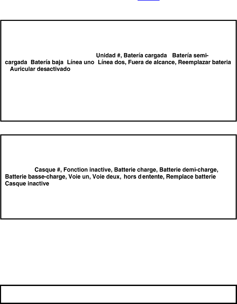
The Headset provides basic operating cues in Spanish and French, as follows. Refer
also to the Changing Languages instructions on page 10.
© 2015 HM Electronics, Inc.
The HME logo and product names are registered trademarks of HM Electronics, Inc. All rights reserved.
US Patent 7,920,539 B2
Español
El auricular proporciona información que indica el estado del funcionamiento
del mismo en español como es: ,
, , ,
y .
Para cambiar el idioma de la información que se escucha en el auricular de inglés
a español, siga los siguientes pasos: - Oprima y mantenga presionado el botón
“A1” y al botón para bajar el volumen “V” y el botón para encender el auricular
al mismo tiempo, hasta que el auricular se encienda.
Français
Le casque fournit les sélections de fonctionnement fondamentales suivantes en
français:
et
.
Pour changer les indications de l'anglais au français, appuyer et tenir le “A1” et le
volume en bas “V” en même temps, tout en appuyant sur le boutton d’allumage.
Illustrations in this publication are approximate representations of
the actual equipment, and may not be exactly as the equipment appears.
HM Electronics, Inc. is not responsible for equipment malfunctions due to erroneous translation of
its installation and / or operating publications from their original English versions.

Important Safety and Usage Information
CAUTION:
As would be the case with any audio device, such as headphones or a headset,
that carries amplified sound to the ears, misuse of such a device or use at excessive volume
levels may cause hearing impairment or loss of hearing. The following safety instructions must
be followed when using the all-in-one headset transceiver. Failure to follow these safety
instructions could result in injury.
Avoiding Hearing Damage: Permanent hearing loss may occur if the all-in-one headset
transceiver is used at excessive volume levels. Turn on the all-in-one headset and check the
volume prior to use. The audio volume may be adjusted by using the up / down arrow buttons
on the all-in-one headset.
Prolonged use at excessive volume levels over time may sound normal but can be damaging to
hearing. If you experience ringing in the ears or muffled speech sounds, discontinue use and
have your hearing checked. The louder the volume, the less time is required before your
hearing could be affected.
The following precautions should be taken to protect your hearing:
Limit the amount of time you use the all-in-one headset at high volume.
Avoid turning up the volume to block out noisy surroundings.
Turn the volume down if you can’t hear people speaking near you.

1
EOS|HD EQUIPMENT
The EOS|HD is an audio system primarily for use at quick-
service restaurants. The equipment shown below is standard
with the EOS|HD. Optional equipment can be ordered from your
local dealer.
Figure 1. Standard equipment
NOTE:
Equipment
quantities vary,
depending on
individual store
needs at time of
purchase.
Additional
equipment can be
ordered from the
list below.
OPTIONAL EQUIPMENT
Equipment Model Number
Headset HS6200
Battery for Headset BAT51
Headset Earmuff None
Headset Earpiece Cover (disposable) None
Telephone Interface TI6000
Vehicle Detector Board VDB102
Vehicle Detector Board (with relay) VDB102R
Vehicle Detector Loop (underground) VDL100
Ceiling Speaker MM100
Microphone DM5
Mode Switch (dual lane) MS10
Remote Speed Team Switch SW2
Switcher Circuit Board None
Antenna Coverage Extension Kit EC10
Extended Coverage Antenna Kit EC20
Remote Antenna Kit
(with 6 ft / 1.83 meter cable) ANT20-6
Remote Antenna Kit
(with 30 ft / 9.14 meter cable) ANT20-30

2
Display
screen
Menu-select
buttons
Help button
Back button
Activity
indicators
Reset switch
(recessed)
Cabinet latches
(not shown)
Base Station
All functions of the drive-thru audio system are channeled through the base
station. It is the electronic heart of the EOS|HD. External base station features
are shown in Figure 2. Internal connectors and controls are shown in Figure 10.
The menu-select buttons are used to make selections from the menu on the
display screen.
The Help button can be pushed to obtain information needed in case of problems
with the EOS|HD.
The Back button can be pushed to go back to the previous menu display, saving
any setting changes or exiting a display screen when no changes have been made.
The activity indicators light up as follows:
Above the line - Lane 1 activity (single or multiple-lane operations)
A1 lights up when the A button is pushed on any headset in single-lane
operations, or on any Lane 1 headset in multiple-lane operations.
B1 lights up when the B button is pushed on any headset in single-lane
operations, or on any Lane 1 headset in multiple-lane operations.
The car above the line lights up when a car is present at the menu board in
single-lane operations, or at the Lane 1 menu board in multiple-lane operations.
Below the line - Lane 2 activity (multiple-lane operations only)
A2 lights up when the A button is pushed on any Lane 2 headset.
B2 lights up when the B button is pushed on any Lane 2 headset.
The car below the line lights up when a car is present at the Lane 2 menu board.
When both of the cabinet latches, on top of the cabinet are pressed down at the
same time, the cabinet can be opened by pulling forward and down.
The reset switch is used to perform a soft restart of the base station. It is located
in a small hole on the right side of the base station. To press the reset switch,
carefully push a small pointed object, such as an unfolded paper clip, into the hole.
Figure 2. Base station front panel features
3
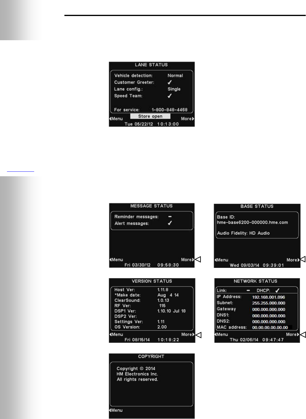
Base Station Display Screen
The display screen is where all menu selections will be seen for
installer setups and routine operation options.
The display screen will turn off (sleep) if there is no button
activity. Pressing any button will turn it back on (wake it up).
Press the Menu button at the bottom-left of the LANE STATUS
display to view the MAIN MENU, which provides access to system
settings. Press the More button on the MAIN MENU for
additional settings.
Press the More button at the bottom-right of the LANE STATUS
display to view additional system status, and then press the More
button at the bottom-right of any other STATUS display. The
information on each STATUS display shows other base station
information needed to operate the system on a network and to
identify its version data.
NOTE:
These instructions
and the display screens
shown are primarily for
single-lane drive-thru
operations.
In multiple-lane operations,
the LANE STATUS display
shows Vehicle detection for
L1 (Lane 1) and L2 (Lane 2),
and Lane Config shows the
lane configuration setting.
The Dedicated mode
✔
(on)
or
−
(off) setting is also
shown. For multiple-lane
operations, where additional
displays require explanation,
you will be directed to the
Appendix.
The LANE STATUS display will be
shown on the base station until
either the Menu or More button is
pushed.

4
Headsets
Features and Controls
How to Wear the Headset
Wear the headset with the microphone on your right or left side
next to your mouth.
Adjust the headband and microphone boom as needed.
Figure 3. Headset controls
Figure 4. Correct wearing of the headset
Transmit
light
Channel “A1”
button
Channel “A2”
button
Channel “B”
button
Volume-up
button
Volume-down
button
Power
light
Power
button
Hold microphone
boom here to adjust
microphone
position

5
How to Use the Headset Controls
The control buttons will activate when pressed firmly. Use your
fingertips, not your fingernails, to press the buttons.
Power On/Off
Power On Press and release the power button.
A voice message in the headset will say “headset #, battery
full/half/low” and both the power light and the transmit light will
flash red. After a short time, the power light will change to steady
green for Lane 1 and the transmit light will go off. A voice message in
the earpiece will then say “Lane 1 (or 2).”
Power Off — Press and hold the power button for about two
seconds. A voice message in the earpiece will say “headset off,” and
the power light will go off.
Volume Up/Down
Volume-Up Adjustment — Press and release the volume-up Λ
button. Each time you press the button you will hear a higher pitch
beep in the earpiece as the volume increases. When you reach
maximum volume, you will hear a high-pitched double beep. If you
press and hold the volume-up Λ button, you will hear repeating
beeps, increasing in pitch until the volume reaches maximum.
Then you will hear high-pitched double beeps repeating until you
release the volume-up Λ button.
Volume-Down Adjustment — Press and release the volume-
down V button. Each time you press the button you will hear a
lower pitch beep in the earpiece as the volume decreases. When
you reach minimum volume, you will hear a low-pitched double
beep. If you press and hold the volume-down V button, you will
hear repeating beeps, decreasing in pitch until the volume
reaches minimum. Then you will hear low-pitched double beeps
repeating until you release the volume-down V button.
Headset Registration
During installation of the EOS|HD, each headset was registered
for use with the base station. The base station recognizes all
headsets registered to it when their power is on, and will be able
to tell the difference between them and other electronic
equipment operating on similar frequencies.
A maximum of 15 headsets can be registered. If one is replaced,
you must register the new one before you use it. When a headset
is replaced, the old one remains in memory.
If the maximum number of 15 (in memory) is exceeded, the base
station HEADSET REGISTRATION display will tell you that 0 more
can be registered. If this happens, you may either clear all inactive
headsets (not currently turned on) or clear all registered headsets.
If you clear all inactive headsets, you can initiate the new
registration. Each headset is registered the same way, one at a
time.
NOTE:
All registered headsets
must be turned on, or they
will be unregistered when
you clear inactive headsets.
If you clear all registrations,
you must re-register all
headsets.
6
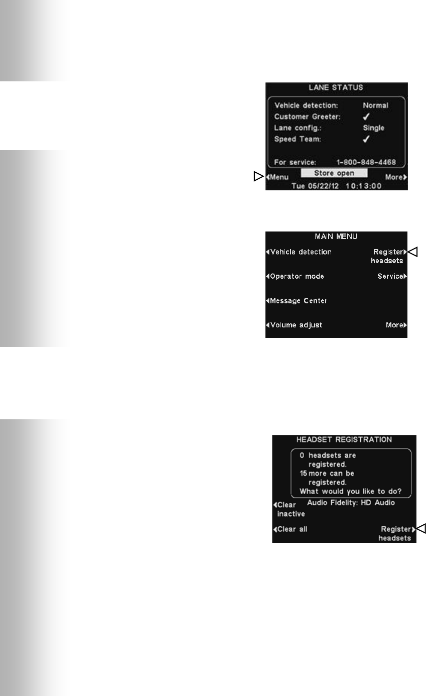
Register each headset as follows:
Be certain all headsets to be registered are turned off and the
base station power is on. Others can be on or off.
On the base station LANE STATUS display, press the Menu
button.
On the MAIN MENU, press the Register headsets button.
On the HEADSET REGISTRATION display, if you press the Clear
inactive button, you will unregister only those headsets that are
turned off.
If you press the Clear all button, you will unregister all headsets
that are registered to the base station, and the base station will
automatically restart.
To register headsets, press the Register headsets button on the
HEADSET REGISTRATION display.
NOTE:
Headsets must be within
6 feet (1.83 meters)
of the base station while
being registered.
NOTE:
You will be given a
warning and allowed to
quit or continue before
registrations are cleared.
7
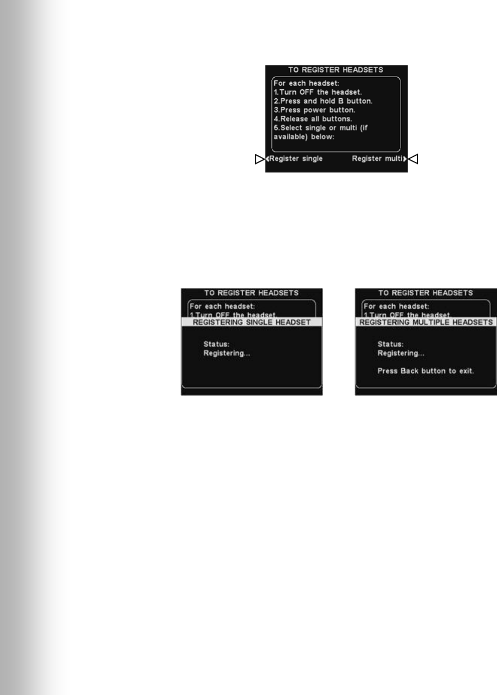
On the TO REGISTER HEADSETS display, follow the
instructions in the box.
If you are registering only one headset, press the Register single
button.
If you are registering more than one headset, press the Register
multi (multiple) button and continue registering each headset,
one at a time.
When each registration is successfully completed:
The ID number assigned to this headset will be shown.
ID numbers are assigned sequentially as 0 thru 9, A, B, C, D and E.
When you have finished registering headsets, press the Back
button to exit the registration mode. You can continue pressing
the Back button repeatedly until you return to the MAIN MENU
or LANE STATUS display.
The power light on the headset will remain on steady green.
If you have any problems registering headsets:
In the USA, call HME Customer Support at 1-800-848-4468.
Outside the USA, call your local HME representative for assistance.

8
Battery-release
button (blue)
Battery
Battery Removal and Replacement
To change batteries:
When a battery becomes weak, a voice in the headset will say
“Change battery.” When this happens, press the battery-release
button and slide the battery out of the headset as shown in
Figure 5.
To replace batteries:
When replacing a battery in the headset, place the end of the
battery with the metal contacts into the headset, in the same
position as the battery you removed. Press the battery carefully
in until it snaps in place.
Recharge batteries according to the instructions on page 9.
Figure 5.
Headset battery-release button
9
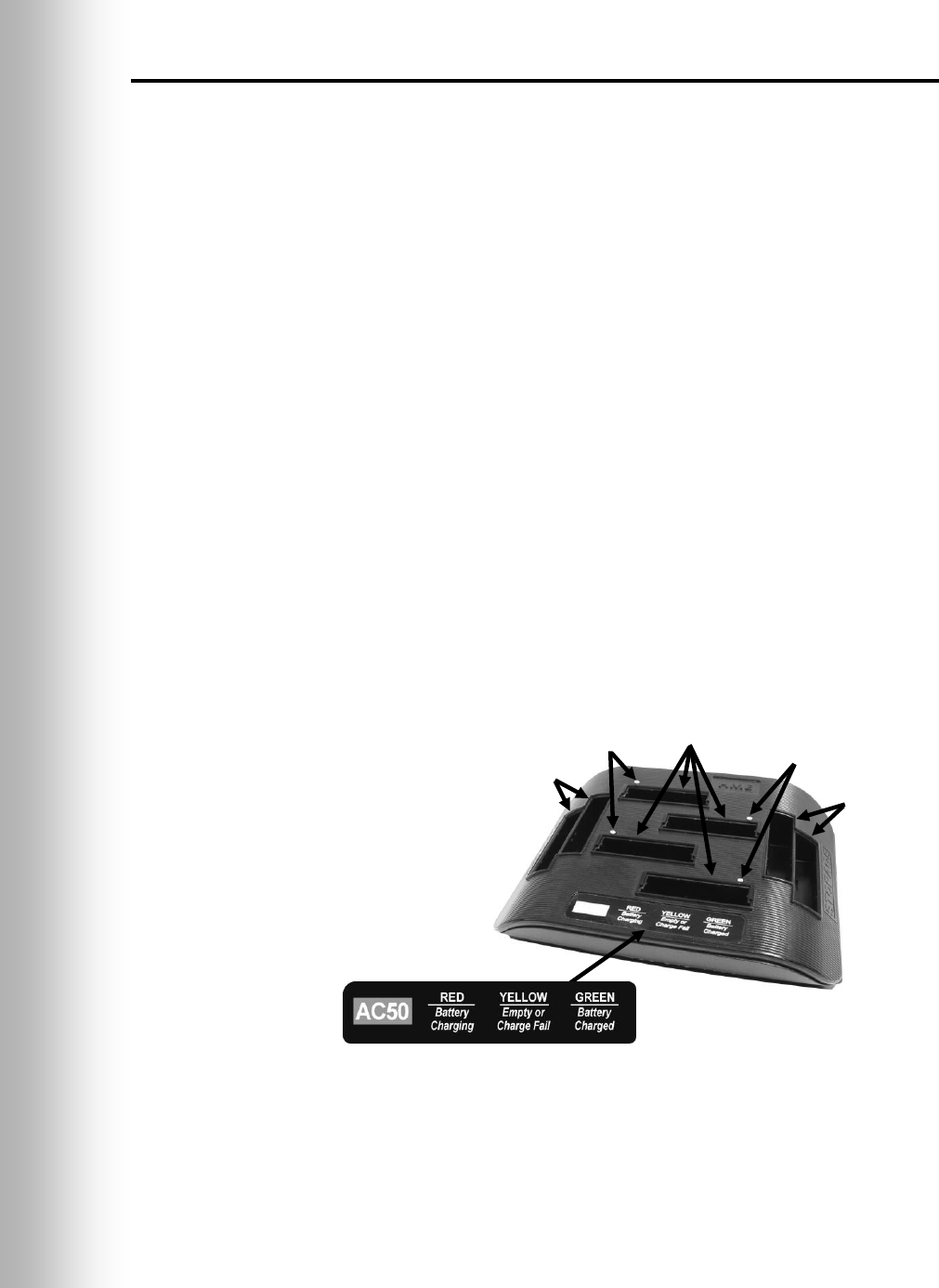
Battery Charger
Up to four batteries can be charged in the charger at the same time.
Charging time is approximately 2.5 hours. The battery status lights
next to each charging port are explained below. Up to six fully
charged batteries can be stored in the battery storage ports.
Procedure:
Insert batteries in the charging ports for charging. The batteries can
only go into the charging ports one way. If they do not go in easily,
turn them around. DO NOT force them. Push each battery down
into a port until it snaps in place, to be sure it makes full contact.
Battery Status Lights:
A yellow light stays on steady next to each charging port while the
port is empty.
Insert a battery in one of the four charging ports until it clicks
in place.
A red light will stay on next to a battery while it is charging.
A green light will go on next to a battery when it is fully charged.
If a yellow light is on next to a battery in a charging port, it
means the charge failed. If this happens: (1) Be sure the battery is
pushed all the way into the port until it snaps into place to make
contact. (2) Try charging in a different port. If it charges this time,
the first charging port may be defective. If the battery does not
charge in the second port, replace it with another battery.
Store up to four fully charged batteries in the storage ports.
Figure 6. Batteries in charger
Battery status
lights
Battery storage
ports
Battery status
lights
Battery storage
ports
Battery
charging
ports

10
EOS|HD OPERATION
The EOS|HD can be operated in Hands-Free (HF), Auto-Hands-Free
(AHF), B-channel Hands-Free (BHF) or Push-To-Talk (PTT) modes.
A full-duplex system supports HF, AHF, BHF and PTT operation. In
HF, AHF and BHF operation, communication can be transmitted
and received at the same time, as in a normal telephone
conversation. In the AHF mode, transmission and reception are
activated automatically when a customer drives into the drive-thru
lane. In the HF mode, transmission and reception are activated by
touching and releasing the A1 or A2 button on the headset. In the
PTT mode, the A1 or A2 button must be pressed and held while the
operator is talking to the customer. A half-duplex system only
supports the PTT mode, and the customer’s voice will not be heard
while the operator is pressing the A1 or A2 button.
In single lane operations, when a customer arrives in the drive-thru
lane, you will hear a single beep in the headset.
In dual-lane operations, when a customer arrives in a drive-thru
lane, you will hear one beep in the headset for Lane 1 and two
beeps for Lane 2.
In dual-lane operation, if you are communicating with a customer in
one lane when another customer arrives in the other lane, you will
hear a beep in the headset. When the customer leaves the speaker
post in the lane you are connected to, the same beep will repeat in
the headset every four seconds until you touch the A1 or A2 button
to communicate with the customer in the other lane.
Refer to the instructions on the following pages for single-lane or
dual-lane stores.
Changing Language of Headset Cues
To change the language of the cues heard in the headset from
English to French to Spanish and back to English, with the
headset power off, press and hold the volume-down V button and
the A1 button while you press the power button. Each time you do
this, the language of the headset cues will change as the power goes
on. When the headset is turned off and on again, the cues will
remain in the last language set.
To change to the next language, with the headset power off, again
press and hold the volume-down V button and the A1 button while
you press the power button.
Obtaining Headset Status
To obtain headset status, with its power off, press and hold the
volume-down V button and the A2 button while you press the
power button. You will hear the status message in the headset
when the power goes on.
NOTE:
In dual-lane operations, if
you have a Mode Switch
and it is set to
“DEDICATED,” you will
only hear beeps in the
headset when a customer
arrives in the lane you
are operating.

11
Single-Lane Operation
Hands-Free (HF) Mode
With the headset power off, press and hold the volume-up Λ and B
buttons while you press and release the power button to turn it on
in the HF mode. The headset will remember this setting.
As a customer enters the drive-thru lane, you will hear an alert
tone (single beep) in your headset, and you will be able to hear the
customer at the speaker post or menu board.
Touch and release the A1 or A2 button to speak and listen to the
customer.
Touch and release the A1, A2 or B button to end communication
with the customer.
Touch and release the A1 or A2 button if you want to speak to the
customer again.
Use the volume-up Λ and down V buttons to adjust the customer’s
voice level in your headset if necessary.
If a customer drives away from the speaker post or menu board, the
headset will stop transmitting.
Auto-Hands-Free (AHF) Mode
With the headset power off, press and hold the volume-up Λ and A1
buttons while you press and release the power button to turn it on
in the AHF mode.
As a customer enters the drive-thru lane, you will hear an alert
tone (single beep) in your headset, and you will be able to hear the
customer at the speaker post or menu board.
Speak and listen to the customer without pressing any buttons.
Touch and release the A1, A2 or B button to end communication
with the customer.
Touch and release the A1 or A2 button if you want to speak to the
customer again.
Use the volume-up Λ and down V buttons to adjust the customer’s
voice level in your headset if necessary.
If a customer drives away from the speaker post or menu board,
the headset will stop transmitting.
B-Channel Hands-Free (BHF) Mode:
With the power off, press and hold the B and A2 buttons while you
press and release the power button to turn the headset on in the
BHF mode.
This will keep the B channel open for hands-free communication
among crew members. If a customer arrives, B-channel
communication will automatically be interrupted to allow
communication with the customer.
Push-To-Talk (PTT) Mode
With the headset power off, press and hold the volume-down V and
B buttons while you press and release the power button to turn it
on in the PTT mode. The headset will remember this setting.
As a customer enters the drive-thru lane, you will hear an alert
tone (single beep) in your headset, and you will be able to hear the
customer at the speaker post or menu board.
Touch and hold the A1 or A2 button to speak to the customer.
Release to stop speaking to the customer (full duplex) or to listen
to the customer (half duplex).
Use the volume-up Λ and down V buttons to adjust the customer’s
voice level in your headset if necessary.
NOTE:
Only one operator at
a time can use the
auto-hands-free
feature, and this
feature must also be
enabled on the base
station.
If a headset is turned
off while in the AHF
mode, it will
automatically be
reset for its previous
operating mode.

12
Multiple-Lane Operation
In a Dual-lane or Y-lane operation, there is one order point per lane.
In a Tandem operation, there are two order points in one lane.
Hands-Free (HF) Mode
With the headset power off, press and hold the volume-up Λ and B
buttons while you press and release the power button to turn it on in
the HF mode. The headset will remember this setting.
As a customer enters a drive-thru lane, you will hear an alert tone
in your headset (single beep for lane 1, double beep for lane 2),
and you will be able to hear the customer at the speaker post or
menu board if that lane is selected.
Touch and release the A1 button for Lane 1 or A2 for Lane 2, to
speak and listen to the customer.
Touch and release the A1, A2 (depending on lane) or B button to
end communication with the customer.
Touch and release the A1 button for Lane 1 or A2 for Lane 2, to
speak to the customer again.
Use the volume-up Λ and down V buttons to adjust the customer’s
voice level in your headset if necessary.
To change lanes, touch and release the opposite A button.
If a customer drives away from the speaker post or menu board,
the headset will stop transmitting.
Auto-Hands-Free (AHF) Mode
For Lane 1 operation, with the headset power off, press and hold
the volume-up Λ and A1 buttons while you press and release the
power button to turn it on in the AHF mode.
For Lane 2 operation, with the headset power off, press and hold
the volume-up Λ and A2 buttons while you press and release the
power button to turn it on in the AHF mode.
As a customer enters a drive-thru lane, you will hear an alert tone
in your headset (single beep for lane 1, double beep for lane 2),
and you will be able to hear the customer at the speaker post or
menu board if that lane is selected.
Speak and listen to the customer without pressing any buttons.
Touch and release the A1, A2 (depending on lane) or B button to
end communication with the customer.
Touch and release the A1 button for Lane 1 or A2 for Lane 2, to
speak to the customer again.
Use the volume-up Λ and down V buttons to adjust the customer’s
voice level in your headset if necessary.
If a customer drives away from the speaker post or menu board,
the headset will stop transmitting.
B-Channel Hands-Free (BHF) Mode:
With the power off, press and hold the B and A2 buttons while you
press and release the power button to turn the headset on in the
BHF mode.
This will keep the B channel open for hands-free communication
among crew members. If a customer arrives, B-channel
communication will automatically be interrupted to allow
communication with the customer.
Push-To-Talk (PTT) Mode
With the headset power off, press and hold the volume-down V and B
buttons while you press and release the power button to turn it on in the
PTT mode. The headset will remember this setting.
NOTE:
In each lane, only one
operator at a time can
use the auto-hands-free
feature. If an operator
attempts to configure a
second headset,
“System busy” will be
heard in his/her
headset.
When operating in the
AHF mode, changing
lanes is not possible.
If a headset is turned off
while in the AHF mode,
it will automatically be
reset for its previous
operating mode.
NOTE:
If you have an optional
MS10 Mode Switch,
placing the switch in the
Non-Dedicated position
allows operators to hear
alert tones when a
customer arrives in
either lane. Placing the
switch in the Dedicated
position allows an
operator for either lane
to hear only alert tones
for customers arriving in
his/her own lane.
If you do not have an
MS10 Mode Switch, use
the base station menus
to change modes. The
OPERATOR MODE
display on the base
station, must have the
dedicated mode set to
Ext to use an MS10.
13
As a customer enters a drive-thru lane, you will hear an alert tone
in your headset (single beep for lane 1, double beep for lane 2),
and you will be able to hear the customer at the speaker post or
menu board if that lane is selected.
Touch and hold the A1 button to speak to a customer in Lane 1, or
A2 to speak to a customer in Lane 2. Release to stop speaking to
the customer (full duplex) or to listen to the customer (half duplex).
Use the volume-up Λ and down V buttons to adjust the customer’s
voice level in your headset if necessary.
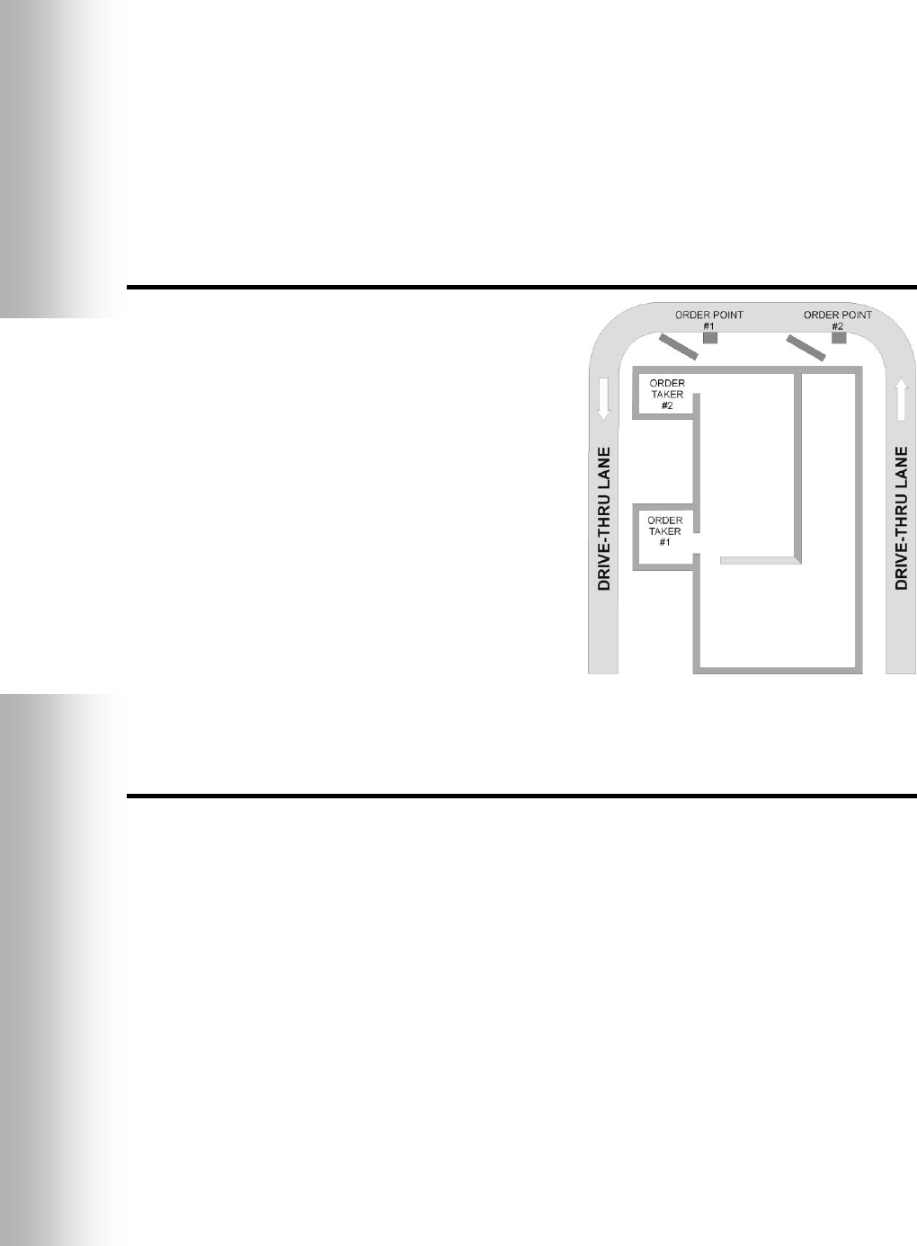
Tandem Operation
Tandem is a special case of
multiple-lane operation in
which a customer arriving at
Order Point #2 can be given
a “Please pull forward”
message if no customer is
present at Order Point #1.
Headset operation is the
same as described for dual-
lane operation.
Internal Communication
If using the BHF mode, the B channel remains open for hands-free
communication among crew members. If a customer arrives,
B-channel communication will automatically be interrupted to allow
communication with the customer.
If not using the BHF mode, to communicate internally with other
headset operators, press and hold the B button while talking. Release
when finished. In single-lane operations, up to four operators can
have conference-call type communication by all pressing the B
button. Everyone pressing the B button will hear each other without
interference.
In Dual-lane, Y-lane, Tandem or Single/A2 operation, if your system
was set up for “Split-B,” internal communication will be heard only by
headset operators in their lane. If your system was set up for
“Combined-B” operation, internal communication will be heard by all
operators in both lanes. Up to three operators can have conference-
call type communication by all pressing the B button. Everyone
pressing the B button will hear each other without interference. If a
car arrives in a lane while internal communication is taking place,
priority will be given to the respective A channel for customer
communication, which will reduce the number of internal
communication channels available.
Figure 7. Typical tandem drive-thru
NOTE:
In Tandem operation,
if Order Taker #2’s
headset is set in the Auto-
Hands-Free mode, the
“Please pull forward”
message will not be
played at Order Point #2.
If necessary, Order Taker
#2 will have to ask the
customer at Order Point
#2 to pull forward. If a
headset is turned off
while in the AHF mode, it
will automatically be reset
to its previous operating
mode.

14
Speed-Team Operation Mode
Speed-team operation is used during high-volume times. An order
taker wearing a headset relays orders from outside into the store,
using button A1, A2 or B.
Speed teams are only used in single or dual-lanes, not in tandem
drive-thrus.
Speed-Team Operation
To start speed-team operation, press the Menu button on the base
station LANE STATUS display, and then press the Operator mode
button on the MAIN MENU.
On the OPERATOR MODE display, press the Activate Speed Team
button to highlight ✔(on). To change back to normal operation,
return to the OPERATOR MODE display and press the Activate
Speed Team button to highlight −(off).
Press the Speed Team HELP button for further explanation.
If you have an external speed-team switch, you can select External
on the OPERATOR MODE display, and then use the optional remote
speed-team switch to go in and out of speed-team operation.
To save the setting, press the Back button.
CAUTION:
If Activate Speed Team is
✔
(on),
many base station functions
will be disabled. Vehicle arrival
tones and the customer’s voice
will not be heard during speed-
team operation. For normal
order taking, the Activate Speed
Team setting should be
−
(off).
NOTE:
The OPERATOR MODE
display shown here is for
single-lane operations.
In dual-lane operations, the
Activate dedicated mode
will also appear on the
OPERATOR MODE display.
See APPENDIX, Dedicated
Mode for explanation.

15
Message Center Operation
The Message Center is a central point at which messages can be
set up to be triggered by various events during designated time
periods, to be sent to customers at the speaker post or to crew
members via headsets or ceiling speakers.
Some messages are pre-named and pre-recorded. All messages
can be edited and re-recorded to meet your specific requirements.
The three types of messages are described below. The table on the
next page shows the names and contents of factory pre-set
messages. Following the table are detailed instructions of how to
set up your Message Center.
At the back of this manual you will find a Message Center Quick
Start Guide for planning your message settings.
Customer Greeter messages
Customer Greeter messages are heard by the customer at the
speaker post. They are typically used to greet customers and
inform them of promotional items. Customer Greeter messages
are pre-named but not pre-recorded, with the following exceptions;
the Store Closed message and Pull Forward message (only for
tandem drive-thrus) are pre-recorded. All Customer Greeter
messages can be renamed and recorded or re-recorded to meet
your store needs.
Reminder messages *
Reminder messages are heard by crew members in their headsets to
remind them when routine tasks need to be done. Reminder
messages can also be set to play in the ceiling speaker. There are
12 pre-named and pre-recorded Reminder messages that can be
named and recorded to meet your store needs. There are also 3
“Empty” messages that can be named and recorded as needed.
Reminder messages can be sent to all headsets or targeted only to
designated headsets.
Alert messages *
Alert messages (audio) can be heard by crew members in their
headsets to let them know about something that requires
attention, such as a door being left open or a customer arriving in
the store. Alert messages can be sent to all headsets or only to
designated headsets. Alert messages (audio) can also be set to
play in ceiling speakers. There are 6 Alert messages that can be
triggered by switches in the store that sense conditions such as
open doors, and 14 that can be triggered by PC Network commands.
Alert messages (email/text) can also be sent to designated email
recipients, smart phones and other email/texting devices with text
information to let the manager know about Alert events in the store.
HINT!
Before continuing, it is
important to consider
all the possible time periods
during which any of the
Message Center messages
need to be played in your
store. Up to 12 time periods
can be set up. You can use
the Message Center Settings
Worksheet at the back of this
manual. When you have
determined all the time
periods needed, go to the
Schedule Times section of
these instructions to set up
the time periods for your store
before continuing with the
Message Center settings. The
current time and date, and
store open and close times
should also be set before other
Message Center settings.
* Reminder and Alert messages can be assigned either Low or High Priority.
Low Priority – If currently playing, Low Priority messages will be terminated when any
of these three events occur: A press, B press, car arrival. After a Low Priority message
has been terminated, it will not play again until the next trigger event occurs.
High Priority – If currently playing, High Priority messages will be interrupted when
either of these two events occur: A press, B press. After the interruption has ended,
the message will attempt to play again to completion.
NOTE:
Message Center settings are
normally made or changed
only by authorized
personnel such as store
managers. Making changes
to Message Center settings
may require a password.
If a password is needed, see
APPENDIX, Access Control.

16
MESSAGE CENTER MESSAGES
NAME
CONTENT
CUSTOMER GREETER
All Day 1
Not pre-recorded.
All Day 2
Not pre-recorded.
Breakfast 1
Not pre-recorded.
Breakfast 2
Not pre-recorded.
Lunch 1
Not pre-recorded.
Lunch 2
Not pre-recorded.
Snack 1
Not pre-recorded.
Snack 2
Not pre-recorded.
Dinner 1
Not pre-recorded.
Dinner 2
Not pre-recorded.
Store Closed
Thank you for your visit, but we are currently closed.
Please visit us again during our normal business hours.
Pull Forward *
Hello, please pull forward to the next speaker. Thanks.
* (Tandem drive-thru only)
REMINDER
Hand Washing
Please wash your hands.
Sanitizer
Please change sanitizer solution.
DR Trash
Please check the dining room trash.
HACCP
Please complete the HACCP shift checklist.
Quality Check
Please complete the shift quality check.
Lot Check
Please complete a parking lot check.
Restroom Check
Please check the restrooms.
Pre-Rush
Please complete the pre-rush tasks for your
workstation.
Post-Rush
Please complete the post-rush tasks for your
workstation.
Headset Status
To check headset status, press and hold A2 and volume
down while turning on the power.
Change Language
To change headset prompt language, press and hold A1
and volume down while turning on the power.
Hands Free ON
To turn headset hands free mode on, press and hold B
and volume up while turning on the power.
Empty 1-3
Not pre-recorded.
ALERT
NAME
EVENT
CONTENT
Freezer Door
S1
The freezer door has been left open.
Cooler Door
S2
The cooler door has been left open.
Back Door
S3
The back door has been left open.
Lobby Door
S4
A guest has entered the lobby.
Empty
S5
Not pre-recorded.
Empty
S6
Not pre-recorded.
Empty
N1 – N14
Not pre-recorded.
Customer Greeter
messages are triggered
by detection of vehicles
in the drive-thru lane,
plus time and day.
Reminder messages
are triggered by time and
day only.
Alert messages are
triggered by input
signals, plus time and
day or Network events.
Under EVENT −
S# refers to a
switch-triggered alert.
N# refers to a
Network-triggered alert.

17
Customer Greeter Settings
To set up the time periods and locations for Customer Greeter
messages to be played, or to name and/or record Customer
Greeter messages, press the Menu button on the base station
LANE STATUS display and then, on the MAIN MENU press the
Message Center button.
Press the Customer Greeter button on the MESSAGE CENTER
MENU.
To select a message on the CUSTOMER GREETER display, press
the ▲(up) or ▼(down) button to scroll up or down to highlight the
desired message.
To edit the selected message, press the Edit button.
Rename Message
To change the name of the selected message, press the Rename
button on the EDIT CUSTOMER GREETER display.
On the Rename display, use the Erase button to clear characters
in the current name to change them. Use the ◄, ►, ▲ and ▼
buttons to move the highlight to a character you would like to use
in the name. Use the Sel (select) button to enter the highlighted
character in the name. When you are finished, press the Back
button to save the new name.
NOTE:
The CUSTOMER GREETER
and EDIT CUSTOMER
GREETER displays shown
here are for single-lane
operations.
For multiple-lane operations,
See APPENDIX, Customer
Greeter Messages.

18
Turn Message On/Off
Review or Record Message
To listen to the existing message, press the Review button on the
REVIEW/RECORD MESSAGE display. Follow the instructions
under READY TO REVIEW on the display. Press and hold the
headset B button. The message will be played only to the headset
where the B button is pressed.
To record a new message, press the Record button on the
REVIEW/RECORD MESSAGE display.
Follow the instructions under READY TO RECORD on the display.
You can record a message up to 16 seconds long while you are
pressing the headset B button. The Progress indicator will show
you how long you have been recording.
When you finish recording, release the B button and press the
Review button on the display, and follow the instructions under
READY TO REVIEW to confirm a successful recording.
NOTE:
Reviewed messages
are played to a
specific headset to
avoid interfering with
lane operations.
To review the existing selected
message, or to record a new
message, press the
Review/Record button on the
EDIT CUSTOMER GREETER
display.
To turn the selected message on
or off, press the Message button
on the EDIT CUSTOMER
GREETER display to highlight
either ✔(on) or −(off). Press the
Back button to save this setting.

19
Message Schedule
To choose the schedule for the selected message, press the
Schedule button on the EDIT CUSTOMER GREETER display.
On the SCHEDULE CUSTOMER GREETER display, press the
button for the day you want the selected message to be played.
On the SELECT SCHEDULE TIMES display, select the time period
when you want the selected message to play by pressing the ▲(up)
and ▼(down) buttons to scroll through the 12 available time
periods. When the desired time period is highlighted, press the
Edit button.
On the EDIT display, press the Scheduled button to turn the
message ✔(on) or −(off) for the selected time period. If you want
the message to be on or off during this time period every day,
press the Apply to all days? button to select Yes. If No is
selected, only the selected day will be affected by this change.
Press the Back button to save this setting.
NOTE:
To edit the Start and Stop
times for the time periods
listed on the SELECT
SCHEDULE TIMES
display, go to the
MESSAGE CENTER
MENU and select
Edit schedule times.
20
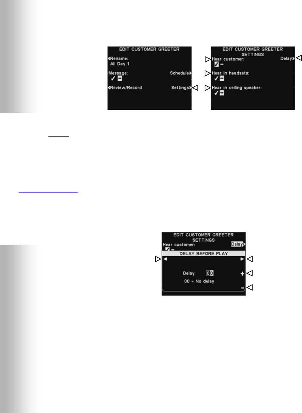
Message Playback Settings
To edit where the selected Customer message will be heard (in
addition to the speaker post), press the Settings button on the
EDIT CUSTOMER GREETER display.
On the EDIT CUSTOMER GREETER SETTINGS display, press the
button corresponding to the location where you would like the
selected message to be heard or not heard, to highlight ✔(on) or −(off).
If you select Hear customer: ✔(on), you will hear a customer at
the speaker post, together with the selected Customer Greeter
message. If you select Hear customer: −(off), you will not hear the
customer until the Customer Greeter message has completed.
The Hear in headsets and Hear in ceiling speaker settings allow
you to choose whether or not to hear the selected Customer
Greeter message in those locations.
If you would like a delay after the Customer Greeter message is
triggered until it begins playing, select Delay on the EDIT
CUSTOMER GREETER SETTINGS display. On the DELAY
BEFORE PLAY display, use the + and − buttons to change the
number in the highlighted box, and use the ◄ or ► button to
move the highlight to the opposite position.
When you are finished, press the Back button to save the setting.
NOTE:
Customer Greeter
messages are always
directed to the drive-thru
speaker in addition to
these settings. To stop
playback to the drive-thru
speaker requires setting
the Customer Greeter
volume to 0.
See Volume Adjustments.
For the message to be
heard at the drive-thru
speaker, the outbound
Customer Greeter volume
must be adjusted, and
then checked at the
speaker post.
21
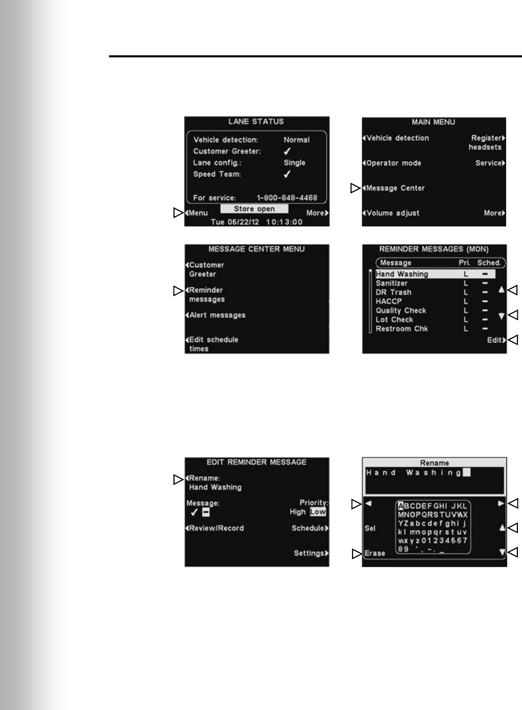
Reminder Message Settings
To set up the time periods and locations for Reminder Messages to
be played, or to name and/or record Reminder Messages, press
the Menu button on the base station LANE STATUS display and
then, on the MAIN MENU press the Message Center button.
Press the Reminders button on the MESSAGE CENTER MENU.
To select a message on the REMINDER MESSAGES display, press
the ▲(up) or ▼(down) button to scroll up or down to highlight the
desired message. To edit the highlighted message, press the Edit
button.
Rename Message
To change the name of the selected message, press the Rename
button on the EDIT REMINDER MESSAGE display.
On the Rename display, use the Erase button to clear characters
in the current name to change them. Use the ◄, ►, ▲ and ▼
buttons to move the highlight to a character you would like to use
in the name. Use the Sel (select) button to enter the highlighted
character in the name. When you are finished, press the Back
button to save the new name.

22
Turn Message On/Off
Review or Record Message
To listen to the existing message, press the Review button on the
REVIEW/RECORD MESSAGE display. Follow instructions under
READY TO REVIEW on the display. Press and hold the headset B
button. The message will be played only to the headset where the
B button is pressed.
To record a new message, press the Record button on the
REVIEW/RECORD MESSAGE display.
Follow the instructions under READY TO RECORD on the display.
You will have up to 16 seconds to record a message while you are
pressing the headset B button. The Progress indicator will show
you how long you have been recording.
When you finish recording, release the B button and press the
Review button on the display, and follow the instructions under
READY TO REVIEW to confirm a successful recording.
NOTE:
Reviewed messages
are played to a
specific headset to
avoid interfering with
lane operations.
To review the existing selected
message, or to record a new
message, press the
Review/Record button on the
EDIT REMINDER MESSAGE
display.
To turn the selected message on
or off, press the Message button
on the EDIT REMINDER
MESSAGE display to highlight
either ✔(on) or −(off). Press the
Back button to save this setting.

23
Message Priority
Reminder messages can be assigned a high or low priority.
To set message priority, press the Priority button on the EDIT
REMINDER MESSAGE display to highlight either High or Low.
Press the Back button to save this setting.
Message Schedule
To choose the schedule for the selected message , press the
Schedule button on the EDIT REMINDER MESSAGE display.
On the SCHEDULE REMINDER MESSAGE display, press the
button for the day you want the selected message to be played.
On the SELECT SCHEDULE TIMES display, select the time
period(s) when you want the selected message to play by pressing
the ▲(up) and ▼(down) buttons to scroll through the 12 available
time periods. When the desired time period is highlighted, press
the Edit button.
On the EDIT display, press the Scheduled button to turn the
message ✔(on) or −(off) for the selected time period. If you want
the message to be on or off during this time period every day,
press the Apply to all days? button to select Yes. If No is
selected, only the selected day will be affected by this change.
Press the Back button to save this setting.
NOTE:
Reminder messages are
triggered to play at the
beginning of their selected
schedule time period(s).
NOTE:
If the priority is set Low,
the message may play to
completion or be
terminated by either an A
or B button being pressed
on any headset, or by a
car arrival on a given lane.
If the priority is set High,
the message will play to
completion. If a high
priority message is
interrupted by an A or B
button being pressed on
any headset for a given
lane, it will retry until it is
able to play to completion.
NOTE:
To edit the Start and Stop
times for the time periods
listed on the SELECT
SCHEDULE TIMES
display, go to the
MESSAGE CENTER
MENU and select
Edit schedule times.
24
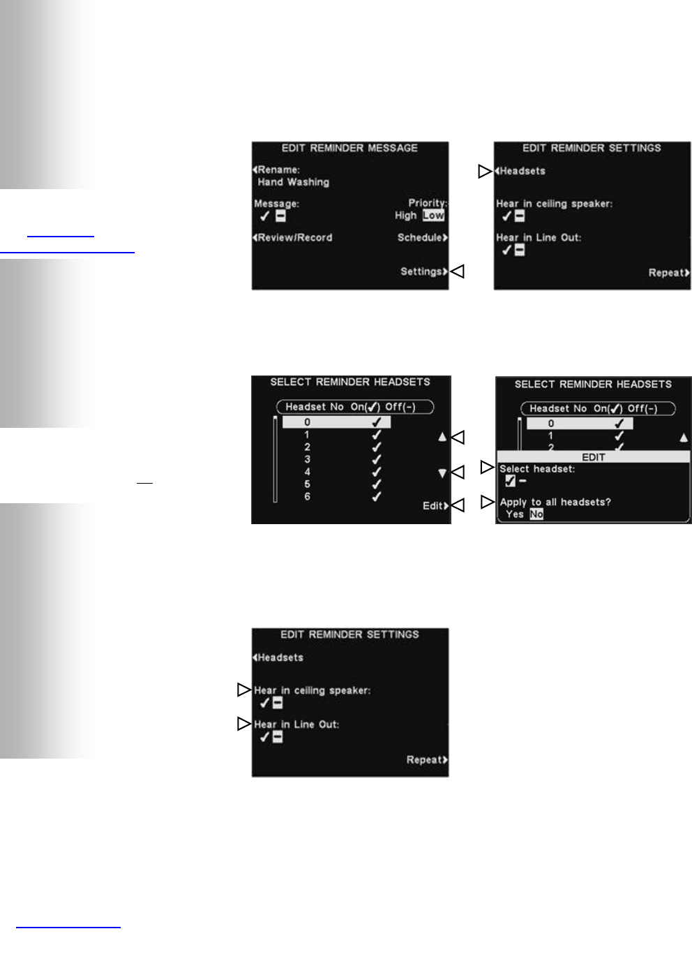
Message Playback Settings
Routing − To choose where the selected Reminder message will be
heard, press the Settings button on the EDIT REMINDER
MESSAGE display, and then press the Headsets button on the
EDIT REMINDER SETTINGS display.
On the SELECT REMINDER HEADSETS display, use the ▲(up)
and ▼(down) buttons to select a headset number for which you
would like to turn the selected Reminder message on or off, and
then press the Edit button.
To turn the message on or off in the selected headset, press the
Select headset button on the EDIT display to highlight ✔(on) or
−(off). To turn the message on or off in all headsets, press the Apply
to all headsets? button to highlight Yes or No.
To save this setting, press the Back button.
To have the selected Reminder message heard or not heard in the
ceiling speaker(s), press the Hear in ceiling speaker button to
highlight ✔(on) or −(off).
To have the selected Reminder message heard or not heard in the line
out(s), press the Hear in Line Out button to highlight ✔(on) or −(off).
NOTE:
After selecting
✔
(on), to hear
the Reminder message in the
ceiling speaker or Line Out,
you must also be sure their
volume is set high enough
for the message to be heard.
To do this, return to the
MAIN MENU and select
Volume adjust to make the
necessary adjustments.
NOTE:
By default, Reminder
messages play to all
headsets.
For multiple-lane
operations,
see Appendix,
Reminder Messages.

25
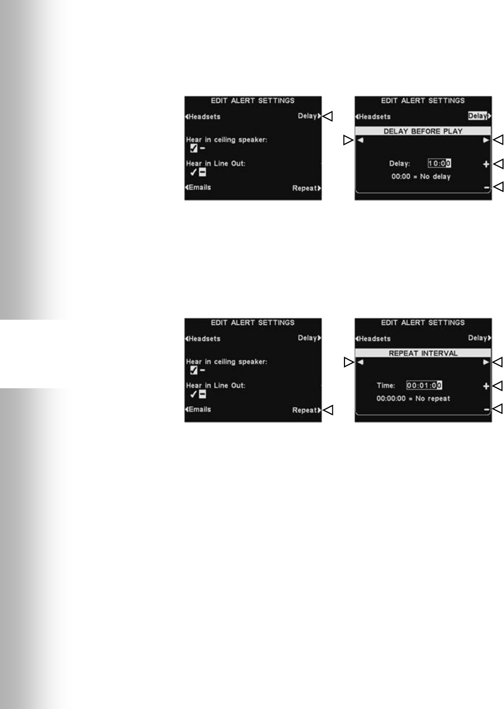
Repeats − To have the Reminder message play repeatedly at
selected intervals, press the Repeat button on the EDIT
REMINDER SETTINGS display. On the REPEAT INTERVAL
display, use the ◄ or ► button to move the highlight left or right
in the Time field for hours, minutes or seconds (HH:MM:SS), and
use the + and − buttons to change the number in the highlighted
box. Setting the repeat interval to all 0’s disables repeats.
To save this setting, press the Back button.

26
Alert Message Settings
To set up the time periods and locations for Alert Messages to be
played, or to name and/or record Alert Messages, press the Menu
button on the base station LANE STATUS display and then, on
the MAIN MENU press the Message Center button.
Press the Alert messages button on the MESSAGE CENTER MENU.
To select a message on the ALERT MESSAGES display, press the
▲(up) and ▼(down) button to scroll up or down to highlight the
desired message. To edit a message, select the message and press
the Edit button.
Rename Message
To change the name of the selected message, press the Rename
button on the EDIT ALERT MESSAGE display.
On the Rename display, use the Erase button to clear characters
in the current name to change them. Use the ◄, ►, ▲ and ▼
buttons to move the highlight to a character you would like to use
in the name. Use the Sel (select) button to enter the highlighted
character in the name. When you are finished, press the Back
button to save the new name.

27
Turn Message On/Off
Review or Record Message
To listen to the existing message, press the Review button on the
REVIEW/RECORD MESSAGE display. Follow instructions under
READY TO REVIEW on the display. Press and hold the headset B
button. The message will be played only to the headset pressing the
B button.
To record a new message, press the Record button on the
REVIEW/RECORD MESSAGE display.
Follow the instructions under READY TO RECORD on the display.
You will have up to 10 seconds to record a message while you are
pressing and holding the headset B button. The Progress indicator
will show you how much time you have left. When you finish
recording, release the headset B button and press the Review
button on the display, and follow the instructions under READY
TO REVIEW to confirm a successful recording.
NOTE:
Reviewed messages
are played to a
specific headset to
avoid interfering with
lane operations.
To review the existing selected
message, or to record a new
message, press the
Review/Record button on the
EDIT ALERT MESSAGE
display.
To turn the selected message on
or off, press the Message button
on the EDIT ALERT MESSAGE
display to highlight either ✔(on)
or −(off). Press the Back button
to save this setting.

28
Message Priority
Message Schedule
To choose the schedule for the selected message, press the
Schedule button on the EDIT ALERT MESSAGE display.
On the SCHEDULE ALERT MESSAGE display, press the button
for the day you want the selected message to be played.
On the SELECT SCHEDULE TIMES display, select the time period
when you want the selected message to play by pressing the ▲(up)
and ▼(down) buttons to scroll through the 12 available time periods.
When the desired time period is highlighted, press the Edit button.
On the EDIT display, press the Scheduled button to turn the
message ✔(on) or −(off) for the selected time period. If you want
the message on or off during this time period every day, press the
Apply to all days? button to select Yes. If No is selected, only the
selected day will be affected by this change.
To save these settings, press the Back button.
NOTE:
To edit the Start and Stop
times for the time periods
listed on the SELECT
SCHEDULE TIMES
display, go to the
MESSAGE CENTER
MENU and select
Edit schedule times.
NOTE:
If the priority is set Low,
the message may play to
completion or be
terminated by either an A
or B button being pressed
on any headset, or by a
car arrival in a given lane.
If the priority is set High,
the message will play to
completion. If a high
priority message is
interrupted by an A or B
button being pressed on
any headset for a given
lane, it will retry until it is
able to play to completion.
Alert messages can be
assigned a high or low priority.
To set message priority, press
the Priority button on the
EDIT ALERT MESSAGE
display to highlight either
High or Low. Press the Back
button to save this setting.

29
Message Playback Settings
Routing − To choose where the selected Alert message will be
heard, press the Settings button on the EDIT ALERT MESSAGE
display, and then press the Headsets button on the EDIT ALERT
SETTINGS display.
On the SELECT ALERT HEADSETS display, use the ▲(up) and
▼(down) buttons to select a headset number for which you would
like to turn the selected Alert message on or off, and then press the
Edit button.
To turn the message on or off in the selected headset, press the
Select headset button on the EDIT display to highlight ✔(on) or
−(off). To turn the message on or off in all headsets, press the Apply
to all headsets? button to highlight Yes or No, and then press the
Back button.
To have the selected Alert message heard or not heard in the
ceiling speaker(s), on the EDIT ALERT SETTINGS display, press
the Hear in ceiling speaker button to highlight ✔(on) or −(off).
To have the selected Alert message heard or not heard in the line
out(s), press the Hear in Line Out button to highlight ✔(on) or −(off).
For multiple-lane
operations,
see Appendix,
Alert Messages.
NOTE:
After selecting
✔
(on), to hear
the Alert message in the
ceiling speaker or Line Out,
you must also be sure their
volume is set high enough
for the message to be heard.
To do this, return to the
MAIN MENU and select
Volume adjust to make the
necessary adjustments.
30
Delay − To set a delay after the Alert message is triggered until it
begins playing, press the Delay button. On the DELAY BEFORE
PLAY display, use the ◄ or ► button to move the highlight left or
right in the Delay field for minutes and seconds (MM:LL), and use
the + and − buttons to change the number in the highlighted box.
To save these settings, press the Back button.
Repeats − To have the Alert message play repeatedly at selected
intervals, press the Repeat button on the EDIT ALERT SETTINGS
display. On the REPEAT INTERVAL display, use the ◄ or ►
button to move the highlight left or right in the Time field for
hours, minutes or seconds (HH:MM:SS), and use the + and −
buttons to change the number in the highlighted box.
Setting the repeat interval to all 0’s disables repeats.
To save these settings, press the Back button.
NOTE:
The repeat interval does not
apply to emails, since they
are not repeated for a given
message.

31
Alert Message Email
To compose an email message to be sent to designated recipients
when the selected Alert is triggered, select Message Text on the
EDIT ALERT MESSAGE display.
To edit the email text, on the Message Text display, use the Erase
button to clear characters if there is a current email you want to
change. Use the ◄, ►, ▲ and ▼ buttons to move the highlight to
a character you would like to use in the new email text. Use the
Sel (select) button to enter the highlighted character in the
message. To save the email text, press the Back button.
To have the selected Alert message sent to desired email addresses,
press the Emails button on the EDIT ALERT SETTINGS display.
On the SELECT EMAIL DESTINATIONS display, use the ▲(up)
and ▼(down) buttons to select an email address for which you
would like to turn the selected Alert message on or off, and then
press the Edit button.
To select/deselect the email destination that will receive the email
message, press the Select email destination button on the EDIT
display to highlight ✔(on) or −(off).
To select/deselect all email destinations, press the Apply to all
email destinations? button to highlight Yes or No, and then
press the Back button.
NOTE:
You may be able to select
up to 7 email destinations,
depending on your server.
NOTE:
Email destination addresses
must have been entered
correctly, otherwise no
emails will be sent for a
given alert trigger. Also,
emails must have been
turned on, and the correct
SMTP Server and SMTP Port
must have been entered.
Refer to Email/Texting on
page 50.

32
To edit the selected email address, press the Edit destination
address button on the EDIT display. On the EDIT DESTINATION
ADDRESS display, use the Erase button to clear characters in the
current email address to change them. Use the ◄, ►, ▲ and ▼
buttons to move the highlight to a character you would like to use
in the address. Use the Sel (select) button to enter the highlighted
character in the address.
When you are finished, press the Back button to save the new
email address.

33
Schedule Times
To set up all the time periods during each day, in which Message
Center messages can be scheduled, press the Menu button on the
base station LANE STATUS display and then, on the MAIN MENU
press the Message Center button.
Press the Edit schedule times button on the MESSAGE CENTER
MENU.
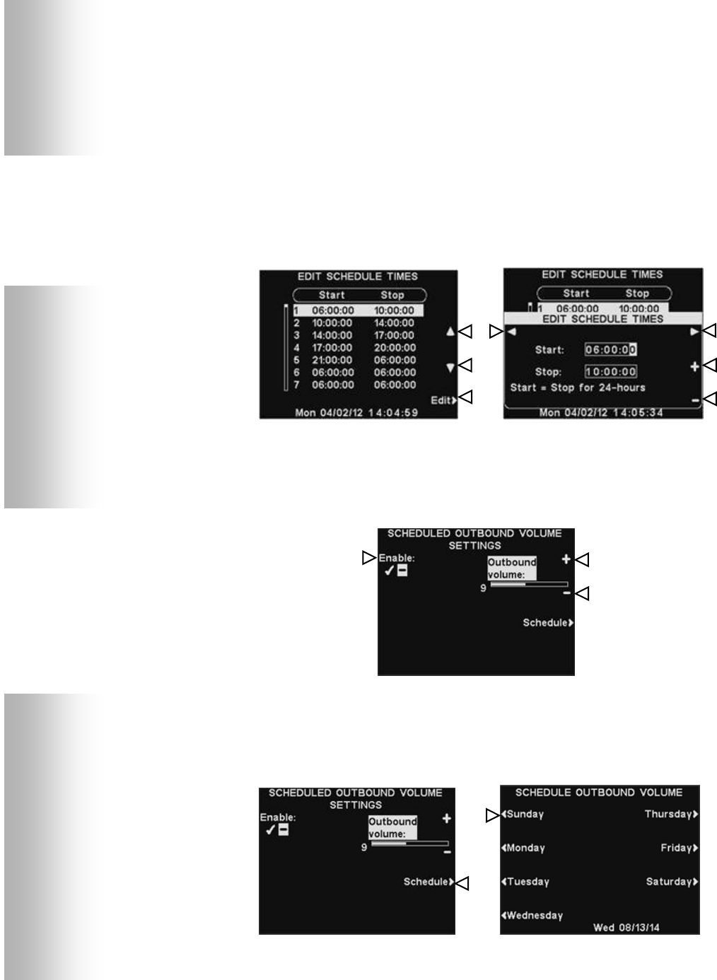
There are 12 possible time periods. To select a time period to be
edited, use the ▲(up) and ▼(down) buttons to scroll through the
12 available time periods on the EDIT SCHEDULE TIMES display.
When the desired time period is highlighted, press the Edit
button.
On the drop-down EDIT SCHEDULE TIMES display, to edit the
Start or Stop time, use the ◄ and ► buttons to move the highlight
in the Start or Stop field, and use the + and − buttons to change
the highlighted numbers. To move from one field to the other,
repeat pressing the ◄ or ► button until the highlight moves from
one field to the other.
To save these settings, press the Back button.
NOTE:
Times are in
24 hour format.
example:
0500 = 5 A.M.
1700 = 5 P.M.
0000 = Midnight
NOTE:
You can schedule
a full 24-hour
period by setting
Start and Stop
times the same.

34
Volume Adjustments
To adjust the volume of inbound and outbound audio, alert tones
and message repeater messages, on the base station LANE STATUS
display, select Menu and then, on the MAIN MENU select Volume
adjust.
Press the buttons on the left side of the VOLUME MENU to select
which volume you want to adjust.
In/Out-bound Audio Volume
On the IN/OUTBOUND VOLUME display, select which volume you
would like to adjust, and then use the + and − buttons to raise and
lower the volume level. The first two settings adjust the audio level
to and from the outside speaker/microphone and the third setting
adjusts the level of the outbound Customer Greeter message from
the Message Center. If a volume is set to 0, that function is turned
off and no audio is heard at all. For dual-lane operations, these
settings will be available for Lane 1 and Lane 2.
To automatically change the volume level of the outside speaker
(for example, to lower the volume at night), under Scheduled
outbound, select Schedules and then Settings as follows.
NOTE:
Volume adjustments are
normally made or changed only
by authorized personnel such
as store managers. Making
changes to volume adjustments
may require a password.
If a password is needed, see
APPENDIX, Access Control.
In multiple-lane configurations,
the VOLUME MENU display
will be divided by Lanes.
Settings will be similar to
those shown for a single lane.
NOTE:
This Outbound audio level
will be active whenever any
scheduled outbound audio
level is not enabled.
35
Schedules
There are 7 possible time periods. These time periods will only apply
to scheduled outbound volume level settings. They will not affect
other message schedules.
To select a time period to be edited, use the ▲(up) and ▼(down)
buttons to scroll through the available time periods. When the
desired time period is highlighted, press the Edit button.
On the drop-down EDIT SCHEDULE TIMES display, to edit the
Start or Stop time, use the ◄ and ► buttons to move the highlight in
the Start or Stop field, and use the + and − buttons to change the
highlighted numbers.
To move from one field to the other, repeat pressing the ◄ or ►
button until the highlight moves from one field to the other.
To save these settings, press the Back button.
Settings
To raise or lower an outbound volume level that is active during
selected days and times, use the + and − buttons for Outbound
volume.
Schedule
To select days when these outbound volume settings can be enabled,
on the SCHEDULED OUTBOUND VOLUME SETTINGS display,
select Schedule.
On the SCHEDULE OUTBOUND VOLUME display, select the day
you want to schedule the outbound volume setting.
NOTE:
Times are in
24 hour format.
example:
0500 = 5 A.M.
1700 = 5 P.M.
0000 = Midnight
NOTE:
This Outbound volume level
will only be active during
scheduled days and times,
and only if it is enabled.
To enable this Outbound
volume level during
scheduled times, select
Enable to highlight the
✔
.
36
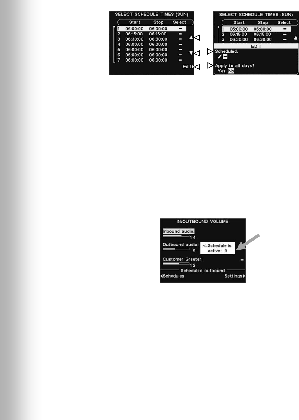
On the SELECT SCHEDULE TIMES display, select the time period
you want to apply to this day by pressing the ▲(up) and ▼(down)
buttons to scroll through the 7 available time periods. When the
desired time period is highlighted, press the Edit button.
On the EDIT display, press the Scheduled button to highlight ✔(on)
or − (off) for the selected time period. If you want the outbound
volume setting to be on or off during this time period every day, press
the Apply to all days? button to highlight Yes. If No is highlighted,
only the selected day will be affected by this change.
If you need help, press the Help button.
To save these settings, press the Back button.
CONFIRMATION
During the day and time any outbound volume setting is scheduled,
you can confirm its current activation and level by viewing it in the
white box on the IN/OUTBOUND VOLUME display.
37
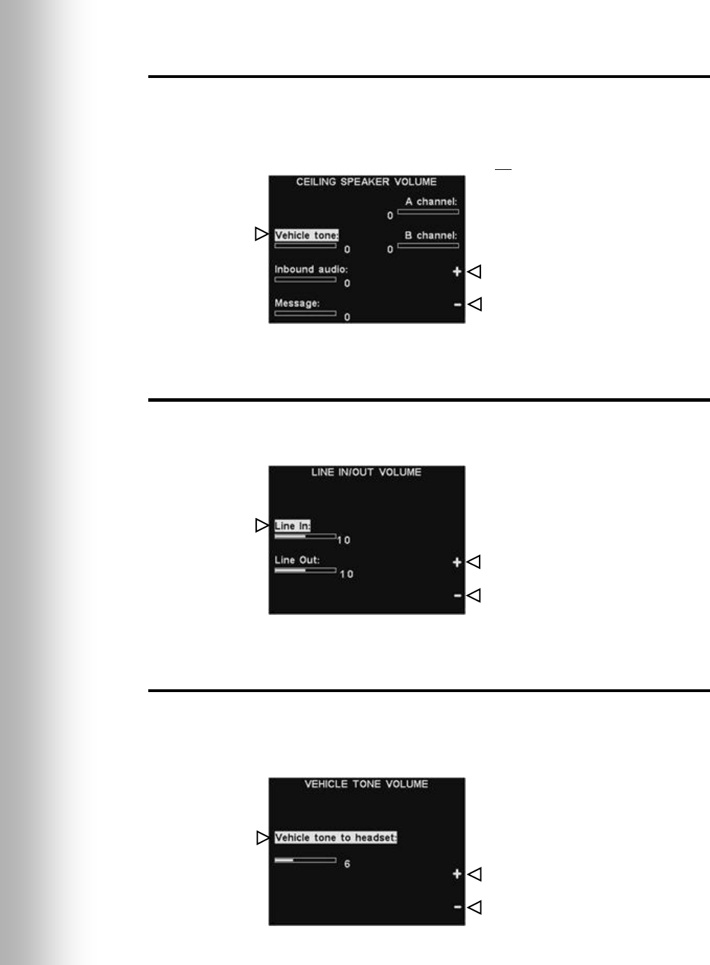
Ceiling Speaker Volume
To raise and lower the volume levels heard from the ceiling speaker,
select Ceiling speaker from the VOLUME MENU and then on the
IN/OUTBOUND VOLUME display, select which volume you would like
to adjust and use the + and − buttons. If a volume is set to 0, that
function is effectively turned off and no audio will be heard at all.
To save these settings, press the Back button.
Line In/Out
To raise or lower the volume level to or from any device connected to
the base station line output, select Line In or Line Out on the LINE
IN/OUT VOLUME display and then use the + and – buttons.
To save these settings, press the Back button.
Vehicle Tone in Headset
The VEHICLE TONE VOLUME setting only adjusts the level of alert
tones heard in the headsets.
To raise and lower the volume level of alert tones, use the + and –
buttons.
To save these settings, press the Back button.

38
Wired Backup System Operation
In order to use a Wired Backup System, you must have a Switcher
Board (optional) in your base station. If you have a Switcher
Board, you will find a switch on the bottom of your base station as
shown in Figure 9.
If you have a single lane drive-thru operation, you will find one
switch in the Lane 1 position
If you have a dual lane drive-thru operation, you may have two
Switcher Boards in your base station, in which case you will find
two switches on the bottom of your base station, one for Lane 1
and another for Lane 2.
To use the Wired Backup System, place the switch for Lane 1
and/or Lane 2 in the Backup (In) position.
When you have finished using the Wired Backup System, return
the switch to the Wireless (Out) position.
Figure 8. Wired backup switches on bottom of base station

39
Vehicle Detection
You can test the vehicle detector function by simulating a vehicle
arrival at the speaker post or menu board.
Before doing this, be sure there is no car (or metal object) at the
detection point.
Press the Menu button on the base station LANE STATUS display
and then press the Vehicle detection button on the MAIN MENU.
On the VEHICLE DETECTION display, press the Mode button to
select Override. This will cause the vehicle alert tone to be played
in headsets, followed by inbound audio from the outside speaker.
If enabled, a Customer Greeter message will also be played. To
return to normal operation, press the Mode button again to select
Normal.
If you experience a problem with vehicle detection, such as the
inbound audio not shutting off from the outside speaker or no
alert tone when a vehicle arrives, you can reset the Vehicle
Detector by pressing the Reset detector button on the VEHICLE
DETECTION display, and then pressing the Yes button to reset
Vehicle Detector(s).
After Reset completed appears and disappears on the display,
press the Back button to exit.
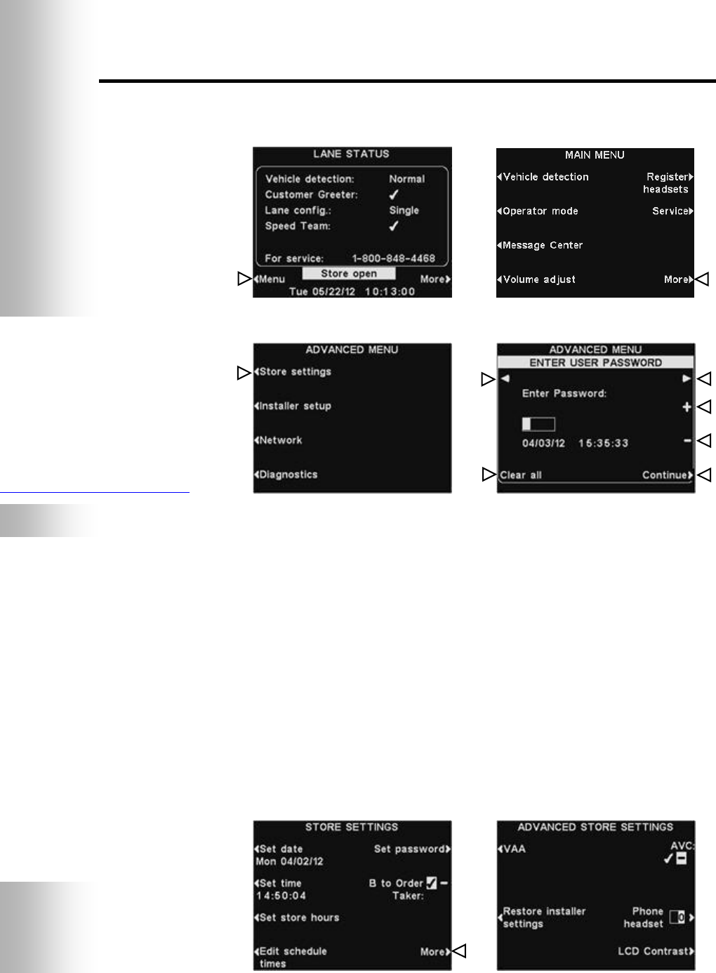
40
Store Settings
To access Store Settings, press the Menu button on the base
station LANE STATUS display and then press the More button on
the MAIN MENU.
On the ADVANCED MENU, press the Store settings button.
User Password
If you need a password, the ENTER USER PASSWORD display will
appear. If you do not need a password, the STORE SETTINGS
display shown below will appear immediately.
If you have a password, use the ◄ and ► buttons to move the
highlighted box left and right in the Enter Password field, and use
the + button to put alphabetic characters in the box, or the − button
to put numeric characters in the box. Each time you have entered a
character of your password, press the ► button to move the
highlighted box to the next position and enter the next character. If
you want to start over with a new password, press the Clear all
button. After entering your entire password, press the Continue
button to view the STORE SETTINGS display.
To view additional ADVANCED STORE SETTINGS, press the More
button.
NOTE:
Store settings are normally
made or changed only by
authorized personnel such
as store managers.
Making changes to store
settings may require a
password.
If a password is needed, see
APPENDIX, Access Control.
NOTE:
To set a password for
the first time, press the
Set Password button on
the STORE SETTINGS
display and use the ◄,
►, + and − buttons to
Enter new password
on the SET USER
PASSWORD display.
When you are finished,
press the Back button to
save the password.
In the future, the
password will be
required to access
Message Center,
Network, Volume
Settings and Store
Settings.

41
Set Date or Time
To make changes to the date or time settings, press the Set date or
Set time button on the STORE SETTINGS display.
On the SET DATE or SET TIME display, use the ◄ and ► buttons
to move the highlight in the Date or Time field, and use the + and −
buttons to change the highlighted numbers.
To save these setting, press the Back button.
Set Store Hours
To make changes to the store hours for any day, press the Set
store hours button on the STORE SETTINGS display.
Press the button next to the day you would like to change. Use the ◄
and ► buttons to move the highlight in the Open or Close field, and
use the + and − buttons to change the highlighted numbers. To move
from one field to the other, repeat pressing the ◄ or ► button until the
highlight moves from one field to the other. If you want these store
hours to apply to every day, press the Copy button and then press the
Apply to all days? button to highlight Yes. If No is highlighted, these
store hours will apply only to the selected day.
To save these settings, press the Back button.
HINT!
When setting the time,
set it a little in advance
of the known correct time
and then, one second
before the correct time
matches the setting, press
the Back button to restart
the clock.
NOTE:
All times are in 24-hour format.
NOTE:
If your store is open 24
hours, set the Open time
the same as the Close time.

42
Edit Schedule Times
Up to 12 Schedule Times can be set to establish periods in which
messages can be scheduled from the Message Center. Schedule
Times can be edited as needed. To make changes to the Schedule
Times, press the Edit schedule times button on the STORE
SETTINGS display.
On the EDIT SCHEDULE TIMES display, press the ▲(up) and
▼(down) buttons to move up and down the list of time periods.
You can continue pressing the ▼(down) button past 7 until you reach
12.
When the time period you would like to change is highlighted, press
the Edit button.
Use the ◄ and ► buttons to move the highlight in the Start or
Stop field, and then use the + and − buttons to change the
highlighted numbers. To move from one field to the other, repeat
pressing the ◄ or ► button until the highlight moves beyond the
end of one field and into the other.
To save these settings, press the Back button.
NOTE:
The EDIT SCHEDULE
TIMES display can also
be accessed through the
MESSAGE CENTER.
NOTE:
If your store is open, and
you want a schedule to
run for 24 hours, set the
Stop time the same as
the Start time.
NOTE:
Changing these time periods
will affect all Message Center
message schedules.

43
Set User Password
The User password is used to protect the Message Center, Network,
Volume Settings and Store Settings menus. This password is not
the same as the Installer Password that is used to protect the
Installer Settings.
For security purposes, you may need to change the password
periodically or when someone’s employment terminates. To do this,
press the Set password button on the STORE SETTINGS display.
The current password will be shown in the Enter new password
field on the SET USER PASSWORD display.
Use the ◄ and ► buttons to move the highlighted box in the
Enter New field. Use the + button to put alphabetic characters in
the highlighted box, or the − button to put numeric characters in
the highlighted box. Continuing down from A will take you to
numeric characters. Continuing up from 9 will take you to
alphabetic characters. Press the ► button to move the highlighted
box to the next position and enter the next character. If you want
to start over with a new password, press the Clear all button. After
entering the entire new password, press the Back button twice to
save the new password and return to the ADVANCED MENU.
NOTE:
See APPENDIX, Access
Control for a description of
how passwords are used to
control access to EOS|HD
menus.

44
B to Order Taker
The B to Order Taker feature allows the Order Taker to hear
(or not hear) B button communication during A button
communication with a customer.
Press the B to Order Taker button on the STORE SETTINGS
display to select ✔(on) to allow the Order Taker to hear B button
communication while pressing an A button. If you select −(off), the
Order Taker will not hear B button communication while pressing
an A button.
To save this setting, press the Back button.

45
VAA Adjustment
VAA settings can be adjusted to eliminate echo, feedback or
fluctuating inbound audio levels.
To turn the VAA feature on/off, or to adjust VAA levels, press the
More button on the STORE SETTINGS display. On the
ADVANCED STORE SETTINGS display, press the VAA button.
VAA On or Off:
To turn the VAA feature on or off, press the VAA button to
highlight ✔(on) or −(off).
VAA Sensitivity Level:
This is the volume level of the order taker’s voice required to activate
the VAA circuit. If speaking to the customer does not automatically
reduce the inbound level, press the VAA sensitivity button and
then press the + and − buttons until the inbound audio is reduced
while you are speaking to the customer, and returns to normal when
you stop speaking.
VAA Attenuation Level:
This is the amount that the inbound volume level is reduced when
the order taker speaks to the customer. If the order taker cannot
hear the inbound audio at all while speaking, the VAA
attenuation can be adjusted to a lower level. To make this
adjustment, press the VAA attenuation button and then press the
+ and − buttons until the desired level is reached. If you do not
want any attenuation, turn off VAA without adjusting this setting.
NOTE:
If you have a multiple-lane
drive-thru operation, you will
see VAA Lane 1 and VAA
Lane 2 on the ADVANCED
STORE SETTINGS display.
You may need to make this
adjustment for each lane.

46
Restore Installer Settings
To delete all of your custom settings and return to the original
settings made by the EOS|HD installer, press the Restore
installer settings button on the ADVANCED STORE SETTINGS
display, and then press the Restore button on the RESTORE
INSTALLER SETTINGS display. The base will automatically reset
and restore the installer settings.
Automatic Volume Control
When the Automatic Volume Control (AVC) is on, the volume level
at the outside speaker will be automatically adjusted to compensate
for environmental noise at the speaker post. When there is
excessive noise, the level of the order taker’s voice in the speaker
will be adjusted up. When it is quiet in the drive-thru area, the level
will be adjusted down.
To turn the Automatic Volume Control on or off, press the More
button on the STORE SETTINGS display, and then press the AVC
button on the ADVANCED STORE SETTINGS display to highlight
✔(on) or −(off).
NOTE:
If you have a multiple-lane
drive-thru operation, you will
see AVC Lane 1 and AVC
Lane 2 on the ADVANCED
STORE SETTINGS display.
Push either button to turn
AVC on or off in each lane.
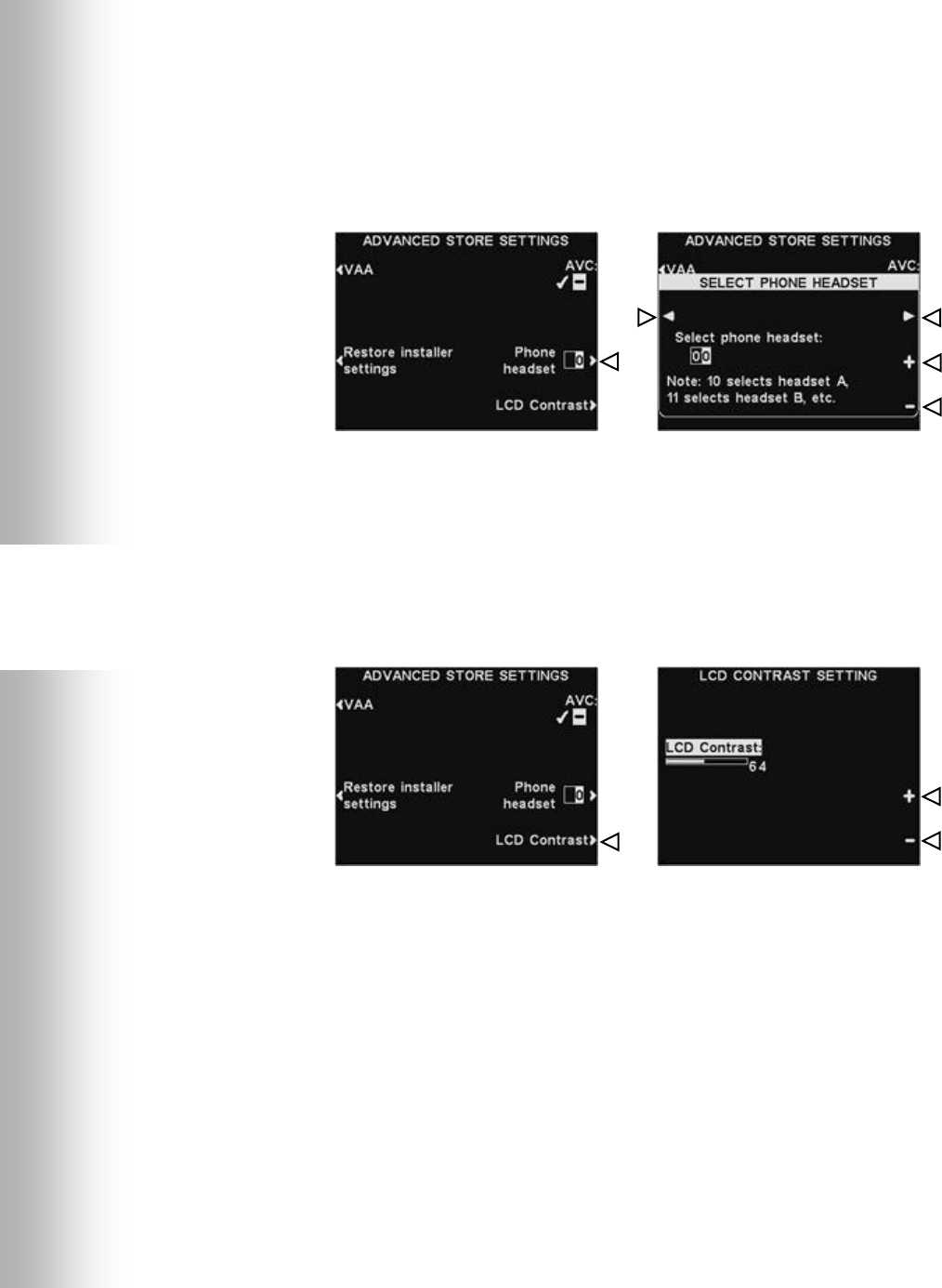
47
Phone Headset
If there is an HME Telephone Interface connected to your base
station, you can assign one headset to receive incoming telephone
calls. To do this, press the Phone headset button on the
ADVANCED STORE SETTINGS display. On the SELECT PHONE
HEADSET display, use the ◄ and ► buttons to move the highlight
in the Select phone headset field, and then use the + and −
buttons to enter number of the headset.
To save these settings, press the Back button.
LCD Contrast
To adjust the light/dark contrast of the base station display, press
the More button on the STORE SETTINGS display. On the
ADVANCED STORE SETTINGS display, press the LCD Contrast
button and then press the + (lighter) and − (darker) buttons to adjust
the contrast. When you are finished, press the Back button as
needed to save the setting and return to the desired display.
NOTE:
The LCD contrast is set
at the factory, and will
normally not need to be
adjusted.
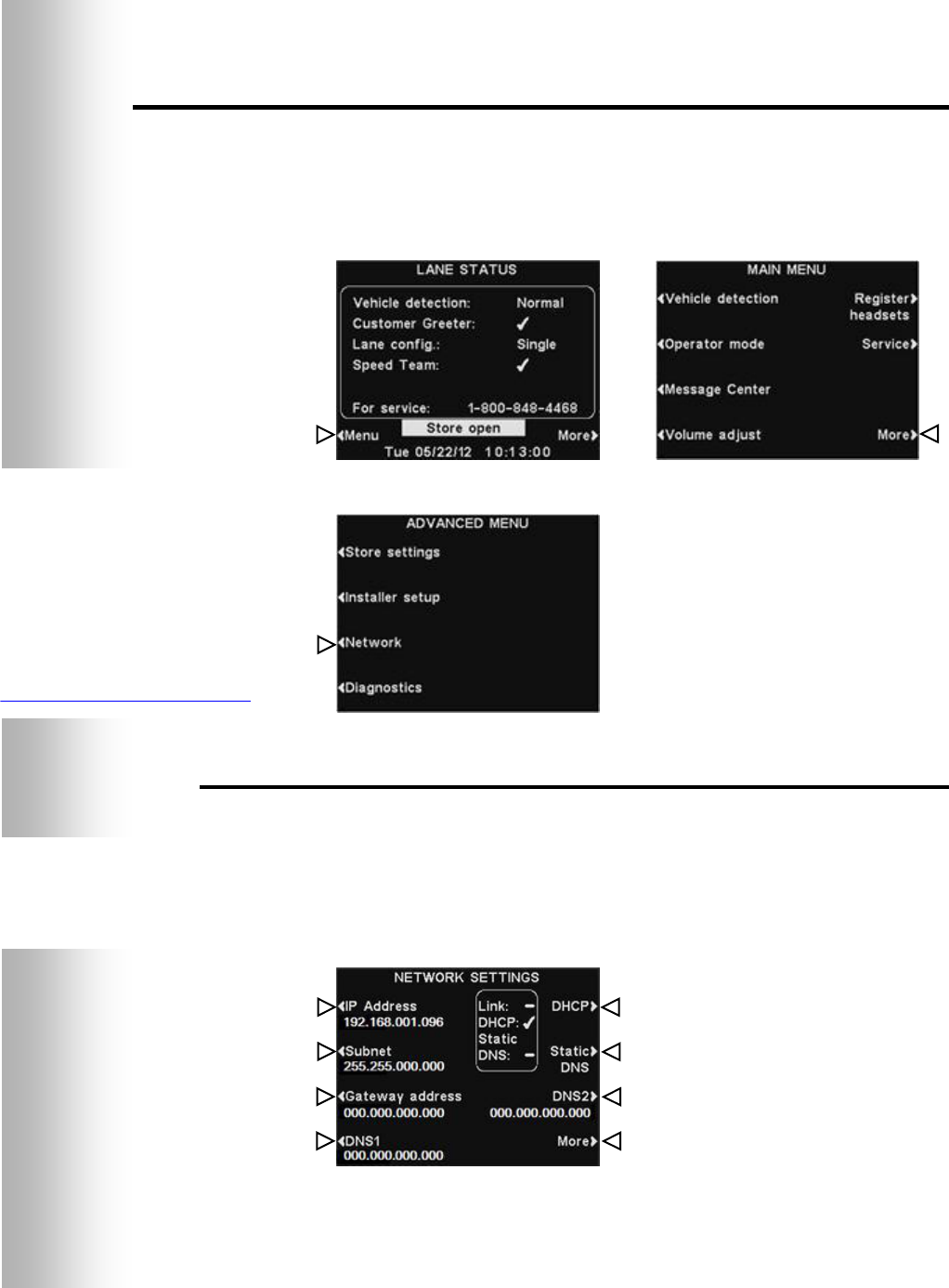
48
Network Settings
If your base station is connected to a computer network, the
network settings were set up by the EOS|HD installer. If you need
to contact HME Technical Support regarding any problem with your
network connection, you may be asked to make changes to the
network settings. To do this, select the Menu button on the LANE
STATUS display and then select More on the MAIN MENU.
Press the Network button on the ADVANCED MENU display, to open
the NETWORK SETTINGS display.
Basic Network Settings
On the NETWORK SETTINGS display, you must press the button
for each item you are requested to change. Each button pushed will
cause a display to open, where you may be requested to enter the
necessary address for network communication. If you push the
More button, the ADVANCED NETWORK SETTINGS display will
appear with additional settings.
NOTE:
Some Network Settings
changes will cause the
base to automatically reset.
NOTE:
Network settings are
normally made or changed
only by authorized personnel
such as store managers.
Making changes to Network
settings may require a
password.
If a password is needed, see
APPENDIX, Access Control.
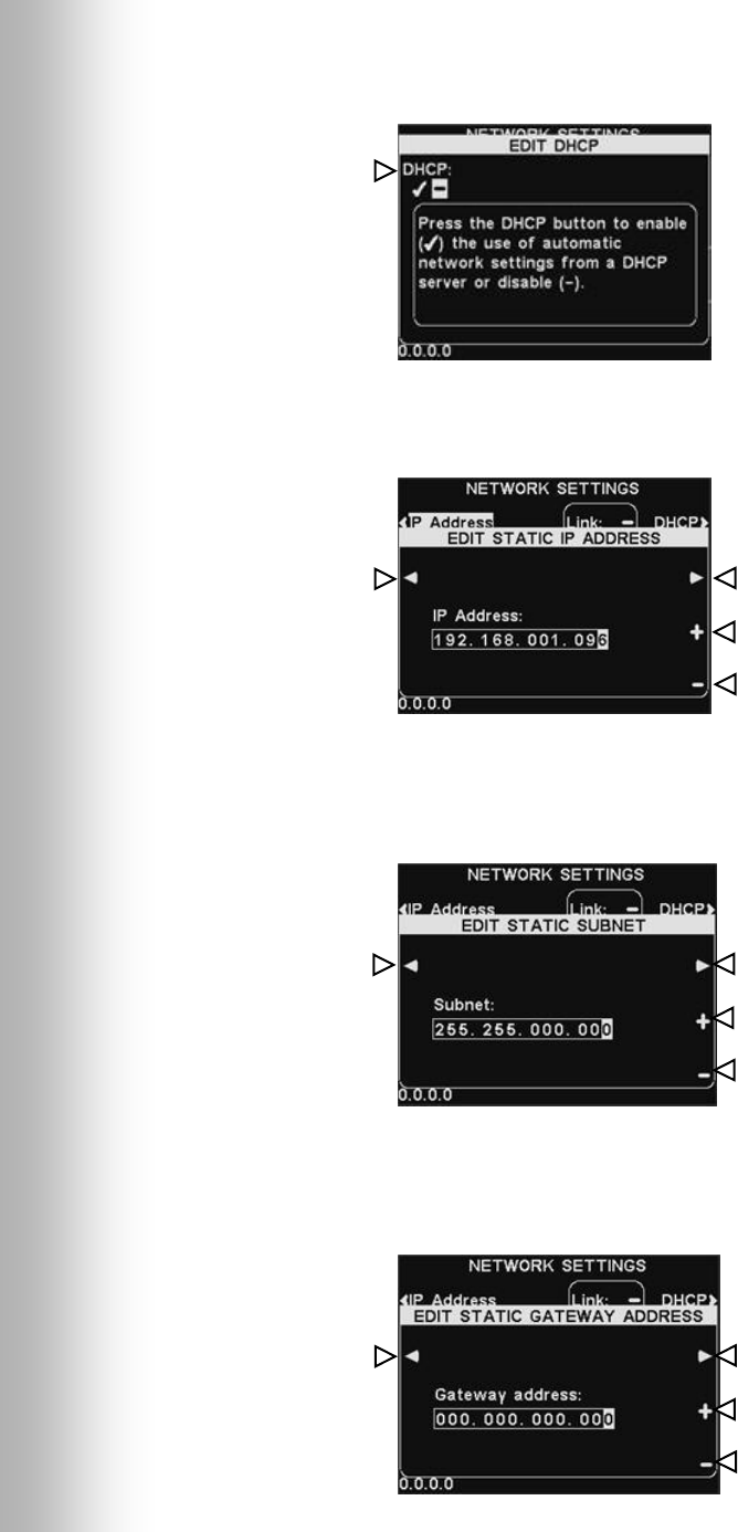
49
DHCP – allows the base to automatically acquire its network
settings from a DHCP server installed on the local network.
IP Address – the internet protocol address of the base, used to
identify the base on the local network.
Subnet – is a setting used by the base to identify if outgoing
network packets are intended for the local network or intended to
be routed to an external network via the gateway.
Gateway address – is a router address on the local network used
to move network packets from an external network into the local
network and vice-versa.
To edit this setting, press the
DHCP button to highlight ✔(on)
or −(off). If −(off) is highlighted,
the base will use static network
settings that you enter via the
NETWORK SETTINGS and
ADVANCED NETWORK
SETTINGS displays.
To edit this setting, press the
IP Address button and then,
on the EDIT STATIC IP
ADDRESS display, use the
◄ and ► buttons to move the
highlight to each number you
would like to change, and
press the + or − button to
enter the desired number.
To edit this setting, press the
Subnet button and then, on
the EDIT STATIC SUBNET
display, use the ◄ and ►
buttons to move the highlight
to each number you would
like to change, and press the
+ or − button to enter the
desired number.
To edit the Gateway address,
press the Gateway address
button and then, on the EDIT
STATIC GATEWAY ADDRESS
display, use the ◄ and ►
buttons to move the highlight
to each number you would like
to change, and press the + or −
button to enter the desired
number.

50
DNS1 & DNS2 – are addresses of domain name servers that resolve
host/domain names into IP addresses. The DNS servers are used
when sending email to a mail server identified by its name.
Static DNS – Typically, DNS addresses are automatically provided
by the DHCP server, if the DHCP is enabled and Static DNS is
disabled −(off). If Static DNS is enabled, ✔(on), it overrides the
DNS1 and DNS2 addresses supplied by the DHCP server, in favor
of the static addresses edited on these menus.
Advanced Network Settings
For additional advanced network settings, press the More button
on the NETWORK SETTINGS display.
Press the respective button on the ADVANCED NETWORK
SETTINGS display for each setting you would like to view or change.
To edit the DNS address, press
the DNS1 or DNS2 button and
then, on the EDIT DNS
ADDRESS display, use the
◄ and ► buttons to move the
highlight to each number you
would like to change, and press
the + or − button to enter the
desired number.
To enable/disable Static DNS,
press the DHCP button, and then
press the Static DNS button to
highlight ✔(on) or −(off).
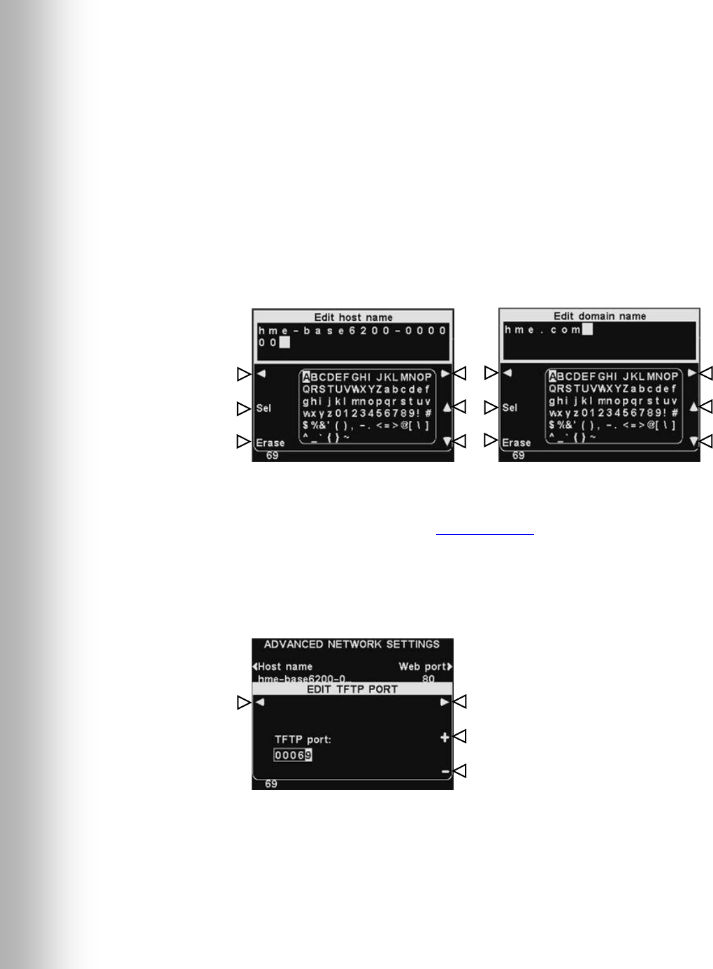
51
Host name / Domain name – These names combine to uniquely
identify the base by name, on the network. This name can be
used to access the base over the network instead of using the IP
address. This feature only works if DHCP is enabled on the
NETWORK SETTINGS display, and a DNS server is installed on
the local network, and it is configured to receive updates from the
DHCP server.
To enter or change host or domain name, press the Edit host
name or the Edit domain name button on the ADVANCED
NETWORK SETTINGS display. On the respective Edit… display,
use the Erase button to clear any characters in a current name
that you want to change. Use the ◄, ►, ▲ and ▼ buttons to move
the highlight to a character you would like to enter in the name,
and then press the Sel (select) button to enter it. When you are
finished, press the Back button to save the name.
Emails – The base is capable of sending emails to store managers
when alert conditions are triggered in the store.
For email settings, refer to Email/Texting.
TFTP port – This port is used for transferring files to the base (for
updating settings and audio files) and from the base (for reading
settings files only). The port value is 69, but can be changed if
necessary, or set at 0 to disable the port.
To edit the TFTP port
number, on the EDIT TFTP
PORT display, use the ◄
and ► button to move the
highlighted box, and then
use the + and − buttons to
change the number in the
highlighted box.
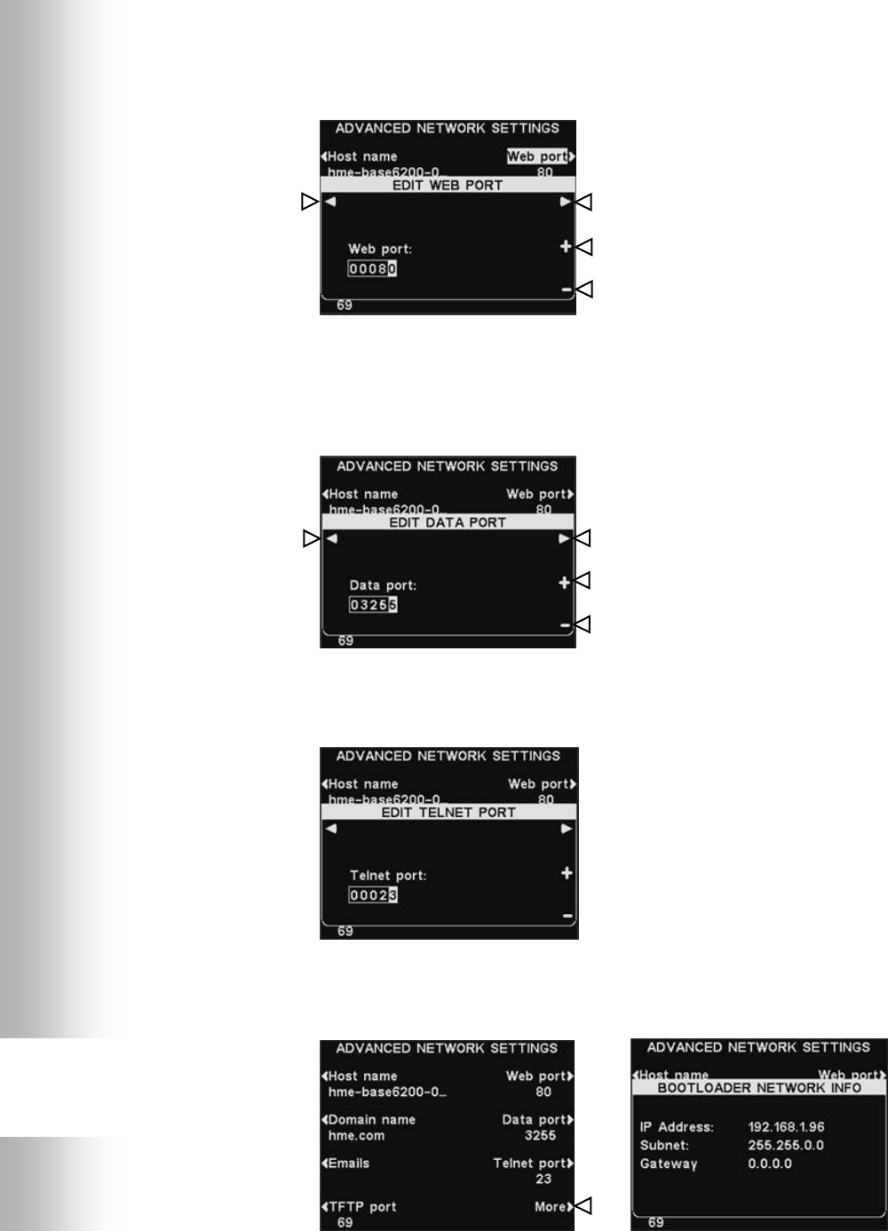
52
Web port – This port is used for web access of the bases’ web
pages, to view control settings, etc. The port value is 80, but can
be changed if necessary, or set at 0 to disable the port.
Data port – This port is used for sending HME-supported
commands to the base over a TCP/IC socket. The port value is
3255, but can be changed if necessary, or set at 0 to disable the
port.
Telnet port – This port is reserved for use by HME Technical
Support.
Press the More button on the ADVANCED NETWORK SETTINGS
display to access the BOOTLOADER NETWORK INFO display.
To edit the web port
number, on the EDIT WEB
PORT display, use the ◄
and ► button to move the
highlighted box, and then
use the + and − buttons to
change the number in the
highlighted box.
To edit the data port
number, on the EDIT DATA
PORT display, use the ◄
and ► button to move the
highlighted box, and then
use the + and − buttons to
change the number in the
highlighted box.
NOTE:
Bootloader information
is used by
HME Technical Support.
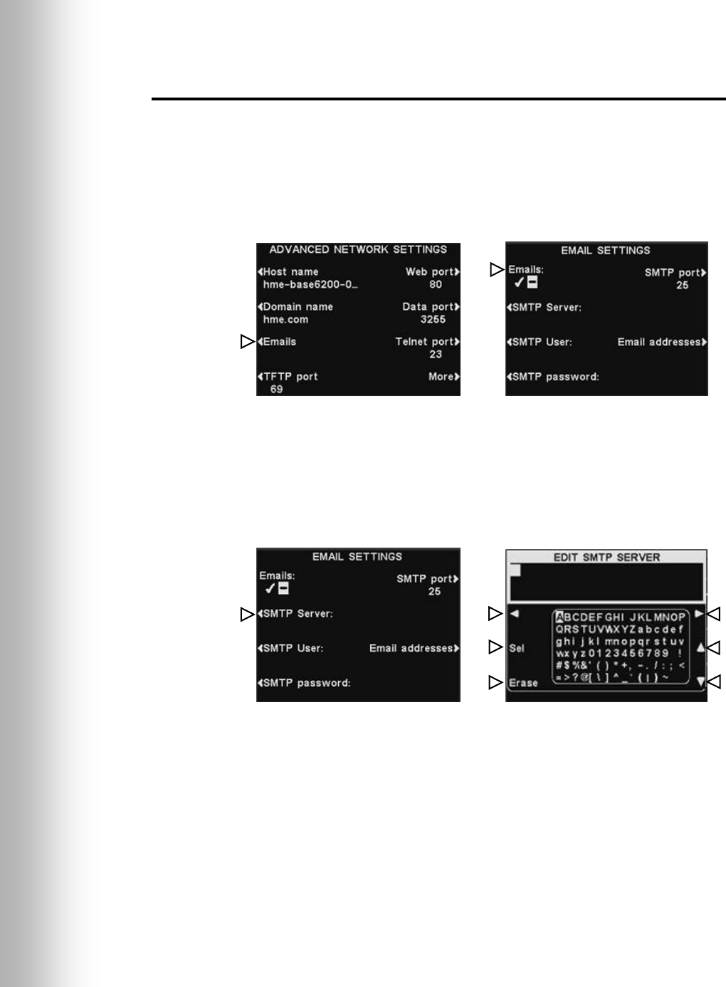
53
Email/Texting
The base is capable of sending emails to store managers when
alert conditions are triggered in the store. For this feature to be
used, email settings must be entered, based on network
information provided by your IT support.
To edit email settings, press the Emails button on the ADVANCED
NETWORK SETTINGS display.
To turn emails on or off, on the EMAIL SETTINGS display, press
the Emails button to highlight ✔(on) or −(off).
SMTP Server – This is the SMTP (mail) server which will convey
your emails to the proper email addresses. You can either enter
the IP address of the SMTP server or its domain name.
To enter or edit an SMTP server name, press the SMTP Server
button on the EMAIL SETTINGS display. Use the Erase button to
clear a current name. Use the ◄, ►, ▲ and ▼ buttons to highlight
a character you would like to enter in the name, and then press the
Sel (select) button to enter it in the highlighted box above.
When you are finished, press the Back button to save the name.
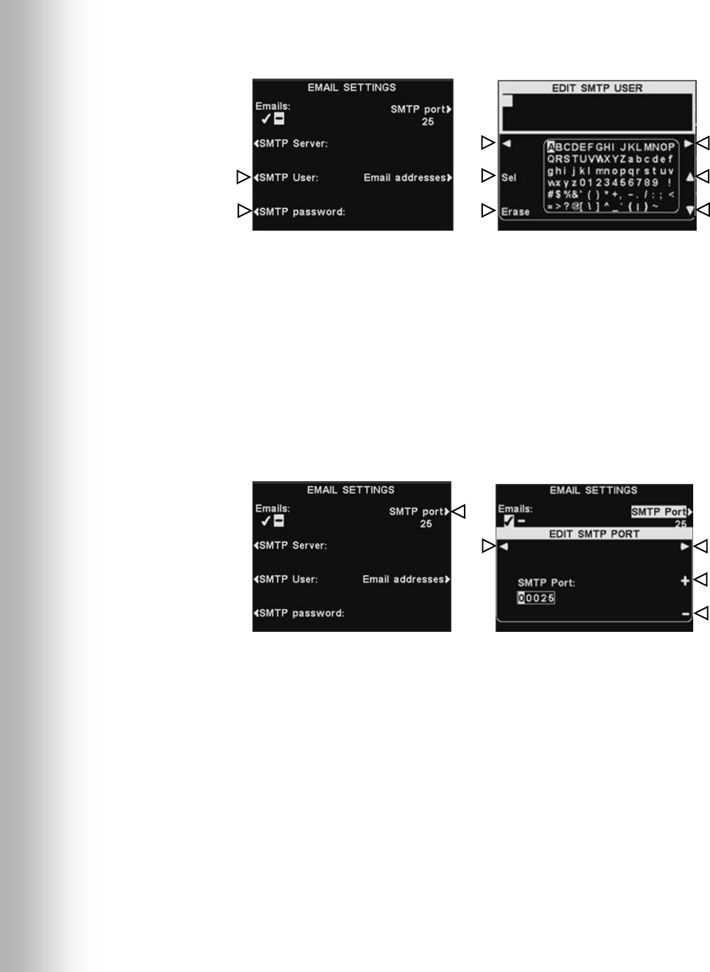
54
SMTP User/Password – To make email more secure, some SMTP
servers will require the use of a user name or password.
To enter or edit an SMTP user name or password, press the SMTP
User or Password button on the EMAIL SETTINGS display. Use
the Erase button to clear a current name. Use the ◄, ►, ▲ and ▼
buttons to highlight a character you would like to enter in the
name, and then press the Sel (select) button to enter it in the
highlighted box above. When you are finished, press the Back
button to save the name.
SMTP Port – The SMTP port is usually set to 25. However, some
mail servers use a different port. If it is necessary to change the
SMTP port number, press the SMTP Port button on the EMAIL
SETTINGS display.
To edit the SMTP port number, on the EDIT SMTP PORT display,
use the ◄ and ► button to move the highlighted box, and then
use the + and − buttons to change the number in the highlighted
box.
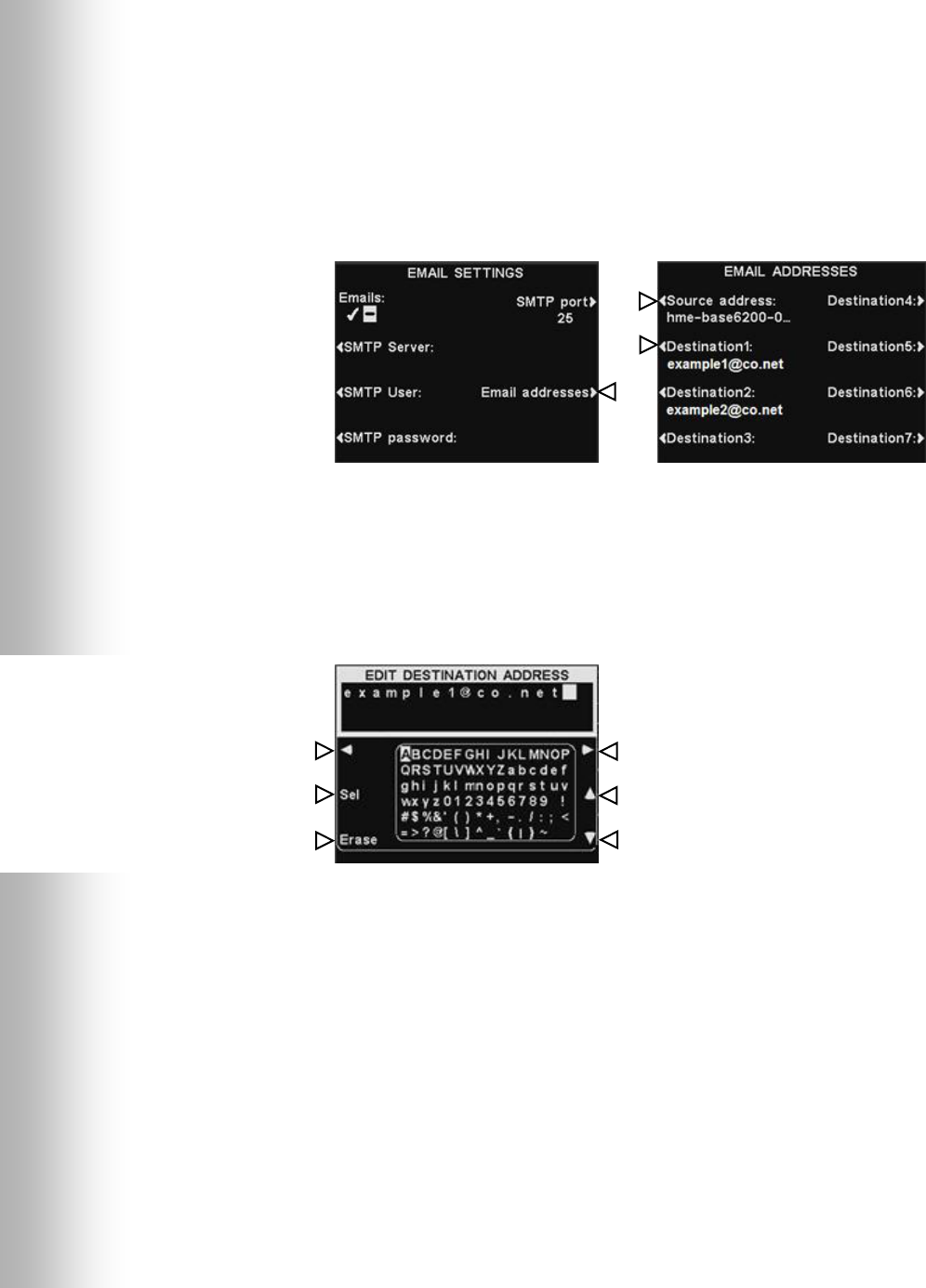
55
Email Addresses –
The Source Address is pre-set to
hme-base6200@hme.com.
This will be the address shown in the “From:” line on alert emails
sent to selected destinations. Destination email addresses are
those to which alert emails will be sent if Emails are set to ✔(on),
on the EMAIL SETTINGS display.
To change the Source Address or Destination addresses, press
the Email Addresses button on the EMAIL SETTINGS display.
To enter or edit an email address, press the Source Address or any
Destination address button on the EMAIL ADDRESSES display.
Use the Erase button to clear a current address. Use the ◄, ►, ▲
and ▼ buttons to highlight a character you would like to enter in
the address, and then press the Sel (select) button to enter it in
the highlighted box above.
When you are finished, press the Back button to save the address.
NOTE:
It is very important that
email addresses be
entered correctly.
If any email address is
entered incorrectly, the
Message Center Alert
emails will not work
properly.
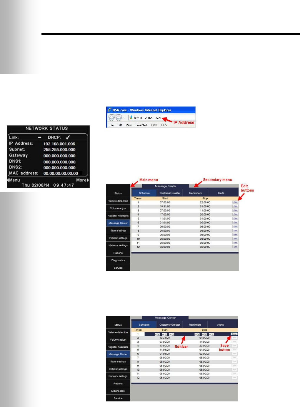
56
PC Navigation
If your EOS|HD was set up to operate with a PC network, all of the
same settings that can be edited on the base station can also be
edited on your PC. The following examples show you how to navigate
through system settings as they appear on your PC screen.
The EOS|HD provides the ability to view and edit base station
configuration settings.
To open the EOS|HD on your PC, enter its IP Address in the
address bar on your internet browser as shown below, and then
press the Enter key on your keyboard.
Select any category from the Main Menu that you would like to
view or edit. Some topics will cause a Secondary Menu bar to
appear, from which you can select a sub-topic.
If you click your cursor on an Edit button, an edit bar will appear
with setup choices. If you make any setup changes, you must
click on the Save button to save your changes. If you do not want
to save your changes, or do not make any changes, you can click
on any other menu topic, or click on the back arrow at the top-left
corner of the browser screen.
NOTE:
To find the IP Address, go
through the following
display path on your base
station: LANE STATUS>
More>More>More>More.

57
The EOS|HD interface provides the following web pages:
Status – provides Lane, Message, Base, Version, Network and
Copyright information.
Vehicle detection – allows you to control and reset the vehicle
detectors on the base.
Volume adjust – allows you to adjust audio volumes.
Register headset – allows you to register one or multiple
headsets, or to clear headset registrations.
Message Center – allows you to set up messages to be played to
audio destinations as well as in the case of Alert messages, set up
text messages to be sent to email and text recipients.
Store settings – allows you to set up store parameters such as
date, time, store hours, schedule times, passwords, B to Order
Taker, VAA, AVC, Phone headset and LCD contrast, as well as
Restore installer settings.
Installer settings – allows you to set up basic operational settings
such as Lane configuration, Auto-Hands-Free, Language selection,
Speaker post configuration, ClearSound, Phone, Line In/Out
routing, Radio options and Vehicle tone, as well as Save installer
settings and Restore factory settings.
Reports – allows you to view Message Center settings and headset
statistics reports.
Diagnostics – provides information that may be used by HME
Technical Support to diagnose problems.
Service – displays all version information and contact information,
in case you need assistance from HME Technical Support.

58
EQUIPMENT CARE AND CLEANING
Handling the Equipment Properly
When adjusting the position of the headset microphone, hold the
boom at its base, not at the microphone end.
Carry the headset by the headband, not by the earpiece, and never
by the microphone boom.
Use both hands to put the headset on or take it off.
Cleaning the Equipment
Headsets
Remove the battery.
Clean the battery and headset with a damp sponge sprayed with
household cleaner. Squeeze excess liquid out of the sponge before
using it.
Clean the metal battery contacts on the battery and headset as
follows. Wet the tip of a swab with alcohol and squeeze the excess
alcohol from it. Wipe each contact with the swab and be certain
all the contacts are dry before reinstalling the batteries.
Foam muffs on headset earpieces can easily be replaced for
sanitary purposes. To order extra foam muffs, call your local HME
sales representative.
Battery Charger
Avoid splashing water or grease on the battery charger.
Clean the battery charger monthly as follows.
Remove all batteries from the battery charger.
Clean the battery charger case with a damp sponge. Wet the
sponge and wring it out so it is damp, not dripping wet. Spray
household cleaner on the sponge (NOT DIRECTLY ON THE
EQUIPMENT). Clean the battery charger with the sponge and dry
it thoroughly.
Wet the tip of a cotton swab with rubbing alcohol and squeeze the
excess alcohol from the swab. Wipe the metal contacts inside each
battery port with the damp swab. Allow the contacts to dry before
placing batteries in the ports.
CAUTION:
Always unplug
the battery
charger before
cleaning it.

59
IN CASE OF PROBLEMS
Troubleshooting
PROBLEM
PROBABLE CAUSE
SOLUTION
“Battery failed” is heard
in headset when power
button is pressed.
Battery may be defective.
Replace battery. Call HME.*
Battery contacts may be dirty.
Clean battery contacts with alcohol.
“Headset failed” is
heard in headset when
power button is pressed.
Headset may be defective.
Use another headset. Call HME.*
Headset battery contacts may be dirty.
Clean headset battery contacts with alcohol.
You hear your echo in
headset earpiece when
you speak into headset
microphone.
Outside speaker and microphone may
not be properly installed.
Be sure speaker and microphone are isolated from each
other, and are tightly mounted with enough foam packed
around each of them to absorb vibrations.
Outbound and/or inbound audio level
may be set too high.
Set outbound audio level just high enough to be heard by
customers. Lower inbound audio to comfortable level.
VAA level may need to be adjusted.
Adjust VAA level to reduce inbound audio level when you
are speaking into the headset microphone.
Adjust VAA attenuation level to reduce inbound audio level
when you are speaking into the headset microphone.
NOTE: If the inbound level is too low, you will not hear
the customer.
No sound is heard in
headset when you press
button A and speak into
microphone.
Power may be off at base station.
Be sure HME logo and other lights on base station are lit.
Check circuit breaker for building.
Power supply in base station may not be
working.
Be certain power adapter is plugged into AC electrical outlet,
and is connected to J3 on base station audio circuit board.
Headset power may not be on.
Press power button on headset. Be certain power light goes
on and switches from red to green.
Volume may not be set correctly.
Adjust volume with Volume-up and down buttons.
Battery may be low or defective.
Check Power light. If not lit, replace battery.
Headset may be defective.
Use another headset. Call HME.*
Headset may not be registered.
Register headset.
Channel A or B is not
working.
Headset power may not be on.
Press power button on headset. Be certain power light goes
on and switches from red to green.
Battery may be low or defective.
Check Power light. If not lit, replace battery.
A1/A2 or B1/B2 light on base station
does not light when headset button A or
B is pressed.
Use another headset. Call HME.*
Headset may not be registered.
Register headset.
Outbound sound is too
low.
Outbound volume may be set too low for
environment.
Adjust outside speaker volume level.
No outbound sound;
Customer cannot hear
anything.
System may be set for speed team.
Check speed-team setting.
There may be loose wires on outside
speaker or base station circuit board.
Check vehicle present light (car) on base station.
Check outside speaker wire connections on J6 or J14 in base
station and at outside speaker.
Defective speaker or base station.
Call HME.*

60
PROBLEM
PROBABLE CAUSE
SOLUTION
Customer cannot be
heard in push-to-talk
(PTT) operation.
System may be set for speed team.
Check speed-team setting.
Base station may be set for wrong drive-
thru mode (full or half-duplex).
Check drive-thru mode setting.
Only intermittent voice
can be heard in
headsets.
Transmitter antenna connectors on base
station transceiver circuit board may be
loose or damaged.
Be certain antennas are screwed securely onto base station.
Check transmitter antenna cable connection at ANT1 and
ANT2 on left side of transceiver circuit board. Call HME.*
Circuit board may be defective.
Call HME.*
VAA level is too sensitive.
Reduce VAA level.
Personnel hear
customers in ceiling
speaker or headsets, but
cannot hear each other.
Circuit board may be defective.
Check to see if A1/A2 and B1/B2 lights on base station are
lit when buttons are pressed. Call HME.*
Headset may be defective.
Use another headset. Call HME.*
No tone or sound is
heard in ceiling speaker
or headsets when vehicle
enters drive-thru lane.
Power interruption may have caused
vehicle detection circuit to be out of
balance.
When no vehicle is in the drive-thru lane, reset vehicle
detector.
System may be set for speed team.
Check speed-team setting.
Connector may be loose.
Check all connectors in base station. Call HME.*
Personnel cannot hear
customers in ceiling
speaker or headsets.
There may be loose wires on base station
circuit board.
Check all wire insertions to connectors on base station circuit
boards.
System may be set for speed team.
Check speed-team setting.
Outside speaker, audio circuit board or
vehicle detector board failed.
Call HME.*
VAA attenuation set too high.
Reduce attenuation.
Headset has intermittent
sound.
Battery may be low.
Replace battery.
Headset may be defective.
Use another headset. Call HME.*
There is still sound in
headset after all
customers have been
served.
Base station may be to override position.
On the VEHICLE DETECTION menu, be certain the Mode
setting is in the Normal position.
Vehicle detector may be locked up.
On the VEHICLE DETECTION menu, select Reset Veh
Detect.
Battery charger is not
working.
Charger may not be plugged in.
Be certain charger is plugged in.
If it still is not working, call HME.*
“Registration failed”
message heard in
headset. Lights stay
red.
Base station power not on.
Be sure HME logo and other lights on base station are lit. If
no light is lit, be sure power adapter is plugged into electrical
outlet, and is connected to J3 on base station audio circuit
board.
Registration button not pushed.
Repeat registration procedure. Call HME.*
Service Call
For information to contact HME Technical Support, press the Menu button on the base
station LANE STATUS display and then press the Service button on the MAIN MENU, or
press the Help button below the display screen.
*

61
Base Station Internal Connectors and Controls
ANT1 antenna connector
ANT2 antenna connector
Switcher board connectors, J4-Lane 1
Switcher board connectors, J13-Lane 2
Ethernet connector, J12
Power connector, J3
Ceiling speaker connector, J1-Lane 1, J11-Lane 2
Outside speaker/microphone connector, J6-Lane 1, J14-Lane 2
Line in/out connector, J7-Lane 1, J16-Lane 2
Early warning/alert connector, J9-Lane 1, J19-Lane 2
Remote switch connector, J2
Reset switch
Telephone connector, J15
Doors connector, J5
Vehicle detector board (VDB) connector, J10-Lane 1, J20-Lane 2
Figure 9. Base station internal connectors and controls
1 2
11
12
13
14
15
3 4 5 6 7 8 9 10
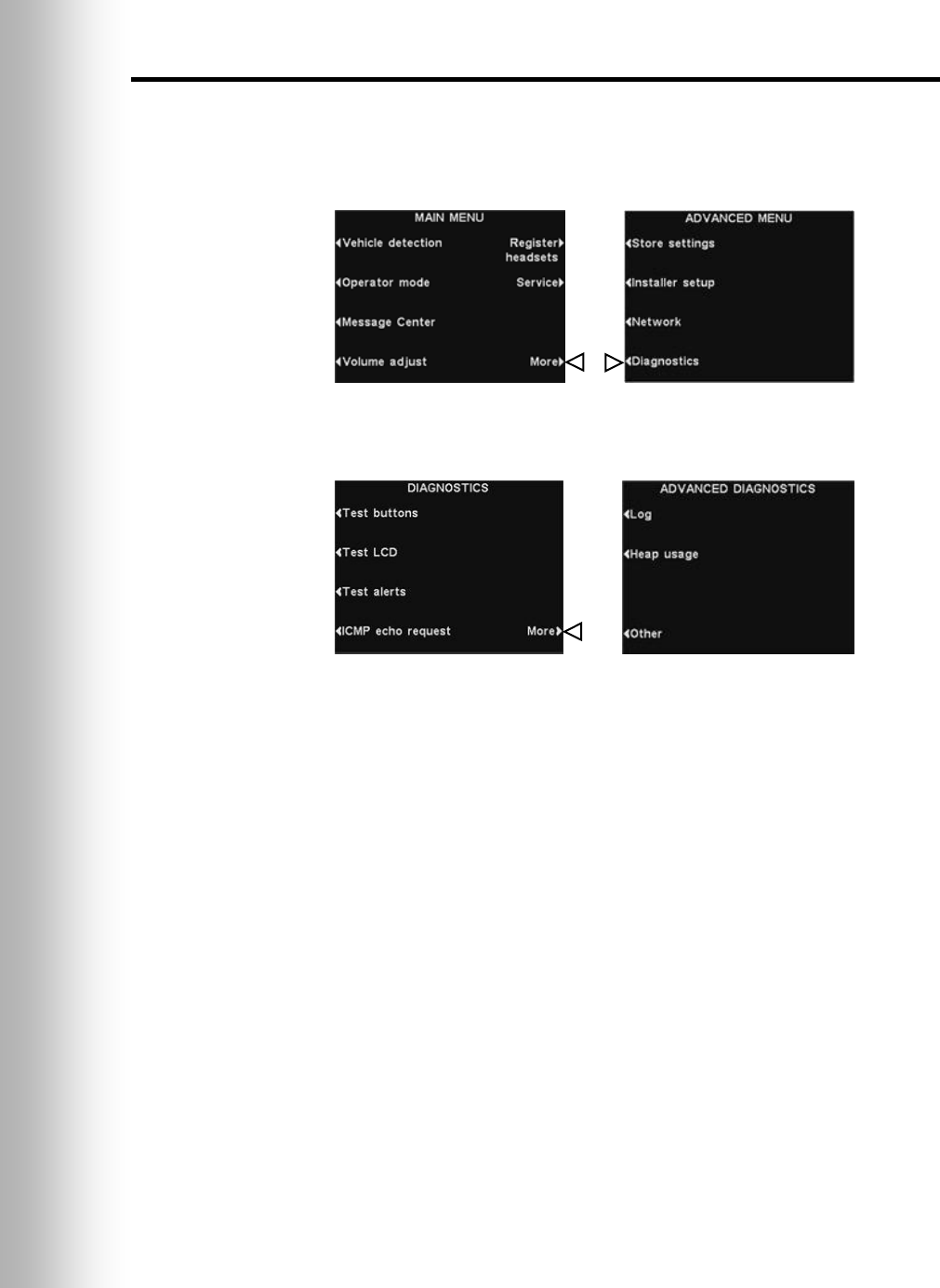
62
Diagnostics
If you make a service call to HME Technical Support, you may be
asked to have diagnostics performed automatically by the base
station. If so, press the Menu button on the base station LANE
STATUS display and then press the More button on the MAIN
MENU.
On the ADVANCED MENU, press the Diagnostics button, and
then select the test requested by the Technical Support
representative. If requested, press the More button for additional
advanced diagnostics.

63
EQUIPMENT SPECIFICATIONS
Base Station
Voltage input 24VDC ±2.5V
DC current input 2.5A maximum
Audio distortion 5% maximum level
Outside speaker output 3 watts RMS into 8 ohms
Ceiling speaker power 3 watts RMS into 8 ohms
TX/RX frequency 2400MHz – 2483.5MHz
Dimensions 9.75”H x 13”W x 3.5”D
(248 mm x 330 mm x 89 mm)
Weight 3.25 lbs (1.47 kg) maximum
Headset
Battery type 3.6V Lithium ion
Battery life 11 - 13 hours (typical)
RF frequency 2400MHz – 2483.5MHz
Weight 3.53 oz (100 gm) with battery
Battery Charger
Voltage input 16.5VAC
Charging time 2.5 hrs maximum
Dimensions 5.56” x 4.25” x 1.69”
(141 mm x 108 mm x 43 mm)
Weight 12.03 oz (341 gm) with bracket

64
IMPORTANT NOTICES
FCC Regulation
This device complies with Part 15 of the FCC rules. Operation is subject to the following two conditions:
(1) This device may not cause harmful interference, and (2) This device must accept any interference
received, including interference that may cause undesired operation.
NOTE: This equipment has been tested and found to comply with the limits for a Class A digital device,
pursuant to Part 15 of the FCC rules. These limits are designed to provide reasonable protection against
harmful interference when the equipment is operated in a commercial environment. This equipment
generates, uses and can radiate radio frequency energy and, if not installed and used in accordance with
the instruction manual, may cause harmful interference to radio communication. Operation of this
equipment in a residential area is likely to cause harmful interference, in which case the user will be
required to correct the interference at his own expense.
Changes or modifications not expressly approved by HM Electronics, Inc. could void the users authority
to operate this equipment.
The antenna(s) used for the base transmitter must be installed to provide a separation distance of at least 7.87
inches (20 cm) from all persons, and must not be co-located or operating in conjunction with any other
antenna or transmitter.
This device has been designed to operate with the antennas or antenna kits listed below, and having a
maximum gain of 2dBi. Antennas/Kits not included in this list or having a gain greater than 2dBi are strictly
prohibited for use with this device. The required antenna impedance is 50 ohms.
1. Antenna: NEARSON, S181TR-2450R, 2dBi
2. Antenna Kit: HME, EC20 (P/N G28493-1), 0dBi
3. Antenna Kit: HME, EC10 (P/N G27706-1)
Industry Canada (IC)
This device complies with Industry Canada license exempt RSS standard(s). Operation is subject to the
following two conditions: (1) this device may not cause interference, and (2) this device must accept any
interference received, including interference that may cause undesired operation of the device.
This device complies with Health Canada’s Safety Code. The installer of this device should ensure that
RF radiation is not emitted in excess of the Health Canada’s requirement. Information can be obtained at
http://www.hc-sc.gc.ca/ewh-sem/pubs/radiation/radio_guide-lignes_direct-eng.php
“Changes or modifications not expressly approved by the party responsible for compliance could void the
user’s authority to operate the equipment.”
Hereby, HM Electronics, Inc. declares that the EOS|HD is in compliance with the essential
requirements and other relevant provisions of R&TTE Directive 1999/5/EC.
Waste Electrical and Electronic Equipment (WEEE)
The European Union (EU) WEEE Directive (2002/96/EC) places an obligation on producers
(manufacturers, distributors and/or retailers) to take-back electronic products at the end of their useful
life. The WEEE Directive covers most HME products being sold into the EU as of August 13, 2005.
Manufacturers, distributors and retailers are obliged to finance the costs of recovery from municipal
collection points, reuse, and recycling of specified percentages per the WEEE requirements.
Instructions for Disposal of WEEE by Users in the European Union
The symbol shown below is on the product or on its packaging which indicates that this product was put
on the market after August 13, 2005 and must not be disposed of with other waste. Instead, it is the
user’s responsibility to dispose of the user’s waste equipment by handing it over to a designated collection
point for the recycling of WEEE. The separate collection and recycling of waste equipment at the time of
disposal will help to conserve natural resources and ensure that it is recycled in a manner that protects
human health and the environment. For more information about where you can drop off your waste
equipment for recycling, please contact your local authority, your household waste disposal service or the
seller from whom you purchased the product.

65
Regulatory Model Numbers
The EOS|HD Base Station, BASE6200, has a Regulatory Model Number of 1401.
The EOS|HD Headset, HS6200, has a Regulatory Model Number of 1402.
The EOS|HD Beltpac, COM6200, has a Regulatory Model Number of 1403.
Brazil
“Este produto está homologado pela ANATEL, de acordo com os procedimentos regulamentados pela Resolução 242/2000, e
atende aos requisitos técnicos aplicados” Para maiores informações, consulte o site da ANATEL www.anatel.gov.br
China BASE6200 (1401) Regulatory ID number — CMIIT ID: 2014DJ4271
HS6200 (1402) Regulatory ID number — CMIIT ID: 2014DJ4272
Indonesia BASE6200 (1401) Regulatory ID number — 37991/SDPPI/2014 3710
HS6200 (1402) Regulatory ID number — 38040/SDPPI/2014 3710
Korea 해당 무선설비는 전파혼신 가능성이 있으므로 인명안전과 관련된 서비스는 할 수 없음 이 기기는
업무용(A급)으로 전자파적합기기로서 판매자 또는 사용자는 이 점을 주의하시기바라며, 가정외의
지역에서 사용하는 것을 목적으로 합니다.
Russia BASE6200 (1401) Regulatory ID number — RU C-US.ME06.B.01386
HS6200 (1402) Regulatory ID number — RU C-US.ME06.B.01387
Taiwan 注意!
依據低功率電波輻射性電機管理辦法第十二條經型式認證合格之低功率射頻電機,非經許可,
公司、商號或使用者均不得擅自變更頻率、加大功率或變更原設計之特性及功。
第十四條低功率射頻電機之使用不得影響飛航安全及干擾合法通信;經發現有干擾現象時,
應立即停用,並改善至無干擾時方得繼續使用。前項合法通信,指依電信規定作業之無線電信。
低功率射頻電機須忍受合法通信或工業、科學及醫療用電波輻射性電機設備之干擾。
Thailand This telecommunication equipment conforms to NTC technical requirements.
UAE

66
APPENDIX
Multiple-Lane Operation
Dedicated Mode
In multiple-lane operations only, an Activate dedicated mode setting appears
on the OPERATOR MODE display. In the dedicated mode, headset users only
hear vehicle arrival tones and audio for their own lane.
To set up dedicated mode operation, select Menu on the LANE STATUS display
and then select Operator mode on the MAIN MENU.
On the OPERATOR MODE display, press the Activate dedicated mode button
to select ✔(on). When you want to return to normal operation, you must select
−(off). Press the Dedicated HELP button for additional explanation.

67
Multiple-Lane Message Center Settings
Customer Greeter Messages
In multiple-lane operations, Customer Greeter messages can be set to play in
Lane 1, Lane 2, or both Lanes 1 & 2. To do this, press the Edit button on the
CUSTOMEER GREETER display, and then press the Event button to highlight
Lane 1, Lane 2 or Lane 1/2.
Reminder Messages
In multiple-lane operations, Reminder messages can be set to play in the ceiling
speaker and Line Out for Lane 1, Lane 2, or both Lanes 1 & 2. To do this, press
the Settings button on the EDIT REMINDER MESSAGE display and the, on the
EDIT REMINDER SETTINGS display, press the Hear in ceiling speaker and
Hear in Line Out buttons to highlight Lane 1, Lane 2 or Lane 1/2.
Alert Messages
In multiple-lane operations, Alert messages can be set to play in the ceiling
speaker and Line Out for Lane 1, Lane 2, or both Lanes 1 & 2. To do this, press
the Settings button on the EDIT ALERT MESSAGE display and the, on the
EDIT ALERT SETTINGS display, press the Hear in ceiling speaker and Hear
in Line Out buttons to highlight Lane 1, Lane 2 or Lane 1/2.

68
Access Control of EOS|HD Menus
The EOS|HD menus are designed to be easily accessible by store personnel, but
can be protected by a USER PASSWORD to prevent unauthorized changes.
Store settings menus, Network settings menu, Message Center menus and
Volume adjustment menus can be protected if a User Password is created in
the Store Settings. These menus can be accessed using the User Password
(provided by HME if the User Password is forgotten).
When the password has been entered to access a menu, it will no longer be
required to access other protected menus, as long as there is menu activity.
After 5 minutes of no menu activity, the password will again be required to
enter the protected menus. This also applies to protected web pages.
Password required
Menus
None
Status screens
Detector menus (Speed team, Reset vehicle detectors)
Registration menus
Diagnostics menus
Service screen
User password
Store settings menus
Network settings menus
Message Center menus
Volume adjustment menus
If a password is required, you will see one of the following displays.
To enter a password, use the ◄ and ► buttons to move the highlighted box left
and right in the Enter Password field, and use the + button to put alphabetic
characters in the box, or the − button to put numeric characters in the box. Each
time you have entered a character of your password, press the ► button to move
the highlighted box to the next position and enter the next character. If you want
to start over with a new password, press the Clear all button. After entering your
entire password, press the Continue button.
NOTE:
Some settings are
protected by an
Installer Password
that is available
only to the
installer or other
HME-authorized
personnel.
HME EOS|HD Message Center Quick Start Guide
Right Message, Right People, Right Time!
INSTRUCTIONS
Planning to set-up your HME EOS|HD Message Center is easy to do when you follow these three simple steps.
STEP ONE: Choose your CUSTOMER GREETINGS, EMPLOYEE REMINDERS, and ALERTS
TIP: Schedule only a few messages at a time and change them often to improve your customers’ and
employees’ awareness. Choose from several common messages provided in your HME EOS|HD, or record your
own unique messages. (See Page 16 in your EOS|HD Operating Instructions manual for a list of pre-
programmed messages.)
3 or 4 CUSTOMER GREETINGS that play to your customers when they arrive at the menu board
2 or 3 REMINDERS that play to your employees to remind them of important tasks such as hand washing
1 or 2 ALERTS that notify the employees when something needs immediate attention such as when the
back door is left open
STEP TWO: Determine WHEN and WHERE the messages play
CUSTOMER GREETINGS play through the speaker at the menu board, and the headsets and ceiling
speakers. REMINDERS and ALERTS are played through any or all headsets and/or grill speaker. Playing
REMINDER and ALERT messages to ALL headsets is the default setting and is most commonly used
A REPEAT interval can be set if you want a REMINDER to be played throughout the day. For example, set
the repeat interval for 60 minutes, the task reminder of hand washing will play every 60 minutes.
A DELAY can be set for an ALERT when you want to be notified if something has occurred for a specific
period of time. For example, set the delay to ALERT you when the back door has been left open for five
minutes.
STEP THREE: Create your message schedule for the messages listed in STEP TWO
CUSTOMER GREETINGS can be scheduled to change with your day-part business. For example, schedule
one greeting for breakfast, another for lunch and dinner, and a third to promote an all-day special.
TIP: A default STORE CLOSED message can play automatically to cars that arrive after the store is closed, and
stop playing when the store opens. To use this feature, you must make sure the store hours are set correctly.
(See page 41 in your EOS|HD Operating Instructions manual.)
REMINDERS and ALERTS are commonly scheduled to play ALL DAY and typically use the delay or repeat
feature
The message SCHEDULE can be customized by day, although it is most commonly the same for every day
of the week
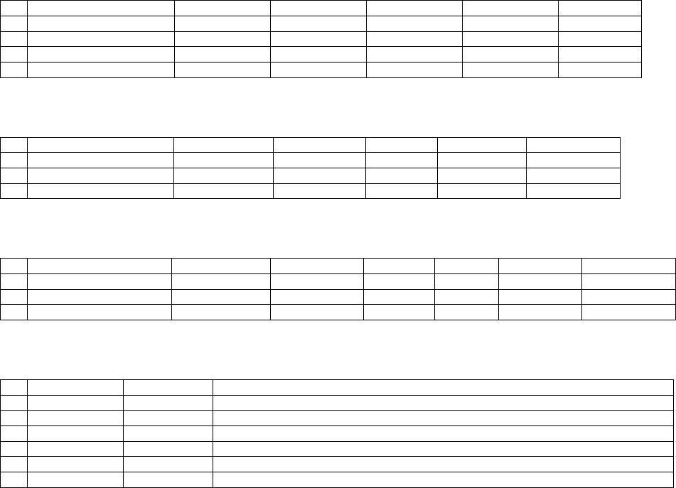
HME EOS|HD Message Center Quick Start Guide
Right Message, Right People, Right Time!
EXAMPLE PLANNER
CUSTOMER GREETINGS
NAME
START TIME
STOP TIME
HEADSETS
CEILING SPKR
DELAY
1
BREAKFAST
06:00
11:00
✔(on)
✔(on)
03
2
LUNCH/DINNER
11:00
20:00
−
(off)
−
(off)
00
3
DRINK PROMO
06:00
01:00
✔(on)
✔(on)
05
4
REMINDERS
NAME
START TIME
STOP TIME
REPEAT
HEADSETS
CEILING SPKR
1
HAND WASHING
06:00
01:00
1 Hr
ALL
YES
2
CHANGE SANITIZER
06:00
01:00
4 Hr
ALL
YES
3
ALERTS
NAME
START TIME
STOP TIME
REPEAT
DELAY
HEADSETS
CEILING SPKR
1
BACK DOOR DAY
06:00
01:00
5 min
5 min
ALL
YES
2
BACK DOOR NIGHT
20:00
01:00
5 min
1 min
ALL
YES
3
SCHEDULE
START TIME
STOP TIME
NOTES
1
06:00
11:00 am
Customer Greeting #1
2
11:00
20:00 pm
Customer Greeting #2
3
06:00
01:00 am
Customer Greeting #3, Reminder #1 and #2
4
06:00
20:00 am
Alert #1
5
20:00
01:00 am
Alert #2
6
NOTE: You can set up to 12 different time schedules.

HME EOS|HD Message Center Quick Start Guide
Right Message, Right People, Right Time!
CUSTOMER GREETINGS
NAME
START TIME
STOP TIME
DELAY
HEADSETS
CEILING SPKR
1
2
3
4
5
6
7
8
9
10
REMINDERS
NAME
START TIME
STOP TIME
REPEAT
HEADSETS
CEILING SPKR
1
2
3
4
5
6
7
8
9
10
ALERTS
NAME
START TIME
STOP TIME
REPEAT
DELAY
HEADSETS
CEILING SPKR
1
2
3
4
SCHEDULE
START TIME
STOP TIME
NOTES
1
2
3
4
5
6
7
8
9
10
11
12
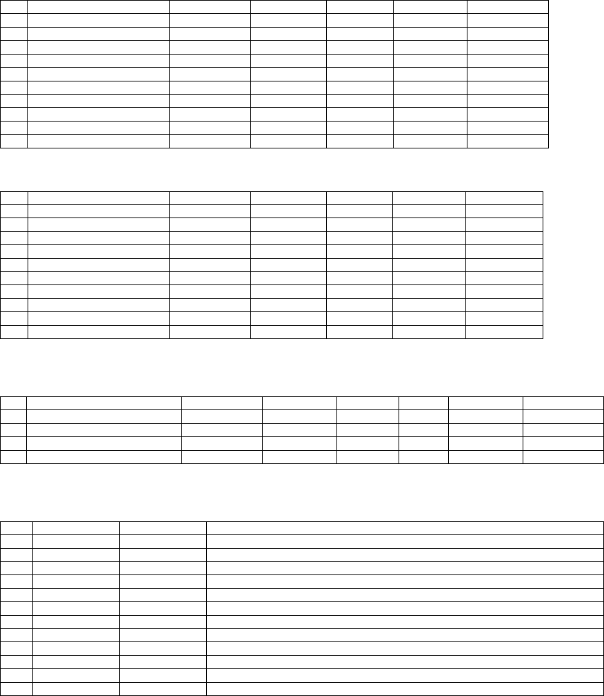

HME EOS|HD Message Center Quick Start Guide
Right Message, Right People, Right Time!
CUSTOMER GREETINGS
NAME
START TIME
STOP TIME
DELAY
HEADSETS
GRILL SPKR
1
2
3
4
5
6
7
8
9
10
REMINDERS
NAME
START TIME
STOP TIME
REPEAT
HEADSETS
GRILL SPKR
1
2
3
4
5
6
7
8
9
10
ALERTS
NAME
START TIME
STOP TIME
REPEAT
DELAY
HEADSETS
GRILL SPKR
1
2
3
4
SCHEDULE
START TIME
STOP TIME
NOTES
1
2
3
4
5
6
7
8
9
10
11
12
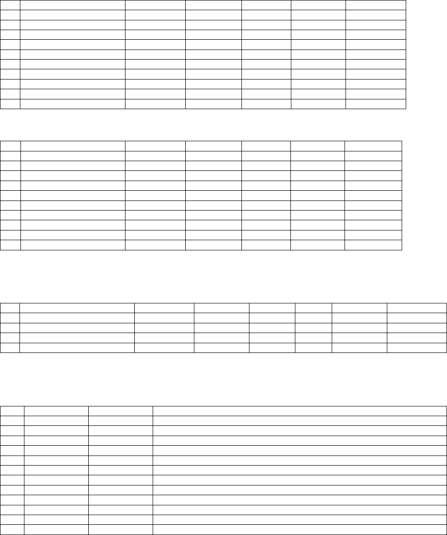
HME EOS|HD Message Center Quick Start Guide
Right Message, Right People, Right Time!
CUSTOMER GREETINGS
NAME
START TIME
STOP TIME
DELAY
HEADSETS
GRILL SPKR
1
2
3
4
5
6
7
8
9
10
REMINDERS
NAME
START TIME
STOP TIME
REPEAT
HEADSETS
GRILL SPKR
1
2
3
4
5
6
7
8
9
10
ALERTS
NAME
START TIME
STOP TIME
REPEAT
DELAY
HEADSETS
GRILL SPKR
1
2
3
4
SCHEDULE
START TIME
STOP TIME
NOTES
1
2
3
4
5
6
7
8
9
10
11
12
