
``
CORPORATE
HEADQUARTERS
Great Lakes Region, U.S.A.
TECHNICAL REPORT 1
M. JULIA HAVERTY
STRUCTURAL OPTION
ADVISOR: H. SUSTERSIC
12 SEPTEMBER 2014

CORPORATE HEADQUARTERS
M. JULIA HAVERTY | STRUCTURAL OPTION
TECHNICAL REPORT 1 1
Contents
Executive Summary ....................................................................................................................................................... 2
Purpose and Scope ........................................................................................................................................................ 3
General Description of Building ..................................................................................................................................... 4
Structural Overview ....................................................................................................................................................... 5
Brief Description of the Structural System ............................................................................................................... 5
Building Materials ..................................................................................................................................................... 5
Foundation System ................................................................................................................................................... 6
Floor System .............................................................................................................................................................. 9
Typical Floor Bay .................................................................................................................................................... 9
Framing System ....................................................................................................................................................... 11
Lateral System ......................................................................................................................................................... 12
Column Splices ..................................................................................................................................................... 13
Floor to Curtain Wall Connection ........................................................................................................................ 14
Moment Connection to Columns ........................................................................................................................ 15
Design Codes and Standards ....................................................................................................................................... 16
Design Loads ................................................................................................................................................................ 17
National Code for Live Loads and Lateral Loadings ............................................................................................... 17
Gravity Loads ........................................................................................................................................................... 17
Live Loads: ........................................................................................................................................................... 17
Dead Loads: ......................................................................................................................................................... 18
Snow Loads.............................................................................................................................................................. 18
Lateral Loads ........................................................................................................................................................... 18
Wind Loads: ......................................................................................................................................................... 18
Seismic Loads: ...................................................................................................................................................... 19
Soil Loads ................................................................................................................................................................. 19
Load Paths ................................................................................................................................................................... 20
Gravity Load Path .................................................................................................................................................... 20
Lateral Load Path .................................................................................................................................................... 20
Conclusion ................................................................................................................................................................... 21
Appendices .................................................................................................................................................................. 22
Appendix A: ............................................................................................................................................................. 22
Appendix B: ............................................................................................................................................................. 26

CORPORATE HEADQUARTERS
M. JULIA HAVERTY | STRUCTURAL OPTION
TECHNICAL REPORT 1 2
Executive Summary
The Corporate Headquarters, located in the Great Lakes Region of the United States, is a
new 5 story office and retail space designed to serve as new home base for an established and
successful US based company. The building's architecture was designed to mirror its
surrounding buildings, namely, the newer retail area situated directly to the north of the
building. In keeping with that building style, the Corporate Headquarters features a façade of
glass and face brick, construction crews broke ground on the roughly 660,000 SF building in
August 2014 and have a projected completion date of Spring 2016.
A challenge in the design of the Corporate Headquarters is the poor existing soil
conditions on part of the site. To remedy this problem, aggregate piers will be pushed down
below foundation level for the column spread footings and piers to sit upon. In addition to the
spread footings, a large portion of the building’s foundation features slab on grade and a few
grade beams.
The floor system in floors 2-5 is a composite floor framing structure consisting of metal
deck on top of steel wide flange members. Average bays are rectangular and have slight
variation in size although average sizes are around 38’ and beams typically span 40’. The
primary lateral system of the building is HSS braced frames near the building’s core.
The primary loading conditions considered in the design of this structure were live
loads, dead loads, snow loads, wind loads, seismic loads, and soil loads. To consider these
loading conditions, the 2011 Ohio Building Code was set as primary design criteria. 2011 Ohio
Building Code adopts IBC 2009, which references ASCE 7-05.
The following report will provide further information on these topics. Due to security
reasons, location maps are not currently permitted. Further consultation with the owner to
follow for subsequent technical reports.

CORPORATE HEADQUARTERS
M. JULIA HAVERTY | STRUCTURAL OPTION
TECHNICAL REPORT 1 3
Purpose and Scope
The purpose of this technical report is to describe the existing structural conditions of
the Corporate Headquarters, located in the Great Lakes Region of the Midwestern United
States.
The scope of this technical report includes descriptions of structural systems, building
materials, applicable building design codes, design loads, and load paths. This report will focus
primarily on a detailed description of the building’s structural system. This includes descriptions
of the foundation, floor system, lateral system, and roof system. Within the foundation system
description, soil conditions will also be discussed.
A full structural analysis of the design of the Corporate Headquarters will be provided in
subsequent technical reports.

CORPORATE HEADQUARTERS
M. JULIA HAVERTY | STRUCTURAL OPTION
TECHNICAL REPORT 1 4
General Description of Building
The Corporate Headquarters will be constructed at the South end of an existing retail
park in the Great Lakes Region of the Midwestern United States. It is a five story office a retail
space designed to serve as the new headquarters for an established and successful US based
company. The new 659,000 SF building’s architecture was designed to blend in with the style of
the surrounding buildings in the retail park. Designed in the contemporary “Americana” style,
the Corporate Headquarters will serve as the last component of the retail area and aims to
become the cornerstone of an already thriving community. Ground was broken on the
Corporate Headquarters in August 2014 and the project’s projected completion date is Spring
2016.
The building features an interior courtyard which begins on the third level of the
building and allows workers within the offices to bring the outside in. Additionally, this grassy
courtyard is meant to help enrich the sense of creativity and community within employees. To
achieve this courtyard, the structural design engineer chose to utilize grade beams and braced
frames, as well as aggregate piers below the foundation to help beef up the poor soil
conditions.
The Corporate Headquarters serves as the south port of entry into a retail plaza and will
incorporate retail space on its ground floor. The upper levels are dedicated to larger open
office spaces that allow for spatial transitions and mobility. Pending acquisition of land adjacent
to the site, a bridge will connect the upper floors of the Corporate Headquarters with a parking
structure, as is commonplace in the rest of the retail park. The proposed face brick and curtain
wall façade mimics the “Main Street America” feel of the retail park but speaks to how the
company has evolved throughout the generations to stay classic, but feel current.
Plans and elevations of the project can be found in Appendix A and B.
CORPORATE HEADQUARTERS
M. JULIA HAVERTY | STRUCTURAL OPTION
TECHNICAL REPORT 1 5
Structural Overview
Brief Description of the Structural System
The Corporate Headquarters is supported on a foundation comprised of spread footings,
column piers, grade beams, and partial slab on grade. Floors 2-5 of the building are framed
with a composite system of wide flange members and metal deck. Braced frames near the core
of the building are the primary lateral force resisting system and the roof is also a composite
system of wide flange members and metal deck. In the pages to follow, each component will be
explained in more detail.
Building Materials
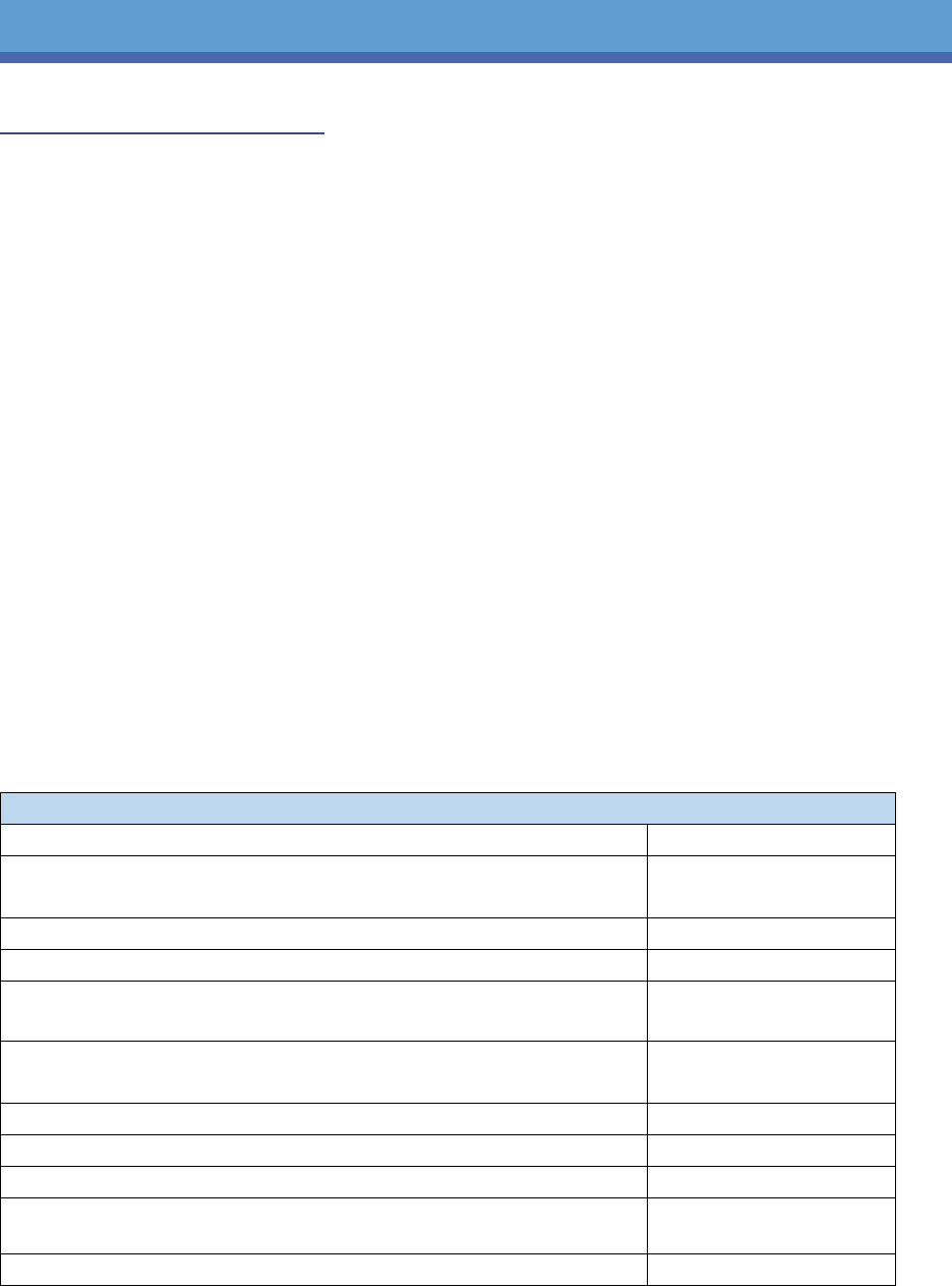
The tables below lists the building materials and specifications used in the design of the
Corporate Headquarters.
Structural Steel
Member
Grade
Wide Flange Shapes & WT Shapes
ASTM A992,UNO
Channels
ASTM A36, UNO
Angles
ASTM A36, UNO
Rectangular and Square Hollow Structural Sections
ASTM A500 GRADE B,
UNO
Round Hollow Structural Sections
ASTM A500 GRADE B,
UNO
Steel Pipe
ASTM A53 GRADE B
Steel Plates
ASTM A36, UNO
High Strength Bolts
ASTM A325 OR A490
Anchor Bolts
ASTM F1554, GRADE 36
AND GRADE 105
Standard Fasteners
ASTM A307
*UNO= unless nothed otherwise in drawings
TABLE X: STURCTURAL STEEL SPECIFICATIONS

CORPORATE HEADQUARTERS
M. JULIA HAVERTY | STRUCTURAL OPTION
TECHNICAL REPORT 1 6
Concrete
Application
Strength
(psi)
Weight
(pcf)
Spread Footings
3500
150
Walls, Piers, Grade Beams
4000
150
Slab on Grade
3500
150
Mud Mat
2000
150
TABLE X: CONCRETE SPECIFICATIONS
Reinforcement
Application
Grade
Deformed Bars
ASTM A615, Grade
60
Deformed Bars (Weldable)
ASTM A706
Welded Wire Fabric
ASTM A185
TABLE X: REINFORCING SPECIFICATIONS
Foundation System
A geotechnical report of the future site of the Corporate Headquarters was performed
by in February 2012 by Geo-Sci, Inc. Following the completion of the report, it was determined
that the soil bearing capacity would not be sufficient to support the weight of the building. In
order to increase the soil capacity, an aggregate pier soil reinforcement systems was utilized
below each free standing column footing. The size of the aggregate pier was determined by the
size of the column footing.
Due to the soil’s sensitivity to both weather and construction activity, it is required that
all footings, both column and wall, be excavated and poured on the same day so as not to
disturb the soil. If this cannot be achieved, a 3” concrete mud mat must be poured over top of
the excavated soil. For ease of constructability, the foundation is comprised of spread footings,
wall footings, column piers, grade beams, partial slab on grade.
This foundation of the Corporate Headquarters required the use of grade beams in order to
transmit the large dead load of the trees planted in the upper level courtyard. This is evident

CORPORATE HEADQUARTERS
M. JULIA HAVERTY | STRUCTURAL OPTION
TECHNICAL REPORT 1 7
due to the placement of the grade beams near the areas with courtyard access, namely, the
southwestern corner of the courtyard and the northwestern corner.
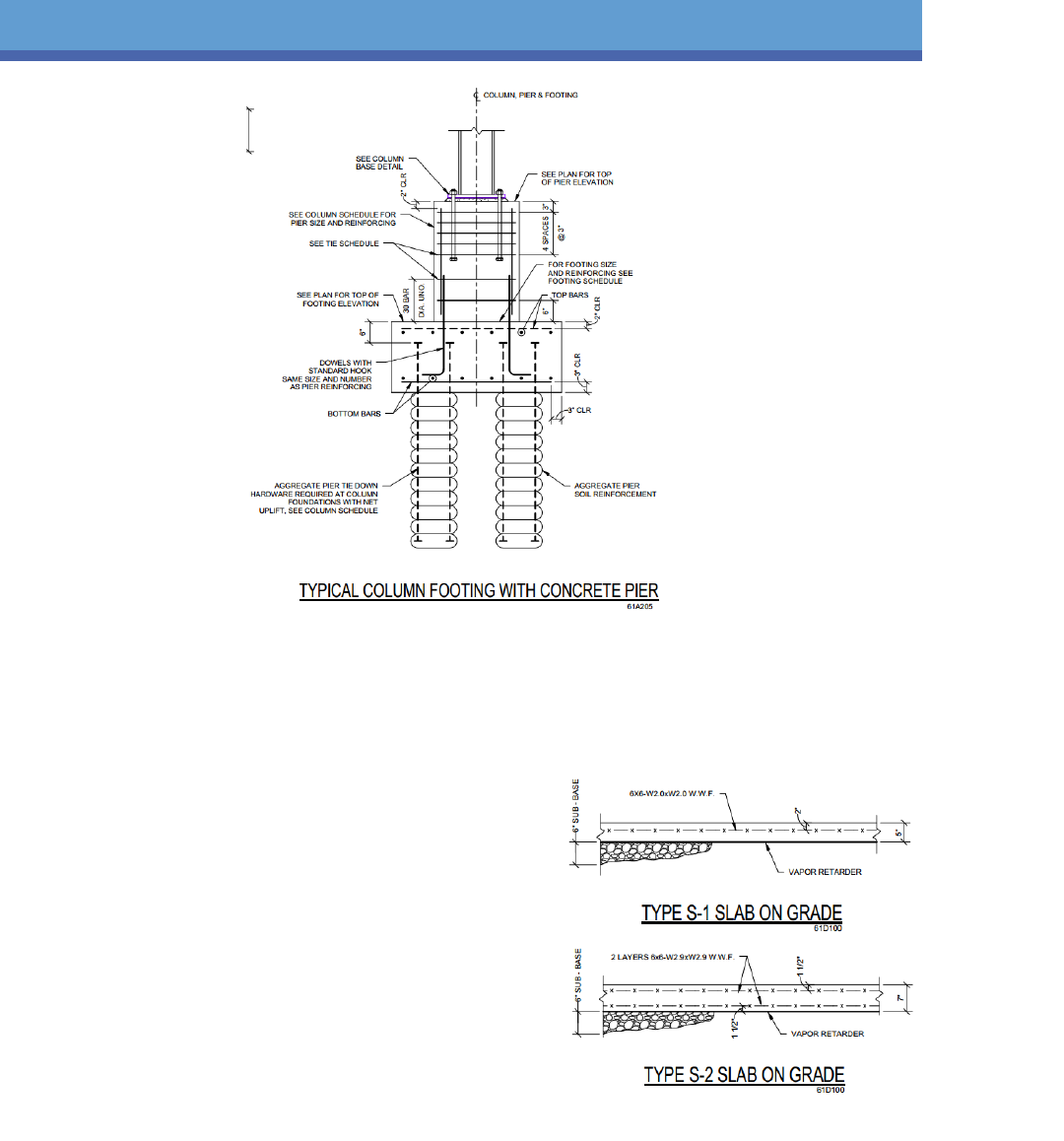
The typical spread footings (Figure 1) are centered under the base of the steel columns and are
placed directly above the aggregate piers used for soil reinforcement. Since there are no
moment frames within the structure of the building, it can be reasonably assumed that the
connections are pinned. For columns that sit on both a spread footing and concrete pier (Figure
2), the connection can also be assumed to be pinned. All spread footings in this building are
required to sit on aggregate piers due to the poor soil quality on the site.
FIGURE 1- TYPICAL STEEL COLUMN AND FOOTING
CORPORATE HEADQUARTERS
M. JULIA HAVERTY | STRUCTURAL OPTION
TECHNICAL REPORT 1 8
FIGURE 2- TYPICAL COLUMN FOOTING WITH CONCRETE PIER
Wall footings are used at all exterior wall locations
along the perimeter of the building, and most of the
building rests on a slab on grade foundation. The
larger slab depth (Type S-2 in) is used throughout
most of the northern half of the building since it is
slightly below grade. Slab Type S-1 is used primarily
near the center of the building, near the area of the
courtyard, and is typical slab on grade construction.
Both slab types can be seen in Figure 3.
FIGURE 3- SLAB ON GRADE DETAILS

CORPORATE HEADQUARTERS
M. JULIA HAVERTY | STRUCTURAL OPTION
TECHNICAL REPORT 1 9
Floor System
The Corporate Headquarter features two different construction assemblies for the floor
system. The first assembly (F-1) features 3 ¼” lightweight concrete with 6x6-W1.4xW1.4 welded
wire fabric reinforcement on top of a 2” 18 gage composite metal deck. Assembly F-2 has 4 ¼”
of lightweight concrete reinforced with 6x6-W2.0xW2.0 welded wire fabric on 3” 16 gage
composite metal deck. The decking runs perpendicular to the wide flange beams.
Typical Floor Bay
Many of the bays in the Corporate Headquarters are rectangular, and shapes only differ
near the edges of the building and the interior courtyard area. A typical beam span is
38’-0” to 40’-0” and a typical bay is between 33’-0” and 38’-0”. Two typical member
sizes used in all levels of floor framing are W21x44 W24x55, with slight variation when
spans are smaller. In the smaller span areas, such as around stair and elevator openings
and the courtyard, W18 shapes and W21 shapes are common. Typical interior girders
for a standard bay are W24x68, and in areas with smaller bays are typically W21 shapes
or lighter W24 shapes. Figure 4 below shows a typical 38’ bay and W24x55 beams.

CORPORATE HEADQUARTERS
M. JULIA HAVERTY | STRUCTURAL OPTION
TECHNICAL REPORT 1 10
FIGURE 4: LEVEL 4 FRAMING PLAN SHOWING TYPICAL BAY (S104.D)
CORPORATE HEADQUARTERS
M. JULIA HAVERTY | STRUCTURAL OPTION
TECHNICAL REPORT 1 11
Framing System
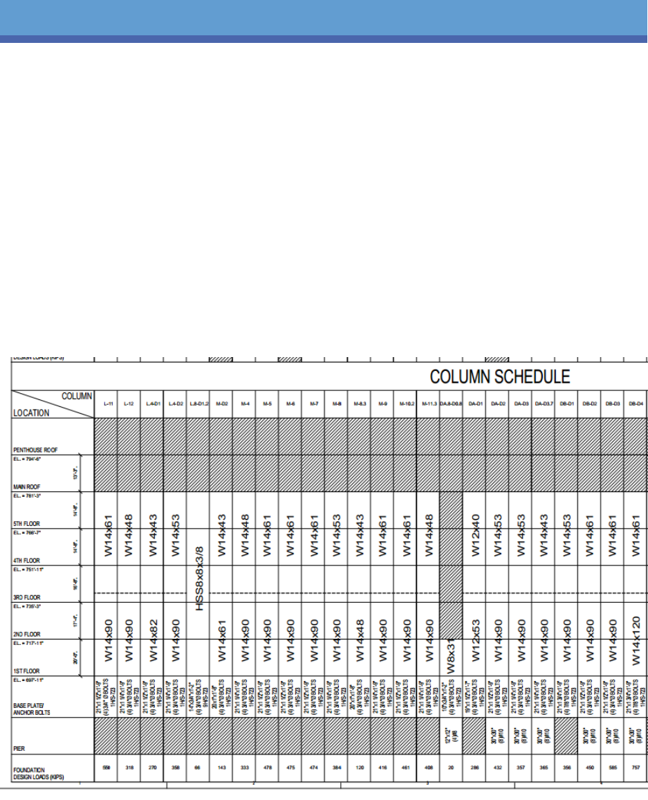
The primary structural framing of the building is composed of steel wide flange columns. All
columns are W14 or W12, with the majority of weights between 61 and 170. The one exception
to this is the lone HSS column that spans from the first floor to the roof. One feature that makes
the building unique is the number of column splices. Nearly every column in the building has a
column splice, and many of the spices are larger shapes on the bottom than the top. Every
combination of column splices varies slightly in size, with no predominant size majority. The
columns are typically spliced between level 2 and level 3, and several columns in the building
feature tension column splices.
FIGURE 5- COLUMN SCHEDULE

CORPORATE HEADQUARTERS
M. JULIA HAVERTY | STRUCTURAL OPTION
TECHNICAL REPORT 1 12
Lateral System
The lateral system of the Corporate Headquarters is made up of a series of braced frames near
the interior of the building. In six locations the braced frames rise from the first floor to the
roof, and in two locations the braced frames begin on the second floor level.
The brace legs are made of Hollow Structural Sections varying from HSS8x8x1/4 to HSS
16x16x5/8. In two locations, the bottom leg of the brace is made of a W14 shape. The braces
take the traditional diagonal shape in five locations, a chevron shape in one location, and an
inverted chevron shape in two locations.
The brace frames were used as the primary lateral force resistance method in their respective
areas due to their lightweight in comparison to shear walls and their ease of constructability.
The majority of the braced frames transfer their loads down to grade beams at the building’s
foundation level.
FIGURE 6- SAMPLE BRACED FRAME ELEVATIONS

CORPORATE HEADQUARTERS
M. JULIA HAVERTY | STRUCTURAL OPTION
TECHNICAL REPORT 1 13
Joint Details
The typical connections found in the Corporate Headquarters are column splices, floor
to curtain wall, and moment connections to columns. In the following section, each connection
type will be briefly described and accompanied by an image from the structural drawings.
Column Splices
Column splices typically occur between floor 2 and floor 3 within the corporate
headquarters. The columns are attached using welding or bolted splice plates and must
be developed to have a minimum of 10% of the tensile capacity of the column flanges.
FIGURE 7- TYPICAL COLUMN SPLICE

CORPORATE HEADQUARTERS
M. JULIA HAVERTY | STRUCTURAL OPTION
TECHNICAL REPORT 1 14
Floor to Curtain Wall Connection
The floor system is connection to the curtain wall via a gravity and lateral connection
piece that sits in the middle of the curtain wall channel. The connection utilizes a bent
plate with long headed studs for extra support.
FIGURE 8-TYPICAL FLOOR TO CURTAIN WALL CONNECTION

CORPORATE HEADQUARTERS
M. JULIA HAVERTY | STRUCTURAL OPTION
TECHNICAL REPORT 1 15
Moment Connection to Columns
To achieve the moment connection to the column web, the members are welded in
place using a weld plate. The stiffener plates used in the connection process are
required to have the same yield strength and thickness as the flange of the beam, which
is typically ¼”. Additionally, each bolted connection used will be slip critical due to the
possibility of oversized holes within the members.
FIGURE 9- TYPICAL MOMENT CONNECTION TO COLUMN

CORPORATE HEADQUARTERS
M. JULIA HAVERTY | STRUCTURAL OPTION
TECHNICAL REPORT 1 16
Design Codes and Standards
The following design codes and standards used during the structural design of the
Corporate Headquarters.
International Code Council
International Building Code 2009
o Incorporated by 2011 Ohio Building Code
American Society of Civil Engineers
ASCE 7-05: Minimum Design Loads for Buildings and Other Structures
o Referenced by IBC 2009
American Concrete Institute
ACI 530: Building Code Requirements for Masonry Structures
o ACI 530.1: Specifications for Masonry Structures
American Institute of Steel Construction
AISC 360-05: Specifications for Structural Steel Buildings
o Supersedes the Load Resistance Factor Design Specification for
Structural Steel Buildings, as given on drawings
American Welding Society
AWS D1.1: Structural Welding Code- Steel

CORPORATE HEADQUARTERS
M. JULIA HAVERTY | STRUCTURAL OPTION
TECHNICAL REPORT 1 17
Design Loads
The focus of this section are the load values used during the structural design of the
Corporate Headquarters. Dead, live, snow, wind, and seismic loads were calculated using the
2011 Ohio Building Code, which adopts IBC 2009, which references ASCE 7-05.
National Code for Live Loads and Lateral Loadings
Live and Lateral loads for the Corporate Headquarters were calculated using 2011 Ohio Building
Code, which adopts IBC 2009 and references ASCE 7-05.
Gravity Loads
Live Loads:
The live loading schedule for this project is listed on sheet S-001. Nearly every
value listed in the drawings can be found in ASCE 7-05, Table 4-1, except for Kitchen
Refrigerator and Freezer Area, and Typical and RTU Roof Areas. The loads not able to be
determined by ASCE 7-05 are explained in greater detail in the table below.

CORPORATE HEADQUARTERS
M. JULIA HAVERTY | STRUCTURAL OPTION
TECHNICAL REPORT 1 18
Load
Determination of Load
Kitchen Refrigerator and Freezer Area
Due to heavy traffic during the lunch hour as
well as the weight of the equipment and its
ability to move, the space was designed for
a heavier load than a typical “light storage
warehouse.”
Typical Roof
A typical flat roof requires only 20 psf LL, but
this was upsized by 5 psf since no live load
reduction was utilized.
RTU Roof Areas
No live load reduction utilized, therefore
higher initial live load.
Dead Loads:
The dead load values for this project can be found on sheet S-001 and are based
on industry standards as well as the engineering judgment of the structural design
engineer. Certain dead load values, such as ceiling weight, MEP, and insulation are
based off assumptions.
Snow Loads
The design snow loads are based on the snow load maps found in IBC 2009, which reference
ASCE 7-05. The design loads and factors are listed on sheet S-001 and include the provisions for
drifting snow.
Lateral Loads
Wind Loads:
The design wind loads for this building were split up into two different sets of
criteria: wind loading for the main wind-force resisting system and wind loading for
components and cladding. The overall design criteria for the building’s structural design

CORPORATE HEADQUARTERS
M. JULIA HAVERTY | STRUCTURAL OPTION
TECHNICAL REPORT 1 19
are in accordance with the 2011 Ohio Building Code, which incorporates the 2009 IBC,
which adopted ASCE 7-05. Section 6 of ASCE 7-05 describes the procedure for
determining wind loads with given factors. Those factors, as well as the basic wind
speed, can be found in the design criteria on sheet S-001.
Seismic Loads:
Seismic design loads were determined based on ASCE 7-05, Section 12: Seismic
Design Requirements for Building Structures. The factors needed to determine exact
seismic loading can be found in the design criteria on sheet S-001.
Soil Loads
Soil loads for the building were calculated using the geotechnical report provided by Geo-Sci,
Inc. as well as the 2011 Ohio Building Code, Section 1806.

CORPORATE HEADQUARTERS
M. JULIA HAVERTY | STRUCTURAL OPTION
TECHNICAL REPORT 1 20
Load Paths
Gravity Load Path
As loads are applied to a floor, the composite floor decking will carry the load and transfer it
onto the beams and girders in the floor framing. Once the load is taken by the framing, it is
shifted down the columns and is transferred onto the column footings, grade beams, and piers.
At that point, the foundation dissipates the load into the soil below.
The roof and courtyard green space follow a similar load path, taking loads and carrying them
through the deck onto the framing until they hit columns, the foundation, and eventually, the
soil.
Lateral Load Path
The building’s façade takes the distributed wind load and transfers it through the floor system.
The floor carries the load to the brace frames throughout the building and send the force down
to the foundation, where the load is dissipated into the soil.

CORPORATE HEADQUARTERS
M. JULIA HAVERTY | STRUCTURAL OPTION
TECHNICAL REPORT 1 21
Conclusion
Technical Report 1 described the existing structural conditions of the Corporate
Headquarters. The report included detailed descriptions of the foundations, floor systems,
framing systems, lateral systems, typical joint conditions, design codes and standards, and
loading.
The architectural design of the Corporate Headquarters was inspired by the surrounding
existing buildings in the retail park just to the north of the site. Since the new building will serve
as a south entrance to the park, it was determined that the architecture should blend and have
a fluid feel as a guest walked from one end of the park to the other. The architectural design
and precedent buildings will have an impact on future assignments since changes made to the
building façade will have to keep the same basic architectural style of face brick and glass.
A major challenge in the building design was the poor soil quality and the request for
the interior courtyard. The poor soil quality required that aggregate piers be placed down in the
soil for column spread footings and piers to brace on. The interior courtyard also provided a
challenge since gravity loads from the upper floors had to take a different load path. The poor
soil quality could be a challenge and must be considered in future assignments.
The braced frame system will be challenging in future assignments due to its placement.
The braced frames lie near the core of the building, rather than on the perimeter, so designing
around them will be challenging. Additionally, the brace frames must be more fully considered
in future load paths. Since the interior composition of the space is so important to the
company, the braced frame must be completely hidden from view in future design and analysis.

CORPORATE HEADQUARTERS
M. JULIA HAVERTY | STRUCTURAL OPTION
TECHNICAL REPORT 1 22
Appendices
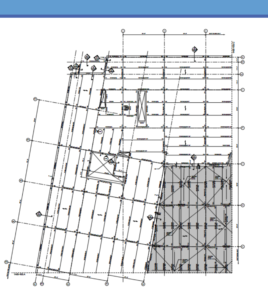
Appendix A: Typical Building Floor Plans
Building Key Plan
FIGURE 10- TYPICAL SEGMENT A FLOOR FRAMING PLAN
CORPORATE HEADQUARTERS
M. JULIA HAVERTY | STRUCTURAL OPTION
TECHNICAL REPORT 1 23
FIGURE 11- TYPICAL SEGMENT B FLOOR FRAMING PLAN

CORPORATE HEADQUARTERS
M. JULIA HAVERTY | STRUCTURAL OPTION
TECHNICAL REPORT 1 24
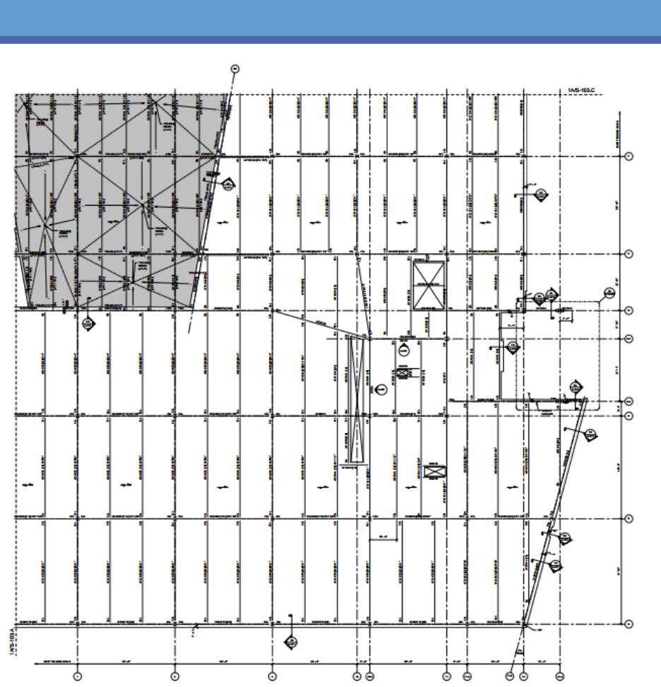
FIGURE 12-TYPICAL SEGMENT C FLOOR FRAMING PLAN
CORPORATE HEADQUARTERS
M. JULIA HAVERTY | STRUCTURAL OPTION
TECHNICAL REPORT 1 25
FIGURE 13-TYPICAL SEGMENT D FLOOR FRAMING PLAN

CORPORATE HEADQUARTERS
M. JULIA HAVERTY | STRUCTURAL OPTION
TECHNICAL REPORT 1 26
Appendix B: Building Elevations
FIGURE 14- BUILDING ELEVATIONS, FROM TOP DOWN: SOUTH, WEST, NORTH, EAST
