
Quick Start Guide – Revision 1B
This document is copyright © VGP Media Ltd 2019
All rights reserved worldwide
VideoGameperfection.com is a trading name of VGP Media Ltd
Registered in Republic of Ireland number 637539
OSSC Quick Start Guide VideoGamePerfection.com
Open Source Scan Converter – Quick Start Guide (Rev 1B)
Contents
Important safety information......................................................................................................3
Overview (v1.5 and earlier revision units)..................................................................................4
Overview (v1.6 and later revision units).....................................................................................4
Buttons, connectors and external controls..................................................................................5
Connecting your OSSC...............................................................................................................6
Connecting a console, PCB or other hardware...........................................................................6
Options........................................................................................................................................6
Scanlines.....................................................................................................................................7
Line triple, quadruple and quintuple...........................................................................................7
Interlace video and the OSSC.....................................................................................................8
Fine tuning the image..................................................................................................................8
Audio input and output...............................................................................................................8
Firmware updates........................................................................................................................9
Troubleshooting........................................................................................................................10
More information......................................................................................................................11
Disposing of your OSSC...........................................................................................................11
Thank you for purchasing the Open Source Scan Converter (OSSC). Please take time to read
through this short document before you start using the unit.
Page 2
Important safety information
Please observe the following safety precautions when using your OSSC.
Use the correct power supply – OSSC is designed to run with a 5 volt, 2.1 x 5.5mm positive tip
power supply unit (PSU) supplying at least 1 amp of current. Please ensure your power supply
meets these requirements. Never connect a power supply that supplies more than 5 volts. Doing so
can damage the OSSC.
Turn off the power before connecting/disconnecting equipment – To prevent damage of the
OSSCs integrated circuits, always turn off the power before connecting to a display or a device.
Do not expose to moisture – Droplets of moisture may contact the PCB and cause a short circuit.
Never submerge the unit in water.
Keep away from fire or high heat sources – OSSC is not flammable but high temperatures, such
as those from a fire or electric heater may melt the plastic casing.
Please supervise children – OSSC is not a toy and is not designed for use by children. Please
supervise children if they use the OSSC.
Beware of using the OSSCs deinterlacer on sources that display static graphics or text for a
long period of time – OSSCs deinterlacer produces a constant flickering effect. This can cause
image retention/burn in to occur faster than normal. See page 8 for more information.

OSSC Quick Start Guide VideoGamePerfection.com
Overview (v1.5 and earlier revision units)
Remote Control (optional)
Overview (v1.6 and later revision units)
The pictures above show a 1.5 revision OSSC, if you purchased a 1.6 revision, the unit will look the
same apart from the side with the video output connector.
OSSC revision 1.6 has an additional
3.5mm audio connector and comes
with a HDMI compatible video
connector. There is also an additional
audio toggle switch. Otherwise, all
connections and controls are the same
as previously.
Page 4
Buttons, connectors and external controls
In the overview pictures you can see the following features on your OSSC.
Status LEDs – Green LED indicates that power is on. This green LED will go out briefly when an
IR remote code is detected. The red LED indicates unstable sync when lit.
LCD – Displays the OSSCs menus and information about the current source.
MicroSD Card Slot – For updating the devices firmware, see “Firmware Updates”.
IR Sensor – Receives commands from the remote control unit. Line of sight is required.
JTAG Connector – For software development purposes and firmware updates.
BTN0 and BTN1 – Perform various functions without the need of a remote.
Video out – On 1.5 and earlier models, an industry standard DVI-D connector outputs digital video
at chosen resolution to your display. Does not support/output analogue DVI. On 1.6 models this is
replaced by a HDMI connector.
Audio out (V1.5 and earlier revisions only) – Standard 3.5mm stereo headphone plug type
connector. Audio fed in through AV1 (RGB SCART) will be output here. If an audio upgrade board
is installed, you can also feed in analogue audio through this connection, but please note if you do
you should disconnect the SCART cable from AV1.
AV2 audio in/AV1 audio out (V1.6 and later revision units only) - Standard 3.5mm stereo
headphone plug type connector. Use this connector to output audio from AV1/SCART or to input
audio for AV2/Component video sources.
Audio toggle (V1.6 and later revision units only) – Toggle between outputting audio from AV1 or
inputting and digitising audio on AV2.
AV3 audio in (V1.6 and later revision units only) - Standard 3.5mm stereo headphone plug type
connector. Use this connector to input and digitise audio for AV3/D-Sub15 (VGA) sources.
AV1 In – Connect an RGB SCART source to this input. Note the input must be RGB or Ypbpr, S-
video and composite SCART sources are not supported and require transcoding into RGB first.
Only European spec RGB SCART cables are supported, the less common Japanese JP21 cables
must be used with a converter, a suitable one can be purchased here -
https://www.retrogamingcables.co.uk/micomsoft-xrgb/european-scart-to-japanese-scart-converter
AV2 In – Connect component video or RGB with sync on green sources to this input.
AV3 In – Standard D-Sub15 (VGA) connector. You can connect sources such as the Sega
Dreamcast or a retro gaming PC. This input does NOT have a sync low pass filter as this is
normally not required for VGA connections.
Signals up to a maximum resolution of 720p are supported on all inputs.
Power Switch – Toggles power off and on.
OSSC Quick Start Guide VideoGamePerfection.com
Power input – Connect a suitable 5 volt, 2.1 x 5.5mm positive tip PSU supplying at least 1 amp of
current.
The OSSC has been designed as a next-generation line-doubler. Rather than a fully blown video
processor, the OSSC is designed to process individual scanlines in real time. Because of this, the
unit can convert between the 15khz video that your retro consoles output and the 31khz video that
modern displays work best with, with only a few microseconds of input lag.
Connecting your OSSC
Connect a suitable power supply (5 volts, 1 amp postive tip) to the
OSSCs power connector. Connect a DVI or HDMI cable between the
video out on the OSSC and your display. Almost any display that
supports HDMI or DVI-D can be used, but please remember OSSC does
not adhere fully to DVI/HDMI specifications so compatibility cannot be
guaranteed. For displays that only have analogue inputs, a converter is
required. OSSC does not use HDCP, so any basic converter should work.
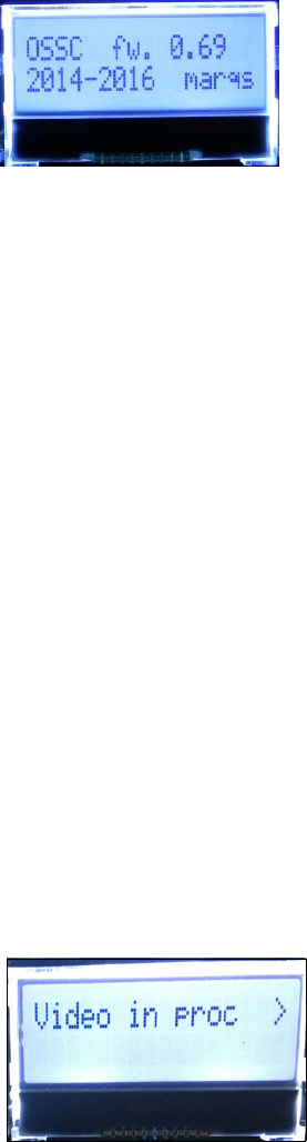
Ensure the PSU is turned on at the wall, then power on your OSSC using the power switch, the
LCD on the front of the unit should light up and display the current firmware version, as shown in
the picture. A letter ‘a’ after the firmware version number indicates audio capable firmware. Switch
your display to the correct input. If everything is working correctly, a grey test card pattern should
appear.
Connecting a console, PCB or other hardware
Power your OSSC off and connect a suitable source to the AV1, AV2 or AV3 connectors. For most
systems, using a properly wired RGB SCART cable connected to the AV1 input is the best option.
You can connect either 15khz or 31khz sources to any input on the OSSC, but remember that the
AV3 (VGA or D-Sub15) connector does not have the additional filtering that RGB SCART sources
often require.
Once you have connected your hardware, power on the OSSC. Select the appropriate input using
the remote or by pressing BTN0 until the LCD displays the correct input. Now, power on your
console, PCB or vintage computer hardware. You should now see it displayed on your TV or
monitor.
Options
To access the OSSCs options menu, press the Menu on/off button on
the remote. The LCD on the front of the unit will then change to menu
mode, as shown in the picture on the left.
In the newer firmwares, options are now organised into sub-
categories. You can navigate between categories using the Prev/next
option buttons on the remote and select an option using OK button.
Page 6
You can then change the values of various options using the Value -/+ buttons. For details of all the
options, see the wiki page here:- http://junkerhq.net/xrgb/index.php/OSSC
Scanlines
Vintage games consoles such as the Sega Megadrive and Nintendo NES used a special screen mode
which resulted in alternating lines on a CRT display being left blank. Typically when people in the
retro-gaming communities refer to scanlines, they mean the blank lines between parts of an image
on a CRT that were a result of this screen mode. OSSC allows you to simulate these scanlines,
making the image look more authentic. You can enable or disable scanlines on the OSSC by using
the menu and navigating to “Post-Proc” and then “Scanlines”. Setting scanlines to “Auto” means
that scanlines appear only on 240p/288p sources, while “Manual” scanlines will appear over all
sources regardless of original resolution. Alternatively you can toggle scanlines by pressing BTN1
on the device, or by pressing the Scanline Mode button on the remote control.
You can also configure scanline strength from the OSSC menu, or by using the Scanline Int button
on the remote. How pronounced the scanlines would look on a real CRT varies greatly between
displays, so set the scanline strength to your taste.
Line triple, quadruple and quintuple
By default the OSSC takes in one scanline and outputs two, resulting in a lag free conversion of
240p to 480p. Line triple mode (Line3x) attempts to triple each scanline instead. OSSC now offers a
line quadruple and quintuple mode too (hereafter referred to as Line4x and Line5x respectively).
These modes can result in a very sharp image on compatible displays. Unfortunately, not every
display is compatible.
To change the line multiplication mode, press the Menu on/off button so that the OSSC menu is
displayed on the LCD and then navigate to “Output opt”, select this and then navigate to
“240p/288p Proc”. Use the prev/next buttons on the remote to choose the desired multiplication
mode. For most sources you should also check that your chosen line multiplication mode is set to
“Generic 4:3”. While still on the Output opt menu, use the remote to select “Line3x mode” (or the
appropriate setting for your chosen line multiplication setting) and ensure that it is set to “Generic
4:3”.
For Line5x mode, you can also choose the picture format under “Line5x format”. The available
options are 1920x1080, 1600x1200 or 1920x1200. If your display supports 1600x1200 or
1920x1200 then using these modes will display the full image on your display. In 1920x1080 mode,
parts of the image will be cropped.
You cannot damage your display by trying the line multiplication modes. If your display refuses to
show a picture, simply use the LCD to turn line triple mode off again. There are a small number of
displays that are more compatible in line triple mode.
OSSC Quick Start Guide VideoGamePerfection.com
Interlace video and the OSSC
Certain retro consoles and computers (e.g Sony PS2, Nintendo Gamecube) output in interlace
modes. These modes send alternating scanlines to the display in each frame and were how standard
definition analogue television was broadcast. To display interlace video on modern displays, it must
be deinterlaced first. As with progressive sources, the OSSC can deinterlace content like this with
no input lag. However, the image that is produced tends to exhibit some flickering and combing
artefacts.
OSSC is a line doubler and therefore cannot perform sophisticated deinterlacing because it does not
have a frame buffer. Because of this, you can choose to use the OSSCs deinterlacing or your
displays built in deinterlacer (if available).
The rule of thumb is, if your priority is a good picture, use your displays deinterlacer. If your
priority is reducing input lag, let the OSSC handle deinterlacing.
To toggle between the two deinterlacing options, press the menu button on the remote and navigate
to “Output opt”. Press the OK button, then navigate to “480i/576i Proc”. Now, choose “Passthru” to
use your displays deinterlacer, or any other option to use the OSSCs deinterlacing. “Line 2x (Bob)”
is the most common and most compatible option.
Try to avoid interlace software and modes where possible. It is not possible to have both low input
lag and excellent picture quality with interlace sources. If your software title supports progressive or
480p mode then be sure to enable this. Beware of using the OSSCs deinterlacer on sources that
display static graphics or text for a long period of time. The constant flickering can cause image
retention/burn in to occur faster than normal.
Fine tuning the image
By exploring the OSSCs menus you will notice options such as “Video LPF”, “Analog Sync LPF”
and “H-PLL Post-Coast” and various others. These options can be used to fine tune the image or to
fix compatibility problems. The OSSCs default settings are fine for most sources. For specific
recommendations, see the wiki page here http://junkerhq.net/xrgb/index.php/OSSC
Audio input and output
Digital audio output is standard on OSSC 1.6 and can be added to earlier model OSSCs by
installing an audio expansion board. You can also connect your OSSC's audio to an external hi-fi or
home theatre system via the 3.5mm audio connector.
Remember, routing your OSSCs video output through equipment such as home theatre receivers or
video processors can in many instances add input lag. Routing the signal through home theatre
receivers, switches, splitters, audio integrators or other video processors can also increase the time it
takes to re-sync the signal on game titles which switch between 480i and 240p screen modes.
When using OSSC 1.5 or earlier with an audio expansion board, any audio fed in via AV1 or the
3.5mm audio connector will be digitised no matter which video input is selected. For OSSC 1.6, the
appropriate audio input will be used depending on the active video input.
Page 8
Firmware updates
New features are periodically added to the OSSC in the form of firmware updates. The devices
firmware can be updated using an SD card. The SD card should first be formatted with the new
firmware. Once this is done, insert the card into the OSSC, enter the menu and choose “FW.
update”.
To check for the latest firmware and to see a tutorial on how to correctly update the firmware on
your device, visit this page:- videogameperfection.com/ossc-fw
The firmware files are named using the following conventions:-
-jp – Japanese language version
-aud – Digital audio enabled version suitable for OSSCs with audio expansion board or OSSC 1.6.

OSSC Quick Start Guide VideoGamePerfection.com
Troubleshooting
Symptom Possible Cause Solution
Certain Genesis/Megadrive games
(Sonic 2, Fix it Felix) do not work
Coast values need changing Set H-PLL coast pre 3 and post 3
Image has a vertical flicker/shimmer
effect
Interlace source connected This is a normal side effect of lag-free
deinterlacing, no action is required
Image unstable and/or flickers on and
off
Nintendo SNES/Super Famicom
console connected
Try a different display or install a de-
jitter board to your console.
Horizontal jitter/wobble on image Fine tuning required Try adjusting low pass filter settings.
See the wiki for recommendations
Missing pixels in the image Wrong line triple mode selected Use generic 4:3 or Generic 16:9 line
triple mode instead
No audio Display incompatibility Use a different display or choose a
different line multiplication mode
No audio Sample mode incompatible Change the Down-sampling option
under “Audio options” to 2x
No audio on AV2 Audio toggle switch set to input mode Change audio toggle switch (next to
HDMI connector)
No image Sync mode set wrong Press the source button again to
change sync mode. Most common
sync type is RGBs for SCART, YPbPr
for component and RGBHV for
DSub15/VGA
No image Line triple/quadruple/quintuple
enabled
Switch to line double mode. Other
modes are not compatible with all
displays
No image HDMI/DVI handshake failed Power cycle the OSSC
No image Unusual sync signal Power off OSSC and your source.
Power on the OSSC and select the
correct input, then power on your
source
No image and LCD says NO SYNC Source not powered on Check power to source device
No image and LCD says NO SYNC Source not outputting RGB or YPbPr Make sure your source device outputs
RGB and your SCART cable is wired
for RGB
OSSC Resets/reboots Power supply not suitable Use a different PSU with at least 1
amp of current. You can purchase a
suitable PSU at
Videogameperfection.com
Page 10

More information
For more information on using your OSSC, see the OSSC Wiki page here –
junkerhq.net/xrgb/index.php/OSSC
For technical support, visit the support forums here -
https://www.videogameperfection.com/forums/forum/ossc/
Disposing of your OSSC
If your OSSC malfunctions, please contact us via e-mail or through our website to
arrange repair or replacement. All OSSC units sold by VideogamePerfection.com/
VGP Media come with one years warranty. Outside of warranty, we can service
and repair most faulty units.
Please consider contacting us before disposing of your OSSC, even if you no
longer want it. If you do need to dispose of the unit, in most countries you can
recycle the unit for free at your local recycling centre. To find your nearest centre in the UK, visit
the Recycle More website at http://www.recycle-more.co.uk and type in your postcode. In the
Republic of Ireland, visit https://www.weeeireland.ie/household-recycling/where-can-i-recycle/
If you live outside of the UK or ROI, please check with local authorities or contact us to arrange for
a return of your unit.
