
1
[Date]
A Project Report on
AUTOMATIC BIKE LOCKING SYSTEM
THROUGH FINGERPRIENT SENSOR
Submitted in partial fulfillment of the requirements for the award of Bachelor of
Engineering / Technologydegree in Electronics and Communication
Engineering.
UNDER THE GUIDANCE :
Mrs.Dr.Rekha Chakravarthi, Assistant Professor in Dept of Electroics and
Communication Engineering.
SUBMITTED BY :
Pathakunta Muralidhar Reddy - 38130156
Mettu Raghunath Reddy - 38130134
DEPARTMENT OF ELECTRONICS AND
COMMUNICATION ENGINEERING
SCHOOL OF ELECTRONICS AND
COMMUNICATION ENGINEERING
SATHYABAMA INSTITUTE OF SCIENCE AND
TECHNOLOGY
(DEEMED TO BE UNIVERSITY)
Accredited with Grade “A” by NAAc I 12B Status by UGC I
Approved by
AICTE JEPPIAR NAGAR,RAJIV GANDHI
SALAI,CHENNAI – 600119

2
[Date]
ABSTARCT:
This fingerprint system is a project to prevent motorcycle thefts these days. So with our
project or initiative, this will reduce the risk of thefts that happen in india. We got this idea
based on the collected problem statement which is nowadays motorcycle are easily being stolen
by the thieves. The objective of this project is to upgrade the safety system, to ease the ignition
of the bike and reduce the loss of motorcycles in the present time. Basically, we are making a
new way to start a bike that is originally used starter. By using our project, they can ignite their
motorcycle just by using their fingerprint. In our preliminary study, this project requires us to
study about electronic devices and circuits. Thus, we have to make research to make a circuit
so the fingerprint sensor will work well. In conclusion, we hope our project could decrease the
rate of stolen motorcycle and give a new interesting way of starting your motorcycle.

3
[Date]
TABLE OF CONTENTS:-
INTRODUCTION…………………………………………………………………………………….4
CHAPTER 2 LITERATURE SURVEY………………………………………………………….....5
CHAPTER 3………………………………………………………………………………………..17
3.1 EXISTING SYSTEM………………………………………………………………………...17
3.2 PROPOSED SYSTEM………………………………………………………………………17
BLOCK DIAGRAM……………………………………………………………………..19
HARDWARE AND SOFTWARE REQUIRED………………………………………19
CHAPTER 4…………………………………………………………………………………….. 20
4.1 OVERVIEW………………………………………………………………………………….21
4.2 SUMMERY…………………………………………………………………………………..22
4.3 PIN CONFIGUARATION…………………………………………………………………23
4.4 COMMUNICATION……………………………………………………………………….26
4.5 ARUDINO SOFTWARE…………………………………………………………………...29
CHAPTER 5
RESULT AND DISCUSSIONS……………………………………………………………….37
CONCLUSION AND FUTURE SCOPE……………………………………………………39
REFERENCES…………………………………………………………………………………40

4
[Date]
CHAPTER 1
INTRODUCTION
Motorcycle fingerprint sensor is our project for final year project. This project is inspired from
the smartphone fingerprint sensor that is widely used in any smartphones in this world. We
cannot unlock our phone if the sensor cannot recognize the fingerprint and this way is safer
than using the old way which is pin lock or pattern lock. Nobody can use your phone unless
you open it with your own fingerprint. Because of this, we would like to apply this application
for motorcycle due to the increased number of stolen motorcycle cases lately. This case is
getting worst and it does not only happen to the moped bike, this case only happens at the
superbike. But for the superbike, it is not so famous because stealing a superbike is not that
easy like stealing a moped bike.

5
[Date]
CHAPTER 2
LITERATURE SURVEY
2.1 Anti-Theft Protection of Vehicles by using Fingerprint
The use of vehicle is a must for everyone. In the same way, safeguarding the vehicle against
theft is also very essential and it is done by vehicle tracking system. The roots of Vehicle
Tracking Systems lie in shipping industry. They required some sort of system to determine
where each vehicle was at any given time and for how long it travelled. Modern vehicle tracking
uses the active vehicle tracking and GPS technology. This technology provides with a split
screen view when reviewing your driver's route. Stop and transit times, as well as speed
information, are displayed in the bottom pane. It can easily toggle between stops by clicking
the stop number on the track detail pane and the system can save the information about the
engine that it is in working condition or stop by ignition ON/OFF detection. Fingerprint sensor
captures the fingerprint images, matches the uniqueness of each print read by the sensor and
compares it to the one stored in its module or local system database. A vehicle tracking system
that works using GPS and GSM technology, which would be the cheapest source of vehicle
tracking and it would work as anti-theft system. It is an embedded system which is used for
tracking and positioning of any vehicle by using Global Positioning System (GPS) and Global
system for mobile communication (GSM).
The vehicle tracking system is designed and Implemented for tracking the movement of any
equipped vehicle from any location at any time. The designed in-vehicle device works using
global positioning system and global system for mobile (GSM) communication/general packet
radio service (GSM/GPRS) technology .the device is embedded inside a vehicle whose position
is to be determined and tracked in real time. A microcontroller is used to control the GSM and
GSM/GPRS modules.GPS modules get geographic coordinates at regular interval of time and
GSM/GPRSmodule is used to transmit and update the vehicle location to the database. A GPS
tracking unit is a device that uses the Global Positioning System to determine the precise

6
[Date]
location of a vehicle, person, or other asset to which it is attached and to record the position of
the asset at regular intervals. The recorded location data can be stored within the tracking unit,
or it may be transmitted to a central location data base, or internet-connected computer, using
a cellular (GPRS).This allows the asset's location to be displayed against a map backdrop either
in real-time or when analyzing the track later, using customized software.The prevention of the
vehicle from probable theft is the main aim of the project. To achieve this we are incorporating
security by including biometrics, i.e a fingerprint. In the beginning the owner of the vehicle
must store his/her own fingerprint in the finger print module. The GSM modem is used to send
and receive messages to and from the owner. The owner’s mobile number has to be set fixed
during the coding. To start the ignition of the four-wheeler one should enter the authorized
fingerprint. If anyone enters an unregistered fingerprint, the owner will immediately receive a
message and the local alarm system will be turned on. For theft prevention, we can also trace
the four-wheeler by giving a call to the GSM modemwhich is embedded on the system. Then
real time tracking begins and the GPS location of the vehicle is sent to the owner by SMS. The
ignition of the vehicle can also be controller through notifications to the system. The vehicle
tracking system consists of a GPS receiver which provides real time position of the automobile.
This real time data is deposited in MMC(Main Memory Module) after a set time of intermission
by the MCU(Main Control Unit). GSM module is undoubtedly associated with the MCU which
is then used to propel and receive the SMS. GSM module takes the information from the MMC
and sends this information to the registered user’s mobile cell phone. This data consists of
longitude, latitude, altitude, the speed over ground, and the course over ground, the real time
and date. By using Google maps we can then locate the exact location of vehicle. The vehicle
tracking system also has another singular feature which tells not only the whereabouts of
vehicle but also securing the automobile. To know the location of the automobile, it is necessary
to stop the automobile as soon as possible. For repossessing the automobile, we are using to
convey the message in such a way they are allied to the buzzer and other is associated to the
power supply of the engine of automobile. User can simply deactivate the engine of automobile
by sending a message from his cell phone and we can get the automobile back very
soon.Passwords are the weakest component of many important security systems, so there is an
interrelated push from various directions towards passwords with less friable security
measures. The main emphasis while developing this vehicles anti-theft system was to assimilate
the above features equally. The most significant feature is the vehicle security from theft and it
has been guaranteed by providing certain layers of anti-theft protection.

7
[Date]
The process of implementation starts with the initialization of LCD and GSM modem. After
all the components are initialized, the user can directly control the device by sending a text
message. This design also allows a person near the device to access it, if that person is given
permission by the authenticated user. The person near the device terminal, inputs his fingerprint
in the fingerprint sensor. If the fingerprint is a valid image, then a message will be sent to the
device owner for access permission. If the owner of the device sends an access granting
message, then the person near the device can control it manually. But if the fingerprint image
is found invalid, the LCD will show “invalid user” message and access will not be given to that
person.The testing conditions for this project include several authorized and unauthorized
attempts to access the system. In this paper an alternative approach for device switching which
combines fingerprint identification technique with GSM and GPS functionalities has been
proposed.This approach allows more than one person to control the device functionality and
the authentication facility provided by the fingerprint sensor helps to reduce the fault correction
time. The Arduino board used in this model is least expensive and can be implemented in
various applications. The application of device switching is not limited to control device from
a long distance, but it can also be used in automobile applications. The proposed design not
only provides switching functionality, but also provides the exact location of the device. Hence
theft of the device can easily be detected. It gives complete knowledge of designing
microcontroller based system and developing embedded software. In the future work cloud
computing can be included to this project so that every activity performed on the device can be
closely monitored. This reduces the need for storing all the log-in information in the computer
storage.
2.2 Finger Print Based Bank Locker Security System
The main goal of this project is to design and implement a bank locker security system based
on Finger print and OTP technology. This can be organized in bank, offices and homes. In this
system only the authenticate person recover the documents or money from the lockers. In this
security system fingerprint and OTP is used. In this system first person enroll user name and
password and mobile number. If user name and password matches then Finger of person will
detect and store with ID. If the ID gets matches. Then four digit code will be sent on authorized
person mobile to unlock. So biometric and Bluetooth security is more advantages than other
system. This system can also create a log containing check in and checkout of each user along
with basic information.

8
[Date]
In the real world, peoples are more concerned about their safety for their valuable things like
jewellery, money, important documents etc. So the bank lockers are the safest place to store
them. The arrival of fast growing technologies makes users to have high security systems with
electronic identification options. These identification technologies include Bank Lockers and
ATM as well as other intelligent cards, user IDs and password based systems, and so on. But,
unfortunately these are not protected due to hacker attacks, thefts, and forgotten passwords. In
spite of all these faults or failure and malfunctions or crash these systems are still existing;
however, the biometric or fingerprint authentication based identification is the most efficient
and reliable solution for stringent security. Biometrics measure individual’s unique physical or
the characteristics to recognize or authenticate their identity The physical characteristics are
fingerprint hand, face, iris etc and the characteristics are signature, voice keystroke patterns etc.
Biometric system operates in verification mode or identification mode. In the verification mode
system validates person’s identity by comparing the captured biometric template which is
prestored in the system data base In the identification mode the system recognize an individual
by searching entire template data base for match. And the system performs one to many
comparisons to establish the individual identity or fails if the subject is not enrolled in the
system data base. So in our project we are using fingerprint security system. Global system for
mobile communication (GSM) is mainly used for sending or receiving data such as voice and
message. In our security system GSM plays important role. Through the use of GSM the user
will get the message if an unauthorized person will try to open the lock. We are implementing
this bank locker security system using fingerprint, password and GSM Technology based
security system which provide most efficient and reliable security system than the traditional
system.
The proposed system consists of an LDR (Light Dependent Resistor) based sensor which acts
as an electronic eye for detecting the theft or attempt, and a signalling procedure is monitored
in smart phone via wireless Bluetooth device. Fingerprint module is used for authorized person
to unlock the bank locker. Once a Finger print is scanned it sends a OTP to the registered mobile
number. If it matches the locker may unlock. In case of any unauthorized person try to unlock
than alert message is send to mobile via Bluetooth to monitor the bank locker security details.
The sensor is a solid-state fingerprint sensor that reliably captures fingerprint information. It is
designed to integrate into devices for improved security and convenience. The sensor provides
a reliable, quick and user-friendly alternative to passwords, PIN's and other forms of user

9
[Date]
authentication. Key Pad User need not carry any physical cards (credit, debit etc.) or mobile
phones for money transaction. User just need to keep finger print enter transaction amount
using keypad. This transaction information is sent to server over secure IOT (Bluetooth) and
further processing done there. If the transaction is successful then user gets SMS confirmation
message to his registered phone number. This on-board computer consists of number of input
and output ports. The on-board computer is commonly termed as micro controller. The input
and output port of the micro controller are interfaced with different input and output modules
depending on the requirements. In other words micro controller acts as a communication
medium for all the modules involved in the project. The device also consists of Bluetooth
device, Serial Communication, Keypad, 16x2 LCD which displays the information about
transactions, dc power supply, alert unit.
Android is popular with technology companies which require a ready- made, low-cost and
customizable operating system for high-tech devices. Android's open nature has encouraged a
large community of developers and enthusiasts to use the open-source code as a foundation for
community-driven projects, which add new features for advanced users or bring Android to
devices which were officially, released running other operating systems.
The main goal of this project is to design and implement a bank locker security system based
on Finger print. This can be organized in bank, offices and homes. In this system only the
authenticate person recover the documents or money from the lockers. In this security system
fingerprint is used. In this system first person enroll use name and password and mobile
number. If user name and password matches then Finger of person will detect and store with
ID. If the ID gets matches. So biometric and Bluetooth app security is more advantages than
other system. This system can also create a log containing check in and check out of each user
along with basic information. This E- Smart card can check personal details within 3secs, so
we can save time & increase the fast processing of bank locker security with real time security
password that is user defined can increase security authentication stronger. The AVR
Microcontroller is used as heart of the project with ATMEGA-328 IC embedded C program is
written using Arduino software. The AVR Microcontroller is reprogrammable,in the future we
can enhance it for more security issues for related to Jewellery Shops,RBI, Aerospace, Defence,
Navy, Hospital,.etc. AVR Microcontroller is re-programmable, so can enhance it more number
of applications in future.

10
[Date]
2.3 An IoT Based Accident Prevention & Tracking System for Night Drivers
Fatal Road accidents can be easily avoided by understanding the psychological state of drivers.
Majority of road accidents occur during night driving due to drowsiness state of vehicle drivers
(Subject). This paper provides Eye Blink Monitoring System (EBM) that alerts the subject
during state of drowsiness. An embedded system based on psychological state of Subject by
monitoring eye movements and head movements are useful in warning drivers during initial
sleep cycle phase of drowsiness. The physiological sleep state analysis of subject can be
determined by monitoring subjects eye-blink rate using an IR sensor and head movement using
an accelerometer. A normal eye blink rate has no effect on the output of the system. However,
if subject is in extreme state of sleep-cycle, then IR sensor receives abnormal eye blinking rate
& an alarm is initiated to wake the subject. An Internet of Things (IOT) enabled sensors are
used to transmit the entire data collected by sensors over a smart grid network for quick
response team to take actions under emergency conditions.
The Internet of Things (IOT) is the interconnection of uniquely identifiable embedded
computing devices within the existing Internet infrastructure. Typically, IOT offers advanced
connectivity of devices, systems, and services that goes beyond machine-to-machine
communications (M2M) and covers a variety of protocols, domains, and applications. The
interconnection of these embedded devices (including smart objects), is implemented in nearly
all fields of automation enabling advanced applications like a Smart Grid. The term ―things‖in
the IOT refers to a wide variety of devices such as heart monitoring implants, biochip
transponders on farm animals, electric clams in coastal waters, automobiles with built-in
sensors, or field operation devices that assist fire-fighters in search and rescue. Current market
examples include thermostat systems and washer/dryers that utilize Wi-Fi for remote
monitoring. In this project we are presenting an internet based system entitled ‗Eye Blink and
head movement Monitoring System‘ which will help drivers to alert in drowsiness. This system
is based on principle of monitoring eye movements of driver continuously using an IR sensor
and head movement using accelerometer. If he/she falls asleep, then an alarm will ring to wake
him/her up. Integration with the Internet implies that devices will utilize an IP address as a
unique identifier. However, due to the limited address space of IPv4 (which allows for 4.3
billion unique addresses), objects in the IOT will have to use IPv6 to accommodate the
extremely large address space required. Objects in the IOT will not only be devices with
sensory capabilities, but also provide actuation capabilities (e.g., bulbs or locks controlled over

11
[Date]
the Internet). Largely, the future of the Internet of Things will not be possible without the
support of IPv6; and consequently the global adoption of IPv6 in the coming years will be
critical for the successful development of the IOT in the future.
In this project we are implementing EBM (Eye Blink Monitoring Technique) to detect
drowsiness of night drivers and preventing accidents. The other technologies that detect
Drowsiness are EEG or Brain waves monitoring technique. Such a technique requires
sophisticated system to map or monitor the brain of subject and determine the state of
drowsiness based on the neurological sleep cycle. Though EEG technique is accurate to a larger
extent, yet it is not cost effective and has a difficult implementation. On the other hand Eye
Blink Monitoring Technique is dependent on physiological state of sleep of the subject and by
understanding it, drowsiness can be detected and accident can be prevented. Drowsiness
causing accident can be effectively prevented by designing an embedded system that is efficient
enough to take critical decisions during emergency conditions. Majority of accident prevention
systems come into picture when accident happens , however the proposed system is equipped
with advantage of taking decisions by analyzing the symptoms of accident causing events.
Brain wave technique only measures the drowsiness level but, EBM technique can be
interfaced with a network of sensors in a cost effective manner to provide an efficient accident
prevention system. The following key points were considered while estimating the feasibility
and wide expansion of IOT based devices
Vehicle accidents are most common due to the imperceptibility of obstacles. Obstacles can
strike the vehicle and causes severe damage. In order to reduce the number of crash and
collision, 4 ultrasonic sensors are fixed on the four sides of the vehicle. These sensors detect
the obstacles and gives notification through the LCD display and alarm sound. Temperature
sensor is used to know the engine temperature. If the engine’s temperature is above the
predefined temperature, then it indicates through alarm and cooling fan will be turned ON.
Micro Electro Mechanical System(MEMS) sensor first calculate the X,Y,Z co ordinate of the
vehicle, if there is any significant form of changes occurs, then the image of that location will
be shared to the concern person and their family’s smart phone. The shared location helps for
the Rescue team and the police control room for the rescue operation. By this idea human lives
can be saved and prevents the vehicle from damage.
2.4 SMART HELMET FOR ACCIDENT PREVENTION

12
[Date]
- In a developing nation like India, with advancement in the transportation technology and rise
in the total number of vehicles, road accidents increases rapidly. This advancement in
technology also increased the traffic hazards. Two wheelers accounts for 25% of total road
crash death. Hence the ratio of road accidents that take place frequently increases causing
immense loss of life due to poor emergency facilities. This paper provides an intelligent system
for two wheeler accident prevention and detection for human life safety. The prevention part
involves, Smart Helmet, which automatically checks whether the person is wearing the helmet
and has non- alcoholic breath while driving. The relay does not ON the engine if these two
conditions are not satisfied. The microcontroller controls the function of relay and thus the
ignition. The system also enables detection of an accident at any place and reports about the
accident to predefined numbers with GSM module. The Microcontroller continuously records
all the parameters of automobile for prevention and detection of accident
In less developed countries, road traffic accidents were the most significant cause of injuries,
ranking eleventh among the most important causes of lost years of healthy life. In Indian road
system, widening of the road is not an alternative solution to avoid traffic in such a cities. The
problems with state drunk driving control systems can be solved in many ways. The most
effective will follow several principles: They will invest authority and responsibility in people
and organizations at all levels, local to national, because drunken driving control requires action
at all levels. They will operate in the public eye, using the media to report on problems and
solutions, because ultimate decisions on priorities and resources to control drunk driving must
have public support. They will not promise instant solutions based on a single action but rather
will take steady steps towards long-term improvement. And they will establish mechanisms for
identifying and solving problems rather than attempting to apply one-size fits-all methods.
Hence Road Safety becomes a major issue of concern. Therefore it becomes necessary to
implement such a technique which is not easy to bypass the basic rule of wearing helmet and
to avoid drunken driving. Here we designed a system which checks the two conditions before
turned ON the engine of the bike. Our system includes an alcohol sensor and a helmet sensing
switch. A switch is used to detect whether the biker is wearing helmet. Alcohol sensor is used
to detect the biker is drunk, the output is fed to the MCU. Both the switch and the alcohol sensor
are fitted in the helmet. If any of the two conditions are violated the engine will not turned ON.
Alcohol sensor MQ3 is used here for detecting the alcohol concentration present in the driver’s
breath. Sensor provides an analog resistive output based on the alcohol concentration. MCU is
the microcontroller unit, which controls all the functions of other blocks in this system. MCU

13
[Date]
takes or read data from the sensors and controls all the functions of the whole system by
manipulating these data. Alcohol sensor is connected to the MCU through an interfacing circuit
and the helmet sensing switch is directly connected to the MCU. MCU receives data from these
sensors and it gives a digital data corresponding to the output of sensors to the encoder only if
the two conditions are satisfied.
2. RELATED WORK
1.1 Tushar Raut et.al(1) The Author has discussed safety and security of the riders in
contradiction of accident. Measuring the alcohol level of the bike rider and checking the speed
of the bike is the main advantage of this project. The ignition will be off if the alcohol level
crosses the predefined value. It also has the GPS. By using this location of the accident happen
is detected. And it sends the sms to the concerned people. Lakshmi Devi P et.al
(2) This project explains about the Zigbee transmitter and Zigbee receiver. This project has
done only with the purpose of accident information to the concerned people. Here when ever
the accident is happened, the location of the accident is send to the noted mobile number. The
disadvantage is that the helmet cost is still high and it is of only one purpose.
Road accidents are increasing day by day because the riders are not using the helmet and due
to consumption of alcohol. In today’s world, huge numbers of people are dying on road
accidents. By using smart helmet, the accidents can be detected. The main target of the project
is designing a smart helmet for accident avoidance and alcohol detection. The IR sensor checks
if the person is wearing the helmet or not. The Gas sensor recognizes the alcoholic substance
in the rider’s breath. If the person is not wearing the helmet and if he consumes alcohol, the
bike will not start. If there is no sign of alcoholic substance present and helmet is used, then
only the bike will start. At the point when the rider met with an accident, the sensor recognizes
the condition of the motorbike and reports the accident. Then the GPS in the bike will send the
location of the accident place to main server of the nearby hospitals. t. A smart helmet is a type
of protective headgear used by the rider which makes bike driving safer than before. The main
purpose of this helmet is to provide safety for the rider. This can be implemented by using
advanced features like alcohol detection, accident identification, location tracking, use as a
hands free device, fall detection. This makes it not only a smart helmet but also a feature of a
smart bike. It is compulsory to wear the helmet, without which the ignition switch cannot turn
ON. An RF Module can be used as wireless link for communication between transmitter and

14
[Date]
receiver. If the rider is drunk the ignition gets automatically locked, and sends a message to the
registered number with his current location. In case of an accident it will send a message
through GSM along with location with the help of GPS module. The distinctive utility of
project is fall detection; if the rider falls down from the bike it sends a message.
2.5 SMART HELMET AND INTELLIGENT BIKE SYSTEM
The main objective of this paper is to build a safety system which is integrated with the smart
helmet and intelligent bike to reduce the probability of two-wheeler accidents and drunk drive
cases. The flex sensor checks if the person wearing the helmet or not. Alcohol sensors detect
the alcoholic content in riders’ breath. If the rider is not wearing the helmet or if there is any
alcohol content found in rider’s breath, the bike remains off. The bike will start until the rider
wears the helmet and if there is no alcoholic content present. When the rider crashes, helmet
hits the ground, sensors detect the motion and tilts of helmet and reports the occurrence of an
accident. It sends information of the corresponding location to family members of the rider and
emergency contact number Index Terms: Biker’s safety, Accident detection, Smart helmet,
Alcohol detection.
A traffic accident is defined as any vehicle accident occurring on public highway roads .The
thought of developing this project comes to do some good things towards the society. Two
wheeler accidents are increasing day by day and lead to loss of many lives. The main aim of
our project is to build a safety system which is integrated with the smart helmet and intelligent
bike to reduce the probability of two-wheeler accidents. If any accident occurs no persons at
place where to give information to the ambulance or parents. This is a situation we observe our
day to day life, a thought of finding some solution to resolve this problem come up with this
idea of giving the information about accident as soon as possible and in time. Smart helmet
focusing on three major applications which are helpful in our day to day life. At first and most
one is the ignition of the bike will not on if we are not wearing the helmet. Secondly alcoholic
driving is not possible by using this smart helmet. If the rider is alcoholic, the bike will not
start. Third application is accident detection. If person met with an accident, no one is there to
help him and simply leaving or ignoring the person, In such situation informing to ambulance
or family members through mobile to rescue him for an extent. Various technologies are now
available for bike rider safety. Wireless communication between bike to helmet and bike to
traffic signal and speed breaker[1]. The system will be comprised of a helmet module including
stereo speakers and microphone, and a bike mounted base unit. The system will make use of

15
[Date]
different wireless communication protocols including ZigBee and another radio frequency
protocols. when the rider or driver driving a bike he don’t know where the speed breakers are
there. By using RF technology they will find out where the speed breakers are there. Smart
Helmet with Sensors for Accident Prevention [2], the microcontroller used in the system is
Peripheral Interface Controller (PIC). Force Sensing Resistance (FSR) and the speed sensor are
used as sensors to operate this system. Signal transmission between the two circuits is using a
radio frequency concept. 315 MHz Radio Frequency Module is used since the range between
the circuits is short. Drawback of this work as the motorcycles engine will only start is the
helmet is worn and the belt has been buckled. A Solar Powered Smart Helmet With
Multifeatures[3].In this helmet have multi features like Engine control system with the smart,
in built Bluetooth system ,accident alert system, emergency alert switch (it gives the emergency
message to police or family members) and cell phone charging with the solar power. Accidental
Avoidance and Cabin Safety System for Automobiles [4].This system endures mainly with two
modules namely Gas sensing module and Obstacle detection module these are interfaced with
ATmega16 microcontroller. IR sensors transmit signal from its sensor head and again receive
the signal reflected from an obstacle and instruct the microcontroller which alerts the driver
with an alarm and controls the vehicle by stopping it. The gas sensor here is mounted inside
the vehicle detects the level of the toxic gases it informs to the microcontroller which alerts the
persons inside the vehicle with an alarm. Smart Helmet Using GSM and GPS Technology for
Accident Detection and Reporting System [5], vibration sensors are placed in different places
of helmet where the probability of hitting is more which are connected to microcontroller board.
So when the rider crashes and the helmet hit the ground, these sensors sense and then controller
extract GPS data using the and when the data exceeds minimum stress limit then GSM module
automatically sends message to ambulance or family members. Smart Helmet by Kajal
Thakare[6], systems which are already implemented are using various sensors such as FSR
sensor, Alcohol sensor, Vibration sensor. In some cases for detecting the road accidents and
locating the address GSM and GPS techniques are used. The bioelectric sensors for monitoring
Brain, Cardiac and Respiratory Activity. Hence smart helmet is a special idea which makes
motorcycle driving safer than before. Alcohol detection by AbhinavAnand[7], mainly to detect
the alcohol drunken people.MQ-3 sensors are used here to detect the alcohol content in the
breath and if the rider is alcoholic the bike will not start.Communication possible by using RF
module. Intelligent accident identification and location display system[8] This system has been
developed and implemented using the smart sensors and LPC2148 controller based mobile

16
[Date]
technology. If the accident occurred then this system immediately transmit the location of the
accident and persons heart beat status to the emergency care centre phone number through
SMS. Bike rider’s safety using helmet [9].The system design will be such that without wearing
the helmet the rider cannot start two wheelers. The helmet will be connected to vehicle key
ignition systems which will be electronically controlled. Smart Helmet For Indian Bike Riders
[10], provides an excellent alternative to the existing accidental avoidance techniques. These
include Hi-tech helmet and an electronic system which can be applied in mechanical system as
two wheelers to avoid accidents on roads by compulsion of wearing helmet II. TECHNICAL
STUDY The technics here we used in our project are alcohol detection and accident prevention.
The ignition of the bike starts only if we wore the helmet. For the above applications three
sensors and GPS GSM interfacing also used. A. FLEX SENSOR The Flex sensor is used to
detect weather the helmet is worn or not. Here the flex sensor is connected with the Arduino in
the helmet unit. It is a flex sensor which is 2.2 inches in length. This sensor works by bending
the sensor itself. As the sensor is being flexed or bent, the resistance across the sensor increases.
The greater the angle of bending, the greater the resistance. This can be tested with multimeter.

17
[Date]
CHAPTER 3
SYSTEM DESIGN
3.1 EXISTING SYSTEM
In Existing system they did not use the finger print sensor.
Key is used in this system.
Security system is very poor.
PROBLEM STATEMENT
• Hard to implementation
• It is not cost effective
• We can’t get able update of the driver status.
3.2 PROPSOED SYTEM:
This project is to reduce the risk of losing bike that is increasing day by day. This
problem giving trouble for bike’s users for riding their bike anywhere.
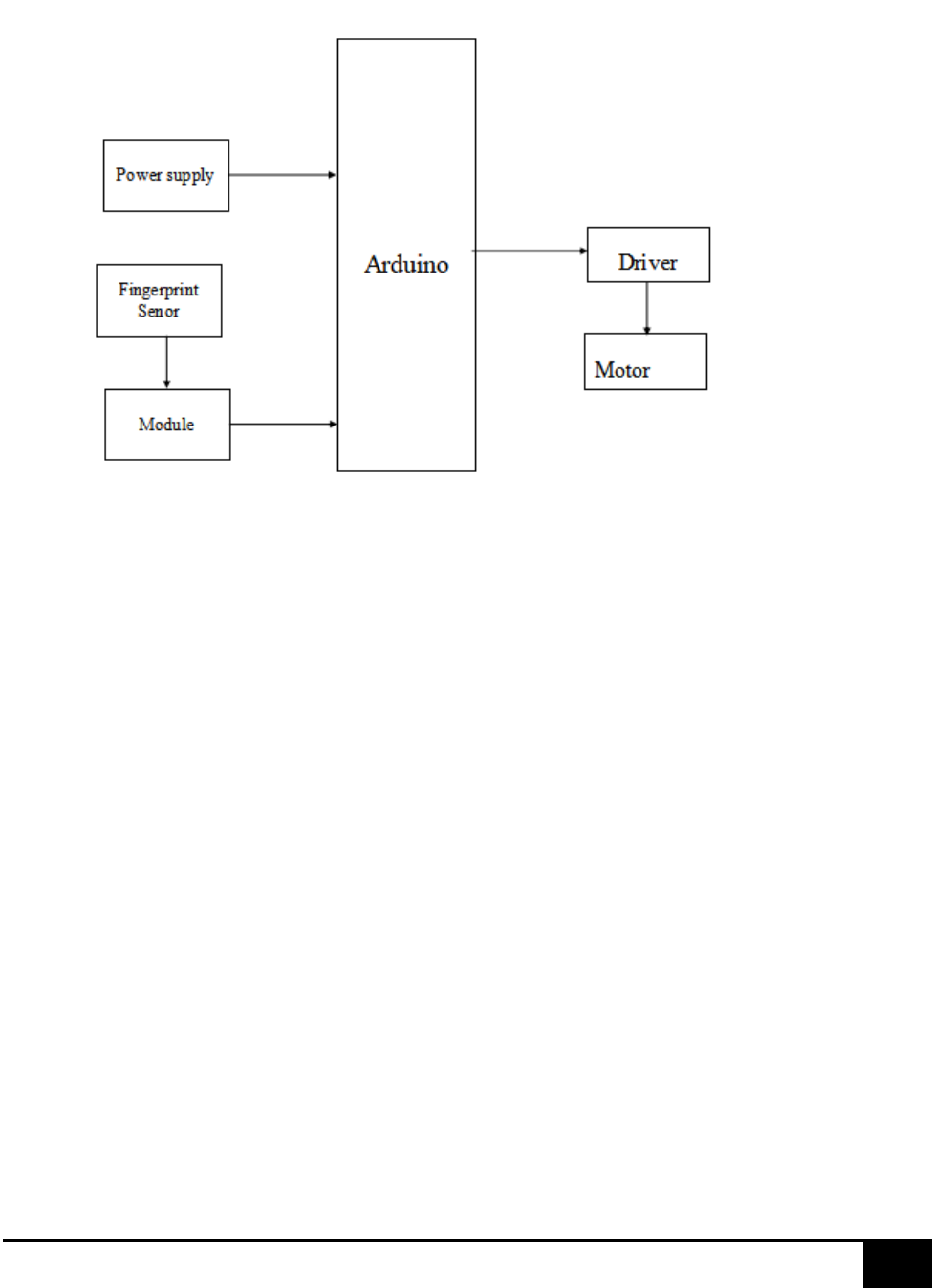
In this project, we are using the finger print sensor, arduino, relay and motor
Thus, we are coming out with this idea so it will make riders more confident and feels
safe.
Moreover, older person usually might have problems when starting their bikes by using
kick starter.
By using this project owner can easily start his motorcycle using fingerprint. Here
owner don’t have to carry key every time.
With our project, that problem will be solved because they would not longer using their
kick starter but they will be using their own fingerprints.
The IOT Technology is used to transmit the sensor data to the webpage by vehicles with
the ultra speed .then these datas are uploaded to the IOT Cloud with the help of Node
MCU.

18
[Date]
ADVANTAGES:
It is highly accurate.
It is unique and can never be the same for two persons.
It is the most economical technique.
It is easy to use.
Use of small storage space.
SENSOR MODULE
All the sensors are connected to the Arduino microcontroller the monitor the driver
status, vehicle theft.
19
[Date]
BLOCK DIAGRAM:
HARDWARE REQUIREMENTS
• Arduino
• Finger print Sensor
• Motor
SOFTWARE REQUIREMENTS
• Arduino IDE
• EMBEDDED C.

20
[Date]
CHAPTER 4
HARDWARE DESIGN
ARDUINO UNO AND ITS PROGRAMMING
Arduino is a tool for making computers that can sense and control more of the physical world
than your desktop computer. It's an open-source physical computing platform based on a simple
microcontroller board, and a development environment for writing software for the board.
Arduino can be used to develop interactive objects, taking inputs from a variety of switches or
sensors, and controlling a variety of lights, motors, and other physical outputs. Arduino projects
can be stand-alone, or they can be communicate with software running on your computer. The
boards can be assembled by hand or purchased preassembled; the open-source IDE can be
downloaded for free.
The Arduino programming language is an implementation of Wiring, a similar physical
computing platform, which is based on the Processing multimedia programming environment.
4.1 Overview
The Arduino microcontroller is an easy to use yet powerful single board computer that has
gained considerable traction in the hobby and professional market. The Arduino is open-source,
which means hardware is reasonably priced and development software is free. This guide is for
students in ME 2011, or students anywhere who are confronting the Arduino for the first time.
For advanced Arduino users, prowl the web; there are lots of resources.
This guide covers the Arduino Uno board (Spark fun DEV-09950, $29.95), a good choice for
students and educators. With the Arduino board, you can write programs and create interface
circuits to read switches and other sensors, and to control motors and lights with very little
effort. Many of the pictures and drawings in this guide were taken from the documentation on
the

21
[Date]
The Duemilanove board features an Atmel ATmega328 microcontroller operating at 5 V with
2 Kb of RAM, 32 Kb of flash memory for storing programs and 1 Kb of EEPROM for storing
parameters. The clock speed is 16 MHz, which translates to about executing about 300,000
lines of C source code per second. The board has 14 digital I/O pins and 6 analog input pins.
There is a USB connector for talking to the host computer and a DC power jack for connecting
an external 6-20 V power source, for example a 9 V battery, when running a program while not
connected to the host computer. Headers are provided for interfacing to the I/O pins using 22
g solid wire or header connectors.
The Arduino programming language is a simplified version of C/C++. If you know C,
programming the Arduino will be familiar. If you do not know C, no need to worry as only a
few commands are needed to perform useful functions.
An important feature of the Arduino is that you can create a control program on the host PC,
download it to the Arduino and it will run automatically. Remove the USB cable connection to
the PC, and the program will still run from the top each time you push the reset button. Remove
the battery and put the Arduino board in a closet for six months. When you reconnect the
battery, the last program you stored will run. This means that you connect the board to the host
PC to develop and debug your program, but once that is done, you no longer need the PC to
run the program.
The Arduino Uno is a microcontroller board based on the ATmega328.It has 14 digital
input/output pins (of which 6 can be used as PWM outputs), 6 analog inputs, a 16 MHz ceramic
resonator, a USB connection, a power jack, an ICSP header, and a reset button. It contains
everything needed to support the microcontroller; simply connect it to a computer with a USB
cable or power it with a AC-to-DC adapter or battery to get started.
The Uno differs from all preceding boards in that it does not use the FTDI USB-to-serial driver
chip. Instead, it features the Atmega16U2 (Atmega8U2 up to version R2) programmed as a
USB-to-serial converter.

22
[Date]
4.2 Summary:
Microcontroller ATmega328
Operating Voltage 5V
Input Voltage (recommended) 7-12V
Input Voltage (limits) 6-20V
Digital I/O Pins 14 (of which 6 provide PWM output)
Analog Input Pins 6
DC Current per I/O Pin 40 mA
DC Current for 3.3V Pin 50 mA
Flash Memory 32 KB (ATmega328) of which 0.5 KB used by bootloader
SRAM 2 KB (ATmega328)
EEPROM 1 KB (ATmega328)
Clock Speed 16 MHz

23
[Date]
4.3 Pin Configuration
The Arduino Uno can be powered via the USB connection or with an external power supply.
The power source is selected automatically.
External (non-USB) power can come either from an AC-to-DC adapter (wall- wart) or battery.
The adapter can be connected by plugging a 2.1mm center-positive plug into the board's power
jack. Leads from a battery can be inserted in the Gnd and Vin pin headers of the POWER
connector.
The board can operate on an external supply of 6 to 20 volts. If supplied with less than 7V,
however, the 5V pin may supply less than five volts and the board may be unstable. If using
more than 12V, the voltage regulator may overheat and damage the board. The recommended
range is 7 to 12 volts.
The power pins are as follows:
• VIN. The input voltage to the Arduino board when it's using an external power source
(asopposed to 5 volts from the USB connection or other regulated power source). You can
supply voltage through this pin, or, if supplying voltage via the power jack, access it through
this pin.
• 5V. this pin outputs a regulated 5V from the regulator on the board. The board can besupplied
with power either from the DC power jack (7 - 12V), the USB connector (5V), or the VIN pin
of the board (7-12V). Supplying voltage via the 5V or 3.3V pins bypasses the regulator, and
can damage your board.
• 3V3. A 3.3 volt supply generated by the on-board regulator. Maximum current draw is 50mA.
• GND. Ground pins.
• IOREF. This pin on the Arduino board provides the voltage reference with which
themicrocontroller operates. A properly configured shield can read the IOREF pin voltage and

24
[Date]
select the appropriate power source or enable voltage translators on the outputs for working
with the 5V or 3.3V.
Memory
The ATmega328 has 32 KB (with 0.5 KB used for the bootloader). It also has 2 KB of SRAM
and 1 KB of EEPROM.
Input and Output
Each of the 14 digital pins on the Uno can be used as an input or output, using pinMode(),
digital Write( ), and digital Read( ) functions. They operate at 5 volts. Each pin can provide or
receive a maximum of 40 mA and has an internal pull- up resistor (disconnected by default) of
20-50 kohms. In addition, some pins have specialized functions:
• Serial: 0 (RX) and 1 (TX). Used to receive (RX) and Trans mit (TX) TTL serial data.
These pins are connected to the corresponding pins of the ATmega8U2 USB-to- TTL Serial
chip.
• External Interrupts: 2 and 3. These pins can be configured to trigger an interrupt on a
lowvalue, a rising or falling edge, or a change in value. See the attach Interrupt () function for
details.
• PWM: 3, 5, 6, 9, 10, and 11. Provide 8-bit PWM output with the analog Write () function.

25
[Date]
• SPI: 10 (SS), 11 (MOSI), 12 (MISO), 13 (SCK). These pins support SPI
communicationusing the SPI library.
• LED: 13. There is a built- in LED connected to digital pin 13. When the pin is HIGH value,the
LED is on, when the pin is LOW, it's off.
The Uno has 6 analog inputs, labeled A0 through A5, each of which provide 10 bits of
resolution (i.e. 1024 different values). By default they measure from ground to 5 volts, though
is it possible to change the upper end of their range using the AREF pin and the analog
Reference () function. Additionally, some pins have specialized functionality:
• TWI: A4 or SDA pin and A5 or SCL pin. Support TWI communication using the Wire
library.
There are a couple of other pins on the board
• AREF. Reference voltage for the analog inputs. Used with analog Reference ().
Reset. Bring this line LOW to reset the microcontroller. Typically used to add a reset
buttonto shields which block the one on the board.

26
[Date]
4.4 Communication
Microcontrollers depend on a host computer for developing and compiling programs. The
software used on the host computer is known as an integrated development environment, or
IDE. For the Arduino, the development environment is based on the open source Processing
platform (www.processing.org) which is described by its creators as a “programming
language and environment for people who want to program images, animation, and
interactions.“ The Arduino programming language leverages an open source project known as
Wiring (wiring.org.co). The Arduino language is based on good old- fashioned C. If you are
unfamiliar with this language, don’t worry; it’s not hard to learn, and the Arduino IDE
provides some feedback when you make mistakes in your programs.
The Arduino Uno has a number of facilities for communicating with a computer, another
Arduino, or other microcontrollers. The ATmega328 provides UART TTL (5V) serial
communication, which is available on digital pins 0 (RX) and 1 (TX). An ATmega16U2 on the
board channels this serial communication over USB and appears as a virtual com port to
software on the computer. The '16U2 firmware uses the standard USB COM drivers, and no
external driver is needed. However, on Windows, a inf file is required. The Arduino software
includes a serial monitor which allows simple textual data to be sent to and from the Arduino
board. The RX and TX LEDs on the board will flash when data is being transmitted via the
USB-to-serial chip and USB connection to the computer (but not for serial communication on
pins 0 and 1).
A Software Serial library allows for serial communication on any of the Uno's digital pins. The
ATmega328 also supports I2C (TWI) and SPI communication. The Arduino software includes
a Wire library to simplify use of the I2C bus; see the documentation for details. For SPI
communication, use the SPI library.
As you go through the list of programming statements available in the Arduino IDE (choose
Help->Reference), you might think there isn’t much power for doing t hings like running
servos, operating stepper motors, reading potentiometers, or displaying text on an LCD. Like
most any language based on C, the Arduino supports the notion of “libraries” code

27
[Date]
Repositories that extend core programming functionality. Libraries let you re- use code
without having to physically copy and paste it into all your programs. The standard Arduino
software installation comes with several libraries you may use, and you can download others
from the Arduino support pages and from third-party websites that publish Arduino library
code. A good example of a library you’ll use with the Robot and likely many other robot
projects is
Servo. This library allows you to connect one or more hobby R/C servos to the Arduino’s digital
I/O pins. The Servo library comes with the standard Arduino installation package Library-
>Servo. This adds the line
#include <Servo.h>
Which tells the Arduino IDE that you wish to include the Servo library in your sketch. With
the functionality of the library now available to you, you can use its various functions to control
one or more servos. For example, you can use the write function to rotate a servo to a specific
position, from 0 to 180 degrees. The following code
myServo.write(90);
Moves a servo to its midpoint, or 90 degree position. Structurally, Arduino sketches are very
straightforward and are pretty easy to read and understand. The Arduino program contains two
main parts: setup () and loop (). These are programming functions that do what their names
suggest: setup () sets up the Arduino hardware, such as specifying which I/O lines you plan to
use, and whether
They are inputs or outputs. The loop () function is repeated endlessly when the Arduino is

28
[Date]
operating.
Arduino IDE (Integrated development environment) is used to write the program and
dump into the Arduino board
29
[Date]
4.5 ARDUINO SOFTWARE:
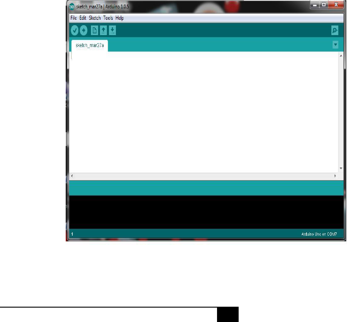
1. Open Arduino IDE as shown below
Open Arduino IDE
30
[Date]
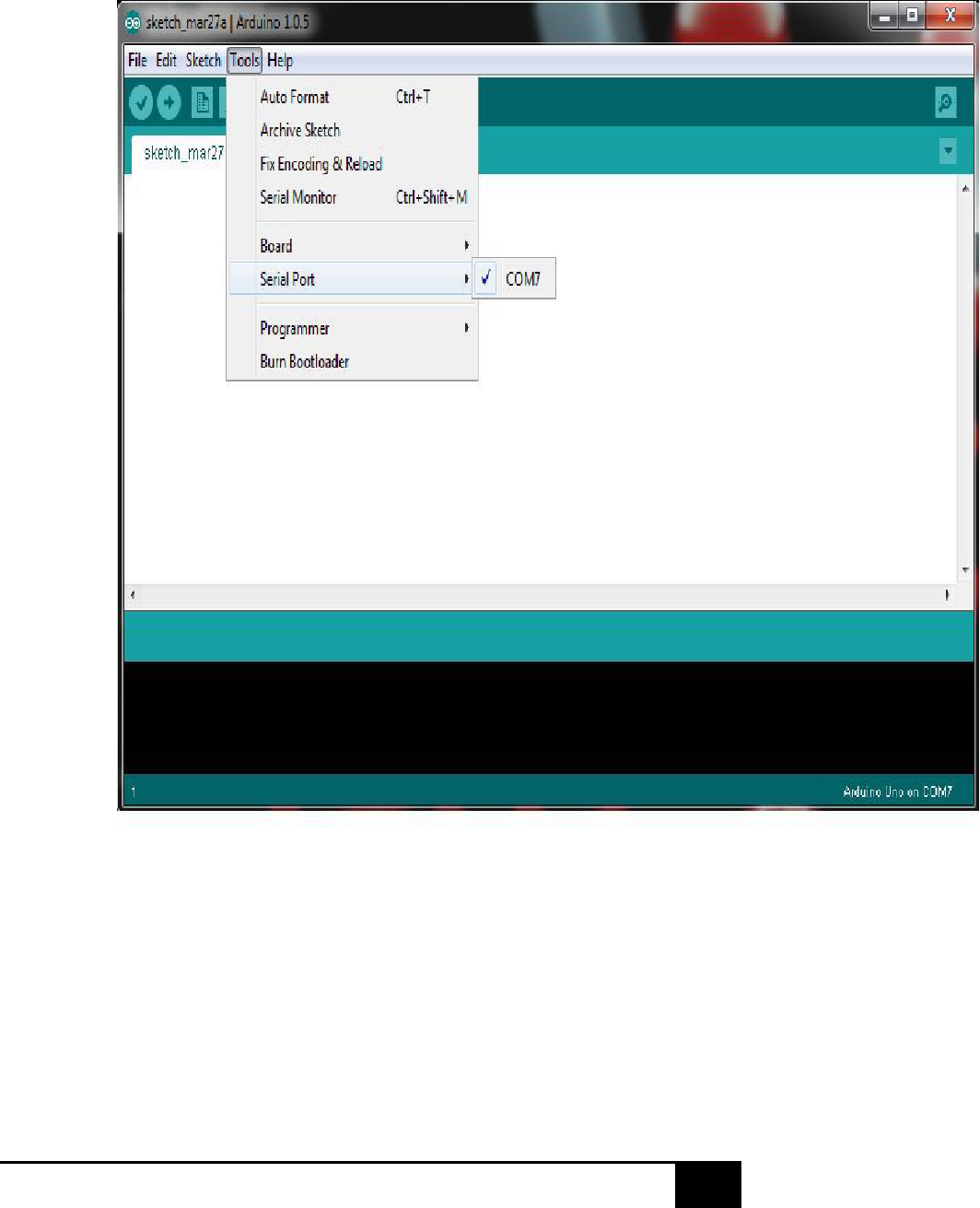
2. Select the COM Port from tool
Select the COM Port

31
[Date]
3. Select the required Arduino board from Tools as
shown below
Select the required Arduino board
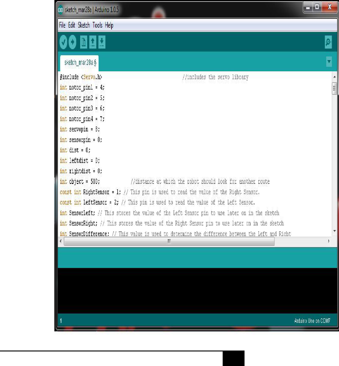
4. Write the sketch in Arduino IDE
32
[Date]
Sketch in Arduino IDE

33
[Date]
4. Compile and upload the Sketch to Arduino boardupload the Sketch to Arduino board

34
[Date]
Finger Print Module
Secure your project with biometrics - this all-in-one optical fingerprint sensor will make adding
fingerprint detection and verification super simple. These modules are typically used in safes -
there's a high powered DSP chip that does the image rendering, calculation, feature-finding and
searching. Connect to any microcontroller or system with TTL serial, and send packets of data to
take photos, detect prints, hash and search. You can also enroll new fingers directly - up to 162
finger prints can be stored in the onboard FLASH memory. We like this particular sensor because
not only is it easy to use, it also comes with fairly straight-forward Windows software that makes
testing the module simple - you can even enroll using the software and see an image of the
fingerprint on your computer screen. But, of course, we wouldn't leave you a datasheet and a "good
luck!" - we wrote a full Arduino library so that you can get running in under 10 minutes. The
library can enroll and search so its perfect for any project (https://adafru.it/aRz). We've also written
a detailed tutorial on wiring and use (https://adafru.it/clz). This is by far the best fingerprint sensor
you can get. Supply voltage: 3.6 - 6.0VDC Operating current: 120mA max Peak current: 150mA
max Fingerprint imaging time Storage capacity: 162 templates Safety ratings (1-5 low to high
safety) False Acceptance Rate
Enrolling vs. Searching
There are basically two requirements for using the optical fingerprint sensor. First is you'll need to
enroll fingerprints - that means assigning ID #'s to each print so you can query them later. Once
you've enrolled all your prints, you can easily 'search' the sensor, asking it to identify which ID (if
any) is currently being photographed. You can enroll using the Windows software (easiest and
neat because it shows you the photograph of the print) or with the Arduino sketch (good for when
you don't have a Windows machine handy or for on-the-road enrolling).
Enrolling New Users with Windows
The easiest way to enroll a new fingerprint is to use the Windows software. The interface/test
software is unfortunately windows-only but you only need to use it once to enroll, to get the
fingerprint you want stored in the module. First up, you'll want to connect the sensor to the
computer via a USB-serial converter. The easiest way to do this is to connect it directly to the
USB/Serial converter in the Arduino. To do this, you'll need to upload a 'blank sketch' this one
works well for "traditional" Arduinos, like the Uno and the Mega
// this sketch will allow you to bypass the Atmega chip

35
[Date]
// and connect the fingerprint sensor directly to the USB/Serial
// chip converter.
// Red connects to +5V
// Black connects to Ground
// White goes to Digital 0
// Green goes to Digital 1
void setup() {}
void loop() {}
If you're using a Leonardo, Micro, Yun, Zero, or other native-USB device like ATSAMD21 or
ATmega32U4-based controller, use the Leo_passthru sketch instead of the "blank" sketch.
//Leo_passthru
// Allows Leonardo to pass serial data between fingerprint reader and Windows.
//
// Red connects to +5V
// Black connects to Ground
// Green goes to Digital 0
// White goes to Digital 1
void setup()
{
// put your setup code here, to run once: Serial1.begin(57600); Serial.begin(57600); }
void loop() { while (Serial.available()) Serial1.write(Serial.read());
while (Serial1.available())
Serial.write(Serial1.read());
}
Wire up the sensor as described in the sketch comments after uploading the sketch. Since the sensor
wires are so thin and short, we stripped the wire a bit and melted some solder on so it made better
contact but you may want to solder the wires to header or similar if you're not getting good contact.
When you plug in the power, you may see the LED blink to indicate the sensor is working.

36
[Date]
If your sensor has all the same-color wires, The first wire from the left is ground, then the two data
pins, then power. You'll have to cut, strip and solder the wires.
RX is the same as the White wire TX is the same as the Green wire If your sensor has different
wires, The first wire from the left should be the black wire ground, then the two data pins, RX is
the white wire, TX is the green wire then the red power wire. You'll have to cut, strip and solder
the wires. And press OK when done. You should see the following, with a blue success message
and some device statistics in the bottom corner. You can change the baud rate in the bottom left
hand corner, as well as the "security level" (how sensitive it is) but we suggest leaving those alone
until you have everything running and you want to experiment. They should default to 57600 baud
and security level 3 so set them if they're wrong

37
[Date]
CHAPTER 5
RESULT AND DISCUSSIONS
This is an optical biometric fingerprint reader/sensor module with TTL UART interface for direct
connections to a microcontroller UART. The user can store the finger print data in the module and
can configure it in 1:1 or 1: N mode for identifying the person. This can be used to authenticate
authorized riders.

38
[Date]

39
[Date]
CONCLUSION
As we all know, these days motor vehicle accident is not an odd incident. Also there is regular
increases in the theft of motor vehicle after the year by year. This finger print base biometric
authentication provides a strong secure authentication of owners and riders. Also it will sent the
location of the vehicle every second and alerts.

40
[Date]
FUTURE SCOPE
We can use solar panel for helmet power supply and this same power supply can be used for
charging our mobile. In future we have a tendency to construct an intelligent system of compact
size. Light dimmer sensors can be used to dim the light automatically when light from other
vehicles fall on it. Government should enforce laws to install such system in each two wheelers.
We can implement various bioelectric sensors on the helmet to measure various activities. We can
use small camera for recording of the driver's activity. It can be used for passing message from
one vehicle to another vehicle by using wireless transmitter. If in a case helmet gets stolen then
bike can be started by the password.
REFERENCES
[1] Mangesh Jadhawar1, Gauri Kandepalli2, Ashlesha Kohade3, Rajkumar Komati4 1,2,3,4MIT
College of Engineering, ENTC Department, Pune
[2] Haran P C and Suriyanarayani R (2012), Embedded System Based Automobile Accident
Prevention, Proc. of the Intl. Conf. on Advances in Computer Science and Electronics Engineering.
[3] SMART HELMET Saravana Kumar K 1, Anjana.B.S 2, Litto.Thomas3, Rahul.K.V 4 1
Associate Professor, Department of Computer Science, Christ University, Bangalore-560029.

41
[Date]
2,3,4 Third year MCA students, Department of Computer Science, Christ University, Bangalore-
560029
