OPERATION and SAFETY MANUAL
LMT Manufactured MRP™ WEAPON SYSTEM
BE A SAFE AND RESPONSIBLE GUN OWNER - BEFORE HANDLING YOUR WEAPON
READ AND UNDERSTAND THE SAFETY INFORMATION INSIDE THIS DOCUMENT
READ AND UNDERSTAND HOW TO OPERATE THIS FIREARM
ALWAYS OPERATE FIREARMS LEGALLY AND SAFELY
ALWAYS STORE ALL FIREARMS SAFELY AND RESPONSIBLY
Lewis Machine & Tool Co.
1305 W. 11
th
St. - Milan, IL 61264 USA
Main: 309.787.7151 – Fax: 309.787.7193
Sales: 309.732.9527 – Fax: 309.787.2636
Email: sales@lmtdefense.com
www.lmtdefense.com
LMT Manufactured MRP™ WEAPON SYSTEM
Information contained in this publication is free of “ITAR” restricted data.
INTRODUCTION AND GENERAL DESCRIPTION

Rev F www.lmtdefense.com Page
2
CONTENTS
Introduction 3
Equipment Identification 4
Nomenclatures 5
Rules for Safe Gun Handling 6
Rules for Safe Gun Handling with Sling 7
Maintenance Before Storage 9
Storage / Transportation 9
Loading / Unloading Firearm 10
Preparation for Firing 13
Sighting Adjustments 14
Ammunition 15
Cleaning and Maintenance 17
Cleaning and Maintenance of Piston System 18
Action of Mechanism 19
Piston System - Modes 20
Trouble Shooting 21
Field Stripping - Assembly ~ Disassembly 22
Function / Operation 30
Limited Warranty 31
Weapon - General Specification 32
Exploded Views of Weapon System
Rifle Assembly 34
Lower, Semi Auto Assembly 35
Lower, Full Auto Assembly 37
Selector Ambi Assembly 39
2 Stage Trigger Assembly 40
Full Auto Trigger Assembly 41
Upper Assembly 42
Upper Receiver Assembly 43
Barrel Assembly (Gas DI) 44
Barrel Assembly (Piston) 45
Charging Handle Assembly 47
Carrier Group Assembly (Gas DI) 48
Carrier Group Assembly (Piston) 49
Carrier Assembly 50
Bolt Assembly 51
Buttstock Assembly 52
Maintenance Tool Kit 53

Rev F www.lmtdefense.com Page
3
THE MRP™ WEAPON SYSTEM IS AN AUTOLOAD FIREARM. DO NOT ATTEMPT TO LOAD, OPERATE
OR FIRE BEFORE READING AND UNDERSTANDING THE SAFETY INFORMATION IN THIS MANUAL.
THE MRP™ WEAPON SYSTEM IS A MAGAZINE FEED CENTERFIRE AUTOLOADING
RIFLE. THE RIFLE WILL CONTINUE TO FIRE EACH TIME THE TRIGGER IS PULLED UNTIL THE RIFLE
IS UNLOADED OR THE AMMUNITION IN THE MAGAZINE HAS BEEN DEPLEATED. IF A CARTRIDGE IS
IN THE CHAMBER, THE WEAPON WILL FIRE EVEN IF THE MAGAZINE IS EMPTY OR THE MAGAZINE
HAS BEEN REMOVED FROM THE FIREARM. THE FIREARM IS EMPTY ONLY WHEN THE CHAMBER IS
EMPTY.
ALWAYS TREAT THIS AND EVERY FIREARM AS IF IT IS LOADED. ALWAYS POINT A
FIREARM IN A SAFE AND RESPONSIBLE DIRECTION.
THIS MANUAL DOES NOT PROVIDE INSTRUCTION ON SELF DEFENSE, HUNTING CUSTOMS AND OR
PRACTICES OR COMPETITIVE SHOOTING. THE NRA, LOCAL DEALERS OR SHOOTING
ASSOCIATIONS CAN PROVIDE INFORMATION REGARDING TRAINING COURSES FOR THESE
ACTIVITIES.
Your children should be shown “The NRA Eddie Eagle” video, on what to do if they find a firearm. The video is
available by calling the NRA at (703) 267-1000
INTRODUCTION
The weapon is magazine fed, gas or piston operated, having a single shot, semi-automatic, and optional full
automatic fire capability.
MRP™ WEAPON SYSTEM
Primary sight. Detachable Iron Sight System (DISS) comprising of a tactical front and rear sight system, both
mounted on the upper MIL-STD-1913 rail.
EQUIPMENT IDENTIFICATION
The weapons and individual items are identified as follows:
• LM308MWS, Rifle (Gas – Direct Impingement)
• CQB, Rifle (Gas – Direct Impingement)
• CQBP, Rifle (Piston)
• Detachable Iron Sight System (DISS)
o Tactical Front Sight
o Tactical Rear Sight (NSN 1005-01-548-5193)
o Detachable Carry Handle Assembly (optional)

Rev F www.lmtdefense.com Page
4
LMT Manufactured MRP™ Weapon System firearms are reliable and safe to use when the firearm safety rules
are followed. There are a number of internal safety mechanisms within the internal mechanism of the firearm
which ensure that the firearm will not discharge unless the trigger of the firearm is pulled. NEVER RELY ON
MECHANICAL FEATURES ALONE. Only your safe gun-handling habits will ensure the safe use of your
firearm. This is your responsibility. That is one reason why it is important to never modify or alter your firearm.
Before you use your firearm, you should be fully familiar with its operations.
Here is a list of basic firearms terminology.
AMMUNITION – CENTERFIRE – Is described as ammunition which contains the primer in the center of the
base of the case. Among the most common centerfire firearm cartridges are the .204 Ruger, .223, 5.56 NATO,
.243, .260, 6.8 SPC, .308 Win, and 7.62 NATO.
BOLT – The mechanism that houses the firing pin, ejector and extractor.
CALIBER – The diameter of a bullet, designated in hundredths or thousandths of an inch (.223) or in
millimeters (5.56MM).
CHARGING HANDLE – This moves the bolt carrier group which cocks the firearm when preparing to fire or
allows access to the bolt and chamber to verify that the weapon is either loaded or clear of ammunition.
COMPENSATOR – This may reduce a portion of the recoil, depending on model and configuration applied to
the weapon as well as suppress muzzle flash.
HANDGUARD – This is a protective shield that covers the gas tube and the barrel keeping your hand from the
hot barrel.
LOWER RECEIVER – Lower part of the rifle containing the receiver, trigger and associated parts.
RIFLE – A weapon that can be fired from the shoulder.
SAFETY SELECTOR LEVER – This feature changes the trigger between the safe mode and the firing modes.
UPPER RECEIVER – The part of the receiver containing the barrel, sights, bolt and associated parts.
The operation of your firearms will be explained in greater detail in the pages that follow, as well as, a
broader description of key component parts.

Rev F www.lmtdefense.com Page
5
NOMENCLATURE
Buttstock Assy Rear Sight Assy Brass Deflector Upper Receiver Barrel Assy
Stock Release Lever Takedown Pin Trigger Magazine Release
Charging Handle Forward Assist Bolt Carrier Front Sight
Pistol Grip Trigger Guard Locking Screws
Gas Piston Plug
Quick Detachable Sling Mounts Pivot Pin Bolt Catch Safety Selector
Magazine Front Sight Compensator
Serial Ambidextrous Bolt Catch
Number Magazine
Release
LM308MWS, Rifle
(Gas-Direct Impingement)
Ambidextrous
Safety Selector
Lever
CQB, Rifle
(Gas-Direct Impingement)
CQB, Rifle
(Gas-Piston)

Rev F www.lmtdefense.com Page
6
RULES FOR SAFE GUN HANDLING
To safely and properly handle this firearm, you must understand that injury or death to you or others may
result from unsafe or careless use.
It must be kept in mind that while the general rules of safe gun handling always apply, circumstances or
conditions may exist that require additional precautions to be taken.
• Always keep the muzzle pointed in a safe direction
• Treat every gun as if it were loaded
• Load your firearm only when ready to fire the weapon
• Keep the safety on until ready to fire
• Keep your finger off of and away from the trigger until you are going to shoot the weapon
• Move the safety from “Safe” to “Fire” only when ready to shoot
• Fire the weapon only when you are sure of your target and backstop
• Do not fire the weapon if unsure where the bullet will travel if the backstop is penetrated
• Always keep the muzzle pointed in a safe direction
• Never rely on a mechanical safety as a replacement or substitute for safe gun handling
• Even if you have handled and or fired an autoloading firearm before; practice inserting and removing
an empty magazine to become accustomed to the weapon handling characteristics.
Always keep the barrel free of obstructions, dirt, mud, sand and other debris.
If you suspect that the barrel of the firearm may be obstructed, unload the firearm, examine the bore and
remove any obstruction and clean before reloading and firing the weapon. An obstructed barrel may burst,
destroying the firearm and seriously injuring the shooter and any bystanders.
When moving over, under or on any obstacle, always maintain control of the muzzle direction. Unload the
firearm if there is any chance that you might fall and or lose control of the muzzle direction.
To avoid an accidental discharge, always keep the chamber empty until ready to fire.
Guns, alcohol or drugs don’t mix. Shooting while your senses, judgment and or coordination are impaired may
cause serious injury or death to the shooter and or bystander.
THE FIREARM IS UNLOADED ONLY WHEN THE MAGAZINE IS REMOVED AND THE
CHAMBER IS EMPTY. TREAT EVERY FIREARM AS IF IT IS LOADED.
DO NOT HAND A LOADED FIREARM TO ANOTHER PERSON. UNLOAD IT FIRST TO PREVENT AN
ACCIDENTAL DISCHARGE.
When handing or transferring a firearm to another person or accepting a firearm from another person,
ALWAYS inspect the firearm; open the action and inspect the chamber to verify that the firearm is unloaded.
EVERY TIME
When removing a firearm from a case or sleeve, always open the action and inspect the chamber to verify it is
unloaded and not obstructed. EVERY TIME
Always point the gun in a safe direction when loading and unloading the firearm.
Always unload your firearm before cleaning.
There is no way to predict which direction bullets will travel or ricochet when fired at flat
ground surfaces or water. When present, always fire directly into a sufficient backstop.
Always wear eye and ear protection when using a firearm.
Discharging a firearm in a building, home or apartment always causes property damage,
injury and/or death. Centerfire firearm bullets can penetrate several floors and/or walls within a structure that
the firearm was discharged in and travel to undisclosed destinations. This can and/or will cause property
damage, injury and/or death.

Rev F www.lmtdefense.com Page
7
CAUTION !..
RULES FOR SAFE GUN HANDLING WHEN UTILIZING A SLING
• Use only slings that will adequately support the firearm and safely control the muzzles direction
• If a sling is to be used, unload the firearm and practice pulling it on and off, moving with the firearm on
foot, in a vehicle (if legal in your application) or using in various firing positions
• If a sling is to be used with a vest, packs, etc., unload the firearm and practice pulling it on and off,
moving with the firearm on foot, in a vehicle (If legal in your application) or using in various firing
positions
• Always unload a firearm when installing, adjusting or removing a sling or similar item
YOUR SAFETY RESPONSIBILITIES - SAFETY IS YOUR NUMBER ONE RESPONSIBILITY!
SAFE GUN HANDLING IS YOUR PERSONAL RESPONSIBILITY AT ALL TIMES. Firearms are dangerous
and can cause serious injury or death if they are misused. Safety must be the prime consideration of anyone
who owns or handles firearms. Accidents are the result of violating the rules of safe gun handling and common
sense. Firearms safety training is available. Contact your dealer, law enforcement agency, local sportsman’s
club, etc. for availability.
At home, in the field, at the range, or anywhere, the first concern of every firearm owner should be safety.
Apply the following safety rules in every situation, with any kind of firearm. If you feel uncertain about any
operational aspects of your firearm, please contact Lewis Machine & Tool Co. customer service (309)
732.9527 before proceeding with its operation.
YOU MUST FOLLOW ALL OF THESE SAFETY RULES TO ENSURE THE SAFE USE OF
YOUR FIREARM. THE FAILURE TO FOLLOW THESE BASIC FIREARM SAFETY RULES MAY RESULT IN
AN UNINTENDED DISCHARGE WHICH COULD CAUSE SERIOUS PERSONAL INJURY OR DEATH TO
YOU OR OTHERS.
ALWAYS KEEP YOUR FIREARM POINTED IN A SAFE DIRECTION. Never point a firearm at anyone or
anything you do not intend to shoot regardless of whether or not it is loaded. This is particularly important
when loading, unloading, or field stripping the gun. ALWAYS control the direction of the firearm.
ALWAYS TREAT EVERY FIREARM AS IF IT IS LOADED AND WILL FIRE IF THE TRIGGER IS PULLED.
Do not take anyone’s word that the firearm is unloaded – always check for yourself. Never pass your firearm to
another person until the action is open and you visually check that it is unloaded. Keep your firearm unloaded
and safely stored when not in use.
NEVER PLACE YOUR FINGER INSIDE THE TRIGGER GUARD OR ON THE TRIGGER UNLESS YOU
INTEND TO FIRE THE WEAPON. Ensure that other objects not touch the trigger.
ALWAYS BE SURE OF YOUR TARGET AND WHAT IS BEYOND IT. Always be sure of where the bullet will
strike and shoot only where there is a safe back stop free of obstructions, water or other surfaces which can
cause ricochets. Do not fire into the sky.
NEVER CROSS OBSTACLES SUCH AS FENCES OR STREAMS WITH A LOADED FIREARM.
FIREARM SECURITY IS YOUR RESPONSIBILITY. You must secure firearms safely from children and
unauthorized users. Your firearm should always be kept unloaded and locked when not in use. A lock can be
purchased from several sources for this purpose. Never assume that the use of this lock is sufficient to safely
secure your firearm. You must always evaluate your personal situation and employ the security system(s) that
meets your needs and prevents children and unauthorized users from gaining access to your firearm.
APPROPRIATE USE FOR YOUR FIREARM MEANS USING YOUR FIREARM FOR LEGAL PURPOSES.
It is your responsibility to ensure that you are in compliance with all applicable laws and regulations regarding
the use of your firearm.
NEVER RELY ON MECHANICAL FEATURES ALONE. Mechanical features may fail. Only your safe gun-
handling habits will ensure the safe use of your firearm. This is your responsibility.
ALWAYS SAFELY STORE AND SECURE YOUR FIREARM. Safe and secure storage of your firearm is one
of your most important responsibilities. It is a full-time responsibility. You must always secure your firearm and
ammunition separately so that they are not accessible to children and/or other unauthorized persons.

Rev F www.lmtdefense.com Page
8
NEVER KEEP AMMUNITION IN THE SAME LOCATION AS THE FIREARM. Store each in a separate and
secure place.
ALWAYS WEAR EYE AND EAR PROTECTORS THAT ARE SPECIFIED FOR FIREARM USE
EVERY TIME YOU DISCHARGE YOUR FIREARM. Make sure others in the vicinity of where you will be
shooting do so as well.
NEVER USE ALCOHOL OR DRUGS BEFORE OR WHILE SHOOTING. Do not use your firearm if you are on
any medication which impairs, even slightly, your mental or physical ability.
ALWAYS HAVE ADEQUATE VENTILATION. Discharging firearms, cleaning firearms, or handling ammunition
in poorly ventilated areas may result in exposure to lead and other substances known to cause birth defects,
reproductive harm, and other serious physical injury. Review the warnings and labels for all ammunition and
cleaning products carefully. Wash hands thoroughly after exposure.
BEFORE HANDLING ANY FIREARM, UNDERSTAND ITS OPERATION. Not all firearms are the same.
Familiarize yourself with the mechanical features of any firearm you intend to use. If you feel uncertain about
any operational aspects of your firearm, please contact Lewis Machine & Tool Co. customer service at (309)
732.9527 before proceeding with its operation.
NEVER ALLOW A FIREARM TO BE USED BY INDIVIDUALS WHO DO NOT UNDERSTAND ITS SAFE
OPERATION OR HAVE NOT READ THESE FIREARM SAFETY RULES.
ALWAYS USE THE CORRECT AMMUNITION FOR YOUR PARTICULAR FIREARM AS INDICATED BY THE
MARKING ON THE FIREARM.
NEVER USE NON-STANDARD, RELOADED OR “HAND-LOADED” AMMUNITION.
BE SURE ALL ACCESSORIES ARE COMPATIBLE WITH THE FIREARM AND THAT THE ACCESSORIES
DO NOT INTERFERE WITH SAFE OPERATION.
NEVER DISASSEMBLE YOUR FIREARM BEYOND THE FIELD STRIPPING PROCEDURE OUTLINED IN
THIS MANUAL. Improper disassembly or reassembly of your firearm may be dangerous and can lead to
serious injury or death.
NEVER MANIPULATE, ADJUST OR CHANGE ANY OF THE INTERNAL COMPONENTS OF YOUR
FIREARM. Improper manipulation of any internal component may affect the safety and reliability of your
firearm and may cause serious injury or death.
NEVER ALLOW ANY ALTERATION OR REPLACEMENT OF PARTS IN YOUR LEWIS MACHINE & TOOL
CO. FIREARM UNLESS PERFORMED BY A QUALIFIED GUNSMITH USING GENUINE LEWIS MACHINE &
TOOL CO. PARTS. If you do otherwise, improper functioning of your firearm may occur and serious injury or
death may result.
SAFE USE OF A FIREARM IS YOUR PERSONAL RESPONSIBILITY AND THE FAILURE
TO FOLLOW ALL OF THESE BASIC SAFETY RULES MAY RESULT IN SEVERE PERSONAL INJURY OR
DEATH TO YOU OR OTHERS. You are the most important safety device when it comes to the use of your
firearm.
LEWIS MACHINE & TOOL CO. WILL NOT BE RESPONSIBLE FOR ANY PERSONAL INJURY, DEATH OR
PROPERTY DAMAGE THAT RESULTS FROM: (1) THE CRIMINAL OR NEGLIGENT USE OF THIS
FIREARM; (2) A DISREGARD OF THESE SAFETY INSTRUCTIONS AND WARNINGS; (3) IMPROPER OR
CARELESS HANDLING OF THIS FIREARM; (4) THE USE OF A NON-STANDARD, DEFECTIVE,
IMPROPER OR RELOADED AMMUNITION; AND (5) IMPROPER OR NEGLIGENT MODIFICATIONS OR
REPAIRS TO THE FIREARM.

Rev F www.lmtdefense.com Page
9
MAINTENANCE BEFORE STORAGE
When storing, do not encase your firearm in anything that will attract or hold moisture, for example, leather or
heavy cloth. Also, do not store guns with a plug inserted in the barrel for this can be a contributing factor to
moisture accumulation. If your firearm is to be stored for an extended period, the bore, the chambers and
internal working mechanism should be oiled with a high quality lubricating oil or preservative intended for
firearms. The external working mechanisms, lower and upper receiver, and barrel should be coated with anti-
rust oil. Before using your firearm again, be sure to clean it. If wear is noted, do not use the firearm. Return it
to Lewis Machine & Tool Co. for service or have it checked by a qualified gunsmith.
SAFE STORAGE & TRANSPORTATION
FIREARMS ARE DANGEROUS WHEN USED AND STORED IMPROPERLY. THEY POSE
A RISK OF SERIOUS OR FATAL INJURIES. FIREARMS CAN BE ESPECIALLY DANGEROUS TO
CHILDREN WHEN THEY ARE STORED IN AN IRRESPONSIBLE AND UNSAFE MANNER. FOR YOUR
SAFETY AND THE SAFETY OF OTHERS, IT IS IMPERATIVE THAT YOU KEEP YOUR FIREARM LOCKED
AND UNLOADED IN A SECURE PLACE. THE AMMUNITION SHOULD BE STORED IN A SEPARATE,
SECURE LOCATION WHEN IT IS NOT IN USE. SAFE AND SECURE STORAGE OF YOUR FIREARM IS
ONE OF THE MOST IMPORTANT RULES OF FIREARM SAFETY. YOUR FAILURE TO FOLLOW THESE
RULES MAY RESULT IN SERIOUS INJURY OR DEATH TO YOU OR OTHERS.
ALWAYS SECURE YOUR FIREARM IN A MANNER THAT WILL PREVENT UNAUTHORIZED ACCESS.
Whenever your firearm is not in use, keep it unloaded and locked. Your safety and the safety of others require
that you always secure and store your firearm in a manner that will prevent unauthorized access. Never leave
a firearm unattended unless it is locked.
ALWAYS USE A LOCK TO SECURE YOUR FIREARM. BY PURCHASING THIS FIREARM YOU HAVE
ACCEPTED THE RESPONSIBILITY OF SAFELY SECURING THE FIREARM AT ALL TIMES AND
PREVENTING ITS UNAUTHORIZED USE. Never assume that the use of a lock alone is sufficient to safely
secure your firearm. It is your personal responsibility to select and use whatever measures or practices that
will enable you to be absolutely certain that your firearm is secure at all times. A lock, when properly used, can
be an effective tool in preventing unauthorized access to your firearm. There are alternative locks and safe
storage containers available in the marketplace which may also be appropriate for your particular needs.
Consult your local weapon dealer, hardware store, or local police department for guidance on the variety of
other safe storage devices or practices which may be appropriate for your particular needs. Please read and
follow the instructions provided with the lock and or storage device that you have purchased to secure your
firearm.
NEVER LOCK A LOADED FIREARM AND NEVER LOAD A LOCKED FIREARM!!
NEVER ASSUME THAT A “HIDING” PLACE IS A SECURE STORAGE METHOD. Others may be aware of
your storage location or come upon it by chance. It is your personal responsibility to use common sense when
storing your firearm and ammunition and to always make sure they are not accessible to children or other
unauthorized persons.
NEVER TRANSPORT A LOADED FIREARM. When transporting your firearm, be sure it is unloaded and
locked. Safe and secure transportation of your firearm is your responsibility.
ALWAYS FOLLOW THE LAW! Many jurisdictions have laws that make it a crime to keep a firearm unlocked
and in an area accessible to children or others. You must be familiar with all local, state, and federal laws
regarding the safe storage and transportation of your firearm. Failure to know and follow the law may result in
unauthorized access or use of your firearm by another. Obey all laws relating to the storage and transportation
of firearms. Your local police department or weapon dealer can furnish you with available information on
storing and/or transporting a firearm safely and legally.
YOUR FIREARM IS YOUR RESPONSIBILITY. You must prevent your firearm from being stolen or from
being used by untrained or unqualified individuals. Keep it locked, unloaded and secured when not in use.
Rev F www.lmtdefense.com Page
10
BEWARE OF DANGEROUS CONDITIONS
• Be sure Cam Pin is installed in the Bolt Group. If it isn’t, your firearm can still fire and COULD
MALFUNCTION, CAUSING PROPERTY DAMAGE, PERSONAL INJURY OR DEATH.
• When using a Blank Firing Attachment, never fire anything except blank ammunition! For your
safety, we recommend the visible, LMT™ blank firing system that includes a special magazine, barrel
and barrel bullet trap.
• If your firearm stops firing with a live round in the chamber of a hot barrel (a misfire). REMOVE THE
ROUND FAST! However, if you cannot remove it within 10 seconds, remove magazine and wait 15
minutes with the firearm pointing in a safe direction! This way you won’t be hurt by a possible
round “cooking off” (i.e. the round detonating just from the heat of the barrel). Keep your face away
from the ejection port while clearing a hot chamber.
• If your bolt fails to unlock, and you try to free it by tapping the buttstock on the ground while pulling on
the charging handle, keep yourself clear of the Muzzle and the Firearm pointed down range.
• If there is water in the barrel, do not fire the firearm. IT COULD MALFUNCTION CAUSING
PROPERTY DAMAGE, PERSONAL INJURY OR DEATH.
• Pull the charging handle to the rear to break the seal to ensure the water will run off from the chamber
through the ejection port area.
• If a noticeable difference in sound or recoil is experienced, STOP FIRING! Either condition could
indicate an incomplete powder burn and or bullet or other obstruction stuck in the bore of the barrel.
• If a bullet is lodged and can be removed by pushing it out with a cleaning rod, clean any unburned
powder grains from the bore, chamber, and mechanism before resuming shooting. If the bullet cannot
be dislodged by firmly tapping it with a cleaning rod, take the weapon to a qualified gunsmith or
armourer and have the obstruction removed.
• NOTE: With the Bolt Carrier Assembly locked to the rear, or in its forward position, if the firearm is
dropped or jarred with a loaded magazine in place, a live round could be chambered.
ALWAYS PRACTICE SAFE GUN HANDLING.
Use only serviceable and authorized ammunition
Inspect ammunition for defects prior to loading magazines
LOADING THE MAGAZINE
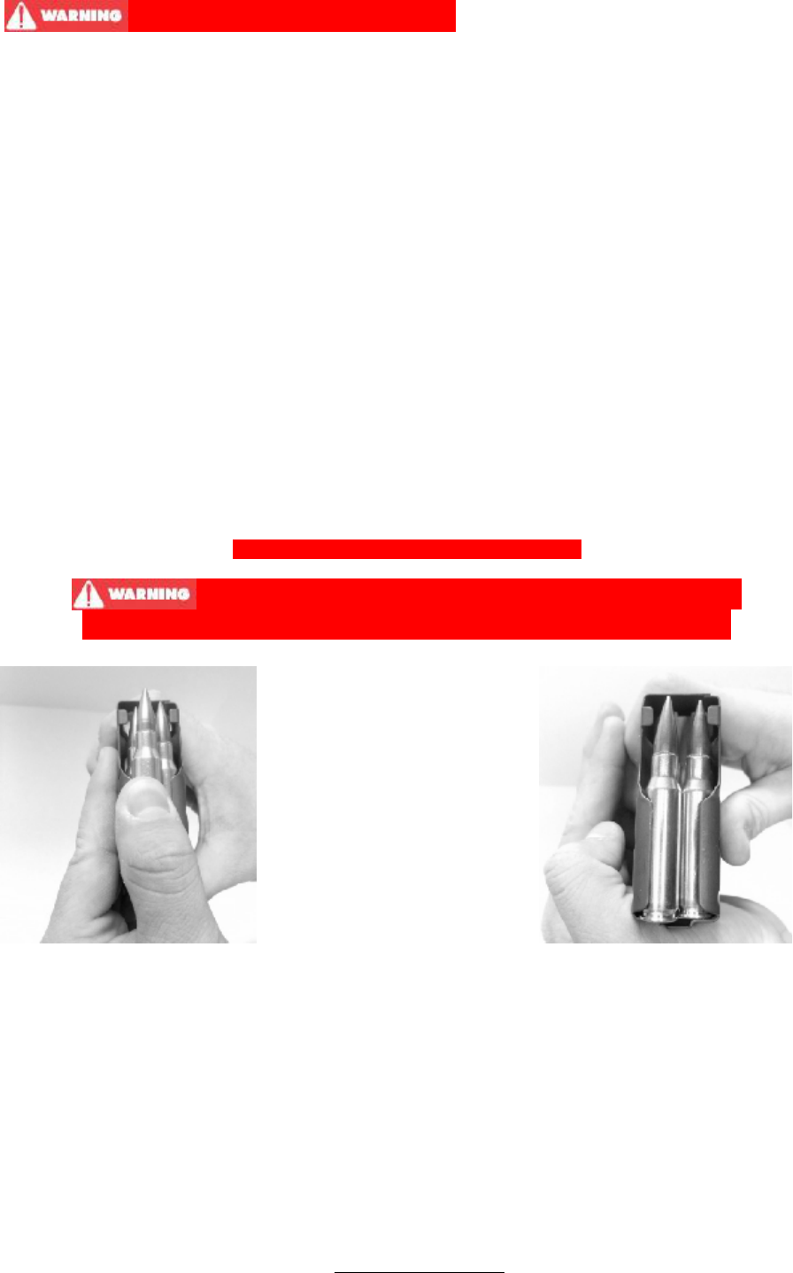
• Load magazines one round at a time.
• Place each round on top of follower, between magazine lips and push down and through until round
rotates under feed lips. Never load more than the amount of rounds the magazine is designed for.
• As rounds are pushed down, slide them to the rear of the magazine.
UNLOADING THE MAGAZINE
• Strip one round at a time out of the magazine by pushing on the cartridge rim. Do not bend or deform
magazine lips when stripping rounds from magazine.
• An alternative method is to push the top round slightly forward and depress the base of the second
round under it. This relieves the pressure on the top round, making it easier to remove from the
magazine.
Rev F www.lmtdefense.com Page
11
LOADING RIFLE AND FIRING
• THIS FIREARM MAY DISCHARGE ACCIDENTALLY WHEN A ROUND IS FED
INTO THE CHAMBER. IF IT IS DROPPED OR RECEIVES A BLOW TO THE MUZZLE OR FRONT
OF THE GUN. (This can occur regardless of the position of the hammer or any of the various
safety devices.) Therefore, extra care and strict adherence to these instructions by the firearm
user is mandatory for minimizing the risk of accidents.
• ALWAYS READ AND UNDERSTAND SAFETY INSTRUCTIONS BEFORE LOADING AND FIRING
YOUR FIREARM.
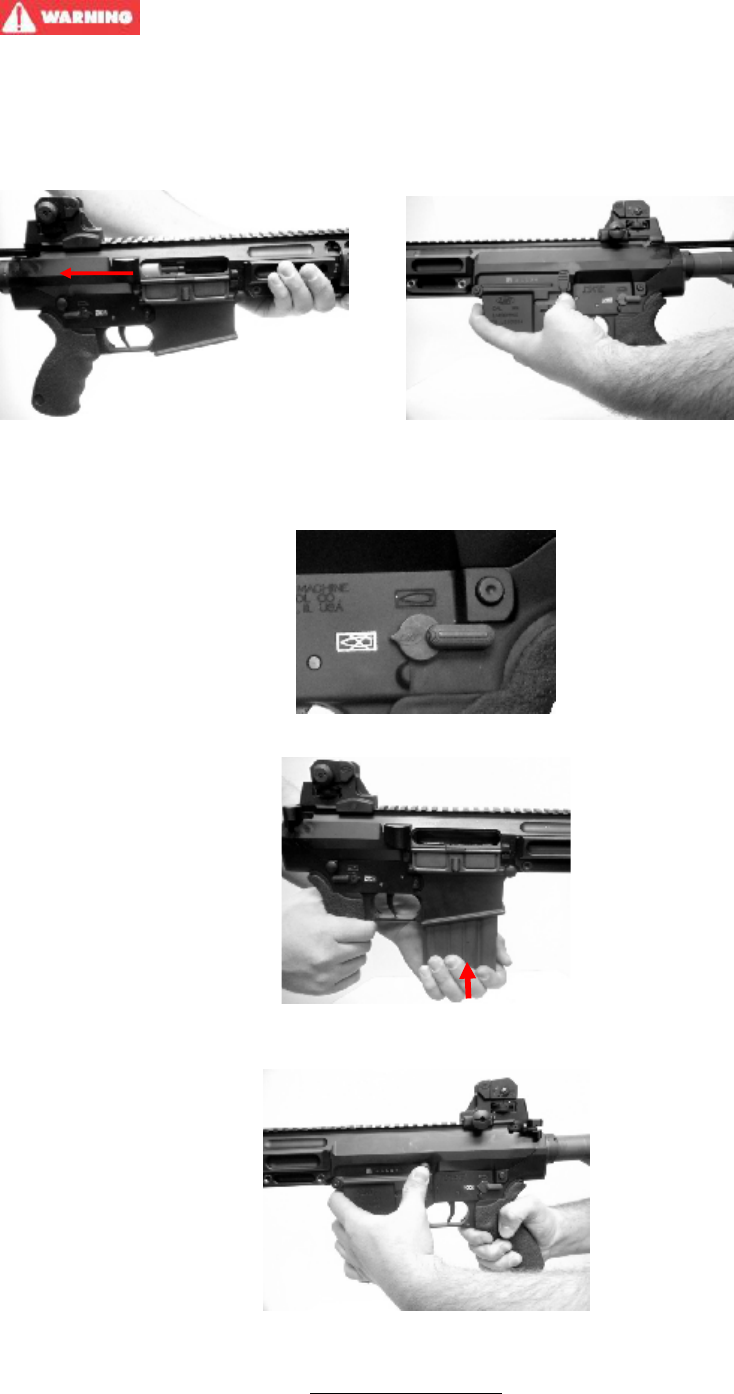
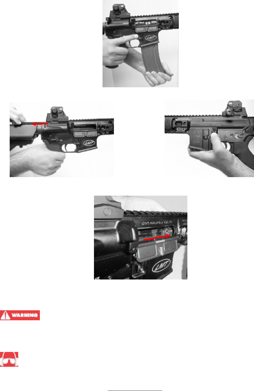
• Point rifle in a safe direction. Pull the bolt fully to the rear with the charging handle and lock the bolt to
the rear with bolt catch.
• Push the charging handle forward until it locks in place.
• Place safety in “SAFE” position and visually check chamber and receiver area.
• Insert loaded magazine well until the magazine catch engages and positively retains magazine. Slap
bottom of magazine with palm of hand to be sure.
• Push on upper portion of bolt catch to release bolt. Bolt will spring forward into battery and load first
round into chamber.

Rev F www.lmtdefense.com Page
12
Fire Selection – Semi Automatic Fire Selection – Full Automatic
(Optional)
- Rifle is now loaded. Keep it pointed in a safe direction
If you rotate the safety from “SAFE” to “FIRE” position…
THE RIFLE WILL FIRE WHEN YOU PULL THE TRIGGER
• THIS IS AN AUTOLOADING FIREARM AND IS IMMEDIATELY LOADED AND
READY TO FIRE AGAIN AFTER EACH SHOT UNTIL THE CHAMBER IS EMPTY.
• If your firearm stops firing with a live round in the chamber of a hot barrel (a
misfire). REMOVE THE ROUND FAST! However, if you cannot remove it within 10 seconds,
remove the magazine and wait 15 minutes with the firearm pointing in a safe direction! This
way you won’t be hurt by a possible round “cooking off” (i.e. the round detonating just from
the heat of the barrel). Keep your face away from the ejection port while clearing a hot
chamber. If firing pin indent on primer is light, misaligned or nonexistent, have your firearm
examined by a competent gunsmith or armourer. If the firing pin indent on primer appears
normal (in comparison with previously fired rounds) assume faulty ammunition; segregate
misfired rounds from other live ammunition and empty cases; reload firearm and carry on
firing.
UNLOADING RIFLE
• ALWAYS UNLOAD YOUR FIREARM IMMEDIATELY AFTER USE AND PRIOR TO
CLEANING AND STORAGE TO MINIMIZE THE RISK OF ACCIDENTAL DISCHARGE.
• ALWAYS READ AND UNDERSTAND SAFETY INSTRUCTIONS BEFORE UNLOADING YOUR
FIREARM.
• Point rifle in safe direction.
Rev F www.lmtdefense.com Page
13
• Rotate safety to the “SAFE” position if possible. (If hammer is not cocked, safety cannot be rotated to
“SAFE”.)
• Remove magazine by pushing in magazine catch button while pulling magazine from receiver.
• Pull charging handle fully to the rear and lock bolt to the rear by pressing on the lower portion of the
bolt catch. If not done so already place safety on “SAFE”.
• Inspect chamber and inside of receiver areas for cartridge or brass. Remove any round and other
debris. Let the bolt go forward and close the dust cover.
PREPARATION FOR FIRING
THE FAILURE TO FOLLOW FIREARM SAFETY REQUIREMENTS WILL CAUSE
SERIOUS PERSONAL INJURY OR DEATH TO YOU OR OTHERS. ALWAYS TREAT ALL FIREARMS AS IF
THEY WERE LOADED. ALWAYS BE SURE THAT THE ACTION OF FIREARMS ARE OPEN, THAT
CHAMBERS ARE CLEAR OF CARTRIDGES, MAGAZINES ARE REMOVED, AND THAT FIREARMS ARE
POINTING IN A SAFE DIRECTION.
ALWAYS WEAR ADEQUATE AND PROPER EAR PROTECTORS SPECIFIED FOR FIREARM USE
TO PREVENT PERMANENT DAMAGE TO YOUR HEARING. Make sure others who are nearby are wearing
ear protection as well.
Rev F www.lmtdefense.com Page
14
ALWAYS WEAR SAFETY GLASSES SPECIFIED FOR FIREARMS USE, WHETHER INDOORS OR
OUT. Safety glasses should protect your eyes from the firing flash and particles associated with the discharge
of ammunition. Failure to do so creates a risk of personal injury from particle or debris spitting or ricochets.
ALWAYS BE ALERT AND ALWAYS FOLLOW THE SAFETY INSTRUCTIONS OF THE RANGE OFFICER.
NEVER SHOOT IF YOU ARE TIRED, COLD OR IMPAIRED IN ANY WAY.
ALWAYS BE AWARE OF OTHER PEOPLE AND MOVABLE OBJECTS IN YOUR SURROUNDING AREA SO
THAT THEY DO NOT ACCIDENTALLY WALK INTO THE LINE OF FIRE.
THE SHOOTER (AND ALL OTHERS IN THE SHOOTING AREA) MUST ALWAYS BE IN A POSITION THAT
IS OUT OF THE LINE OF FIRE AND ARE NOT WITHIN AN AREA WHERE THEY MAY BE STRUCK BY
RICOCHETS, PARTICLE SPITTING FROM A FIREARM, OR BY EJECTED CASES FROM OTHER TYPES
OF FIREARMS.
NEVER USE ALCOHOL OR DRUGS BEFORE OR WHILE SHOOTING.
SIGHT ADJUSTMENT
The MRP™ Weapon System uses a Detachable Iron Sight System (DISS). Some models are equipped with a
fixed adjustable front sight and Tactical Rear Sight. These systems do not allow the removal of the Adjustable
Front Sight.
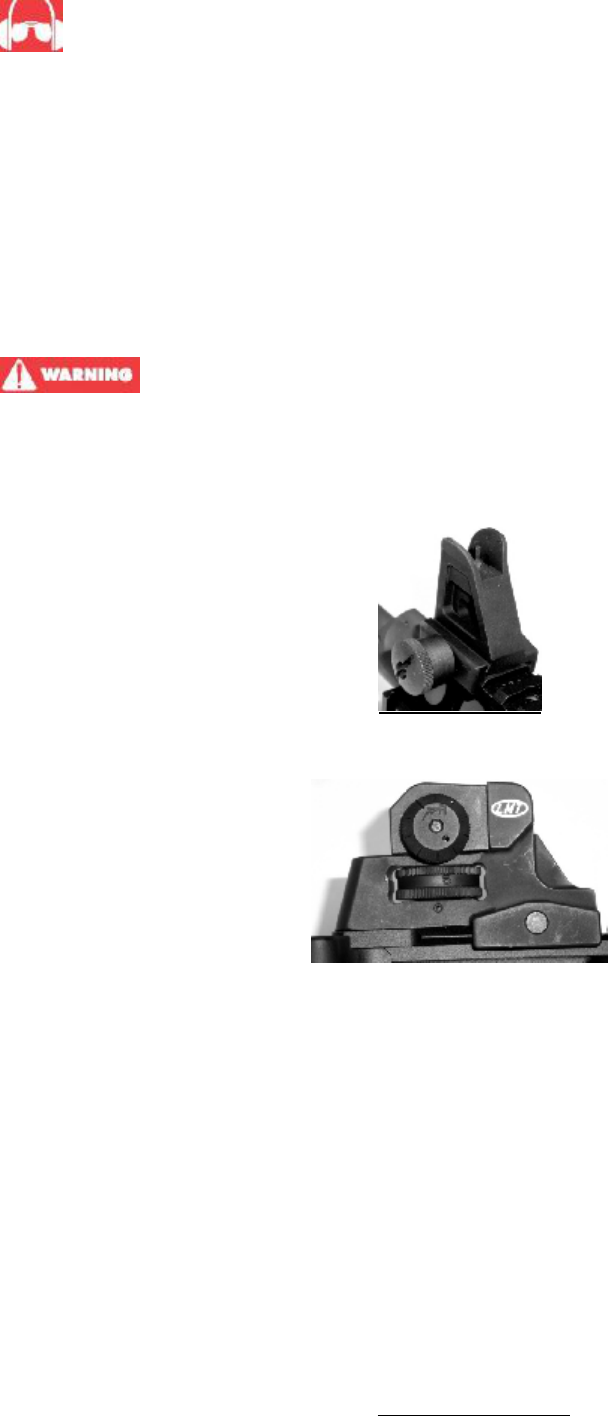
TACTICAL FRONT SIGHT – The front site post is moved up or down when zeroing the rear sight. Adjustments
can be made by twisting the post with the sight adjustment tool or by depressing the indent pin with a bullet tip
and tuning the post. Once the rear sight is zeroed, the front sight post should not be moved.
TACTICAL REAR SIGHT – The sight has a dual aperture. Use the larger aperture for normal range firing. Use
the small aperture for longer range firing. Windage adjustments can be made with rear sight. Adjustments can
be made by turning the windage knob.

Rev F www.lmtdefense.com Page
15
AMMUNITION
All Lewis Machine & Tool Co. products are designed and built to specifications to shoot standard factory
commercially available NATO compliant ammunition. The specifications for standard commercially available
NATO compliant ammunition include harder primers to withstand the slight indentation from the firing pin when
the bolt chambers a cartridge. This slight indentation is normal. The use of civilian ammunition with more
sensitive primers or hand-loads with commercial primers and/or improperly seated primers increases the risk
of primer detonation when the bolt slams forward, firing the firearm. Every shooter should use extreme caution
when loading a firearm. All Lewis Machine & Tool rifles have military specification chambers. All 5.56mm
chamber will fire commercial .223 Rem ammunition as well as the LM308MWS is chambered for 7.62x51mm
and will also fire the commercial .308 Win cartridge. All 6.8mm SPC chambers are manufactured to SAAMI
specification (Spec 1 chamber).
Use only recently made high quality, original, factory-manufactured or factory remanufactured NATO compliant
ammunition of the caliber for which your firearm is chambered. The proper caliber is permanently engraved on
your firearm barrel; never attempt to use ammunition of any other caliber. Old ammunition may deteriorate
from age causing it to be dangerous. Do not use cartridges that are dirty, wet, corroded, bent or damaged. Do
not oil cartridges. Do not spray aerosol-type lubricants, preservatives or cleaners directly onto cartridges or
where excess spray may flow into contact with cartridges. Lubricant or other foreign matter on cartridges can
cause potentially dangerous ammunition malfunctions. Always store ammunition in a cool dry place to prevent
contamination and/or deterioration of the primer and powder. Use only ammunition of the caliber for which
your firearm is chambered and manufactured for. Defective ammunition can create excessive pressures
resulting in an explosion and cause injury or death to you and/or those nearby. YOU MUST ASSUME
RESPONSIBILITY FOR USING PROPER AND SAFE AMMUNITION. Keep ammunition separated by caliber
at home and on the range. This can be done by keeping it in the original box. Throw ammunition away that has
been dented or deformed, shows signs of wear such as split or cracked necks, cratered or flattened primers,
or punctured cases. If you have any reason to question the safety of any cartridge does not use it and safely
discard it immediately. DO NOT UNDER ANY CIRCUMSTANCES USE OLD OR RELOADED AMMUNITION
PURCHASED AT GUN SHOWS, ESTATE SALES OR AUCTIONS.
The use of reloaded, hand-loaded or other non-standard ammunition voids all warranties. Reloading is a
science and improperly loaded ammunition can be extremely dangerous. Severe damage to the firearm and
serious injury to the shooter or to others may result. Reloaded ammunition that may function in a bolt or slide
action firearm may not properly function and may even explode in a semi-automatic weapon. The risk of a
mishap is reduced by using current clean ammunition that complies with the North Atlantic Treaty Organization
(NATO) specifications.
FIREARMS MAY BE SEVERELY DAMAGED AND SERIOUS INJURY TO THE SHOOTER
OR TO OTHERS MAY RESULT FROM ANY CONDITION CAUSING EXCESSIVE PRESSURE INSIDE THE
CHAMBER OR BARREL DURING FIRING. EXCESSIVE PRESSURE CAN BE CAUSED BY
OBSTRUCTIONS IN THE BARREL, PROPELLANT POWDER OVERLOADS, OR BY THE USE OF
INCORRECT CARTRIDGES OR DEFECTIVELY ASSEMBLED CARTRIDGES. IN ADDITION, THE USE OF
DIRTY, CORRODED, OR DAMAGED CARTRIDGES MAY CAUSE PERSONAL INJURY FROM THE
SUDDEN ESCAPE OF HIGH-PRESSURE PROPELLANT GAS WITHIN THE FIREARM'S MECHANISM.
Immediately stop shooting and check the barrel for an obstruction whenever:
• You have difficulty in, or feel unusual resistance in, chambering a cartridge
• A cartridge misfires (does not go off)
• The mechanism fails to extract a fired cartridge case
• Unburned grains of propellant powder are discovered spilled in the mechanism
• A shot sounds weak or abnormal. In such cases it is possible that a bullet is lodged part way down
the barrel. Firing a subsequent bullet into the obstructed barrel can destroy the firearm and cause
serious injury to the shooter and to bystanders.
Bullets can become lodged in the barrel:
• If the cartridge has been improperly loaded without propellant powder, or if the powder fails to ignite.
(Ignition of the cartridge primer alone will push the bullet out of the cartridge case, but usually does not
generate sufficient energy to expel the bullet completely from the barrel.)
• If the bullet is not properly seated tightly in the cartridge case. When such a cartridge is extracted
from the chamber without being fired, the bullet may be left behind in the bore at the point where the
rifling begins. Subsequent chambering of another cartridge may push the first bullet further into the
bore.

Rev F www.lmtdefense.com Page
16
IF THERE IS ANY REASON TO SUSPECT THAT A BULLET IS OBSTRUCTING THE
BARREL, IMMEDIATELY UNLOAD THE FIREARM AND LOOK THROUGH THE BORE. IT IS NOT
SUFFICIENT TO MERELY LOOK IN THE CHAMBER. A BULLET MAY BE LODGED SOME DISTANCE
DOWN THE BARREL WHERE IT CANNOT EASILY BE SEEN. IF A BULLET IS IN THE BORE, DO NOT
ATTEMPT TO SHOOT IT OUT BY USING ANOTHER CARTRIDGE, OR BY BLOWING IT OUT WITH A
BLANK OR ONE FROM WHICH THE BULLET HAS BEEN REMOVED. SUCH TECHNIQUES CAN
GENERATE EXCESSIVE PRESSURE, DESTROY THE FIREARM AND CAUSE SERIOUS PERSONAL
INJURY TO YOU AND BYSTANDERS.
If the bullet can be removed by pushing it out with a cleaning rod, clean any unburned powder grains from the
bore, chamber, and mechanism before resuming shooting. If the bullet cannot be dislodged by firmly tapping it
with a cleaning rod, take the firearm to a gunsmith.
While shooting any semi-automatic firearm, an unfired cartridge or fired cartridge case may occasionally
become jammed between the bolt and the barrel. Clear the jam as follows, WHILE KEEPING THE MUZZLE
POINTED IN A SAFE DIRECTION: Remove the magazine, then pull back the bolt and hold or lock it to the
rear. The jammed cartridge or case now can be removed by shaking it out or by picking it out with the fingers.
When the bolt is jammed closed, rotate the safety to “SAFE”, and remove the magazine while pointing the gun
in a safe direction. Immediately take the weapon to a qualified gunsmith or armourer to determine what
caused the jam before resuming shooting.
Dirt, corrosion, or other foreign matter on a cartridge can impede complete chambering and may cause the
cartridge case to burst upon firing. The same is true of cartridges which are damaged or deformed.
Do not oil cartridges, and be sure to wipe the chamber clean of any oil or preservative before commencing to
shoot. Oil actually interferes with the friction between the cartridge case and chamber wall that is necessary for
safe functioning and subjects the firearm to stress similar to that imposed by excessive pressure.
Use lubricants sparingly on the moving parts of your firearm. Avoid excessive spraying of any aerosol gun care
product, especially where it may get on ammunition. All lubricants, and aerosol spray lubricants in particular,
can penetrate cartridge primers and cause misfires. Some highly penetrative lubricants can also migrate inside
cartridge cases and cause deterioration of the propellant powder and firing the powder may not ignite. If only
the primer ignites there is danger that the bullet may become lodged in the barrel.

Rev F www.lmtdefense.com Page
17
CAUTION !..
Never fire any semi-automatic and/or fully automatic firearm with your finger, hand, face, or
other part of your body over or adjacent to the ejection port, or in any position where you may be struck by the
reciprocating movement of the operating bolt or carrier group. Both the ejection of empty cartridge cases and
the movement of the operating carrier group are part of the normal operating cycle of semi-automatic firearms
and pose no safety hazard to the shooter if the firearm is held in a normal grip and fired at arm length as
intended by its design. All firearms require periodic maintenance and inspection which may reveal a need for
adjustment or repair. Have your firearm checked by a competent gunsmith or armourer annually even if it
seems to be working well since breakage, improper functioning, undue wear, or corrosion of some
components may not be apparent from external examination. If you notice ANY mechanical malfunction, DO
NOT continue to use the firearm. UNLOAD the firearm and take it to a competent gunsmith or armourer
immediately. Similarly, if water, sand, or other foreign matter enters the internal mechanism, the firearm should
be dismantled for complete and thorough cleaning. Failure to keep your firearm clean and in proper working
order can lead to a potentially dangerous condition.
CLEANING AND MAINTENANCE
ENSURE YOUR FIREARM IS UNLOADED BEFORE BEGINNING TO CLEAN IT (SEE
“INSPECTING YOUR FIREARM” SECTION). ALWAYS FOLLOW THE RULES OF SAFE GUN HANDLING.
Before using your firearm for the first time, it should be cleaned. Your firearm has been treated with either a
preservative or oil to protect against corrosion. Before using it, all excess oil should be wiped from the bore,
chamber and exposed areas using a clean swab or patch. A light coat of high quality gun oil should be applied
to the outside surfaces and mechanism. Care should be taken not to oil the mechanism to the extent where oil
will be dripping or running down the firearm. Dirt and residue will be trapped if too much oil is present.
Avoid contact between cleaning rod and muzzle as resultant wear will reduce accuracy.
Attach a cotton flannel patch to the end of a cleaning rod. Insert it in the chamber and pass rod and patch
down through the barrel. Repeat, changing patches until the patch comes out clean.
Visually inspect the barrel. If it is clean, wipe all components dry and lubricate. If it is still dirty, continue with
cleaning.
Attach brass wire bristle brush to cleaning rod and dip brush in gun cleaning solution. Thoroughly scrub out
barrel, passing the brush all the way through before reversing the movement. If you try to change direction
with brush and barrel, the brush will stick.
Attach a larger, chamber cleaning brush to the cleaning rod, dip the brush in bore cleaning solution and clean
the chamber. Use a minimum of five plunge strokes and three 360 degree clockwise, rotational strokes.
WIPE ALL COMPONENTS CLEAN AND DRY.
Lightly moisten a flannel patch with gun oil and pass it once through the barrel, leaving a thin film of oil on the
inside surface. Leave this film of oil on the inside surface if the firearm is to be stored. If it is not to be stored or
if it is being removed from storage for use, pass a dry patch through barrel and chamber to remove as much
oil as possible.
Reassemble the firearm as previously described.
Remove any gun cleaning solution, oil and fingerprints from the outside surfaces of the firearm. (Finger
moisture, if left, could start a corrosion process)
CAUTION !..
Gas tube will discolor from heat. Do not attempt to remove discoloration.
CAUTION !..
Always follow the instructions provided with your gun cleaner and gun lubricant.

Rev F www.lmtdefense.com Page
18
CAUTION !..
Some cleaners can cause damage to your firearms. You should avoid prolonged solvent
immersion and prolonged ultrasonic cleaning of your firearm. Choice of solvent should be restricted to those
products specifically developed for firearms maintenance. Damage to a firearm’s finish may occur if these
cautions are ignored. Ammoniated solvents or other strong alkaline solvents should not be used on any Lewis
Machine & Tool Co. firearm. As a rule of thumb, if you would be comfortable applying the solvent of your
choice to the finish of your automobile, it would probably be safe for use on your firearm.
After the cleaning, there may be some residue in both the barrel and action that works out and becomes
apparent within 24-48 hours. This can be removed with a bristle brush and a light reapplication of powder
removing solvent after which the oil film should be re-established on all surfaces.
Cleaning is essential to ensure the proper functioning of your firearm.
Your firearm is a precision instrument. To ensure reliable function it is necessary to follow a routine
maintenance procedure. After firing your firearm, be sure to unload it following the procedure outlined in the
section entitled “Inspecting Your Firearm” before performing any cleaning or maintenance procedure.
NEVER MANIPULATE, ADJUST OR CHANGE ANY OF THE INTERNAL COMPONENTS
OF YOUR FIREARM UNLESS SPECIFICALLY DIRECTED TO DO SO IN THIS MANUAL. IMPROPER
MANIPULATION OF ANY INTERNAL COMPONENT MAY AFFECT THE SAFETY AND RELIABILITY OF
YOUR FIREARM AND MAY CAUSE SERIOUS INJURY OR DEATH.
ANY MAINTENANCE OR SERVICE NOT SPECIFIED IN THIS MANUAL MUST BE
PERFORMED BY A QUALIFIED GUNSMITH USING GENUINE LEWIS MACHINE & TOOL CO. PARTS. IF
YOU DO OTHERWISE, IMPROPER FUNCTIONING OF YOUR FIREARM MAY OCCUR AND SERIOUS
INJURY OR DEATH MAY RESULT.
If your firearm will be used or stored in a cold climate, be sure to use an oil of appropriate weight so that it will
not congeal in the cold temperatures.
CLEANING AND MAINTENANCE OF PISTON SYSTEM (FIGURE 7E)
The piston system is designed to work despite carbon build-up and dirt, and concentrate any operational
debris near the gas block, away from the user. However, regular cleaning and maintenance will help insure
your weapon remains at its optimal performance. All surfaces can be cleaned with CLP or an equivalent
solution. A bore brush may be used to remove build-up from the interior of the gas plug, and drawn across the
small gas hole to clean out build-up there. A cloth may be used to wipe down the surfaces of the piston.
It is not advisable to remove the gas rings from the piston.

Rev F www.lmtdefense.com Page
19
ACTION OF MECHANISM
LOADING PROCEDURES AND FUNCTION BEFORE FIRING
The weapon is initially cocked, before firing, by pulling the charging handle (Figure 1 (4)) completely to the
rear, which will cause the bolt carrier group (Figure 1 (3)) to move rearwards.
As the carrier moves rearward, it contacts the hammer, forcing it to rotate rearwards about its axis, cocking on
the trigger.
• Empty magazine fitted. The magazine platform will actuate the bolt catch and hold the bolt carrier group to
the rear.
• Loaded magazine fitted. The bolt catch must be operated manually by pressing on the lower projection of
the bolt catch, to hold the bolt carrier group to the rear.
• No magazine fitted: The bolt catch must be operated manually by pressing on the lower projection of the
bolt catch, to hold the bolt carrier group to the rear.
LOAD
With a loaded magazine on the weapon and the bolt carrier group to the rear, actuation of the bolt catch will
allow the bolt carrier group to be driven forward under influence of the return spring (Figure 2 (3)).
As the carrier moves forward, the lugs of the bolt contact the base of the top round in the magazine, and feed
it into the chamber.
As the bolt locking lugs enter the barrel extension the round is stopped by the shoulders in the chamber. The
ejector (Figure 11 (6)) is pushed against the left side of the round base placing the ejector spring under
tension. The extractor (Figure 11 (2)) over-rides the round rim and snaps into the extractor groove on the right
side of the round base.
LOCK
Forward motion of the bolt is stopped by the chamber. The bolt carrier continues to move forward until it is
stopped by contact with the rear face of the barrel extension. At the same time, the bolt cam pin (Figure 9A
(4)) contacts the angled face of the carrier cam slot, forcing the bolt to rotate. The bolt lugs rotate behind the
barrel extension lugs, locking the bolt.
FIRE
With the fire selector lever (Figure 3) set to “Fire” and/or “Auto” the weapon may be fired. When the trigger
(Figure 4 (6)) is squeezed, it rotates rearward about its axis, disengaging the sear from the hammer. The
hammer then rotates forward under influence of its own spring (Figure 4 (5)). The front face of the hammer
strikes the rear face of the firing pin, driving it forward impacting against the rear of the primer in the round.
This ignites the propellant in the round, driving the projectile through the barrel.
UNLOCK
The projectile is forced through the barrel by the propellant gases. As the projectile passes the gas port some
of the gases are bled off, passing along the gas tube (Figure 7A (1)), into bolt carrier key (Figure 10 (1)) and
then into the cylindrical section in the bolt carrier, where it fills the chamber behind the bolt.
The expansion of the gases begins to drive the bolt carrier rearwards.
During initial rearward movement of the bolt carrier, the bolt remains locked as the straight section of the bolt
carrier cam slot moves un-obstructed over the bolt cam pin. This allows gas pressures in the bore to drop to a
safe level before unlocking starts. (This is the dwell time.)
As the bolt carrier continues rearward, the angled face of the bolt carrier cam slot impinges on the bolt cam
stud, forcing the bolt to rotate. This rotation of the bolt allows the lugs on the bolt to clear the lugs of the barrel
extension. This allows unimpeded rearward movement, and as such unlocks the bolt from the barrel
extension.
The bolt and bolt carrier continue to move rearwards.

Rev F www.lmtdefense.com Page
20
EXTRACTION
As the bolt moves rearward, the extractor which is pinned to the bolt and engaged in the canullar groove of the
empty cartridge, withdraws the cartridge from the chamber.
EJECTION
The empty cartridge which is still held by the extractor (Figure 11 (2)) is withdrawn from the chamber. As the
cartridge clears the barrel extension and inline with the ejection port, the spring on the ejector re-asserts,
forcing the base of the cartridge to rotate about the extractor. The force of the ejector spring re-asserting flicks
the cartridge case out of the ejection port and clear of the weapon
NOTE: The ejection port cover assembly is opened by the bolt carrier acting on its latch housing, whenever
the bolt is moved either forward or rearward.
CHARGING AFTER FIRING
As the carrier group continues rearward, it compresses the return spring and cocks the hammer:
• Repetitive: The hammer is rotated rearwards about its axis and compresses its spring. The
disconnector (Figure 4 (2)) is rotated forward as a consequence of the trigger being pressed. As the
hammer ends its rotation, the hook on the disconnector engages the upper inside hook of the
hammer, holding it to the rear. The bolt carrier group moves forward under influence of the return
spring. When the trigger is released:
1. The trigger spring returns to its home position.
2. The trigger rotates the disconnector rearwards.
3. The trigger sear, located on the front face of the trigger body, moves in front of the hammer.
• The disconnector hook disengages from the hammer as the disconnector rotates rearwards.
Unrestrained, the hammer rotates forward under influence of its spring, and the hammer hook
engages with the hammer sear. The weapon is now ready to fire another shot.
PISTON SYSTEM (SUPPRESSED AND NON-SUPPRESSED MODES)
For the piston system to function in a normal cyclical operation, the piston plug must be positioned to match
the operator’s mission. There are two positions on the piston plug, “FIRE” and “SUPP”. These positions
represent different weapon operational configurations and must be configured to match. For operational
configuration that DOES NOT include a qualified sound suppressor system, the piston must be set so the
inscription of “FIRE” is presented to the top so the operator can view it. If the weapon is to be operated in a
suppressed mode with a qualified sound suppresser, the piston plug must be set so the inscription of “SUPP”
is presented to the top so the operator can view it. To set the piston plug to match the operation configuration,
depress the plunger (Figure 7C (1)) while rotating the plug (Figure 7C (2)) counter clockwise from the direction
of the breech for “FIRE” and clockwise for “SUPP”, until the plug is in the position wanted by the operator
(approximately 180°).

Rev F www.lmtdefense.com Page
21
TROUBLE SHOOTING
Shown in table 1. The trouble shooting guide does not cover all theoretical malfunctions. This also applies to
suggested causes and corrective action. Qualified gunsmiths or armourers only must carry out repairs.
TABLE 1 TROUBLE SHOOTING
Problem Common Cause Corrective Action
Weapon fails to fire Fire selector lever on “S” Rotate lever to “F”
Improper assembly of firing pin Assemble correctly
Excessive oil in firing pin hole Clean
Excessive carbon build up on firing pin, or in
firing pin hole
Clean
Bolt will not unlock Burred bolt Refer to Armourer
Dirty bolt Clean
Failure to extract Broken extractor spring Refer to Armourer
Excessive carbon build up in chamber Clean
Fouling or carbon in extractor recess Clean
Failure to feed Defective magazine Replace
Dirty magazine Clean
Movement of buffer is restricted Strip and reassemble buffer
and return spring
Round will not chamber Excessive build up of carbon in the chamber Clean
Damaged gas tube Refer to Armourer
Bolt will not lock Excessive build up of carbon on the locking
lugs
Clean
Damaged locking lugs Refer to Armourer
Failure to eject Unserviceable ejector spring Refer to Armourer
Movement of the buffer is restricted Strip and reassemble buffer
and return spring
Excessive carbon build up in the interior of
the gas key or on the exterior of the gas tube
Clean
Rev F www.lmtdefense.com Page
22
EQUIPMENT DAMAGE. When the MRP™ Weapon System is in the stripped condition
never release the hammer uncontrolled from the cocked position. Failure to comply with this instruction may
result in damage to the hammer, sear components and lower receiver and will void all warranties,
FIELD STRIPPING
• Various tasks to assemble and disassemble the weapon may require specialized armourer’s tools
(Figure 13) to safely and effectively complete the mission and or task. These tools can be obtained as
an option from Lewis Machine & Tool Co.
• Remove all external attachments (example: slings, sights, optics, lights, grips ).
• Rotate the fire selector lever to “Safe”. The fire selector lever must remain on “Safe” and the hammer
must remain cocked throughout the time the weapon is stripped. The design of the MRP™ Weapon
System is such that the fire selector lever can only be applied to “Safe” when the weapon is cocked.
• Ensure the magazine is not fitted to the weapon.
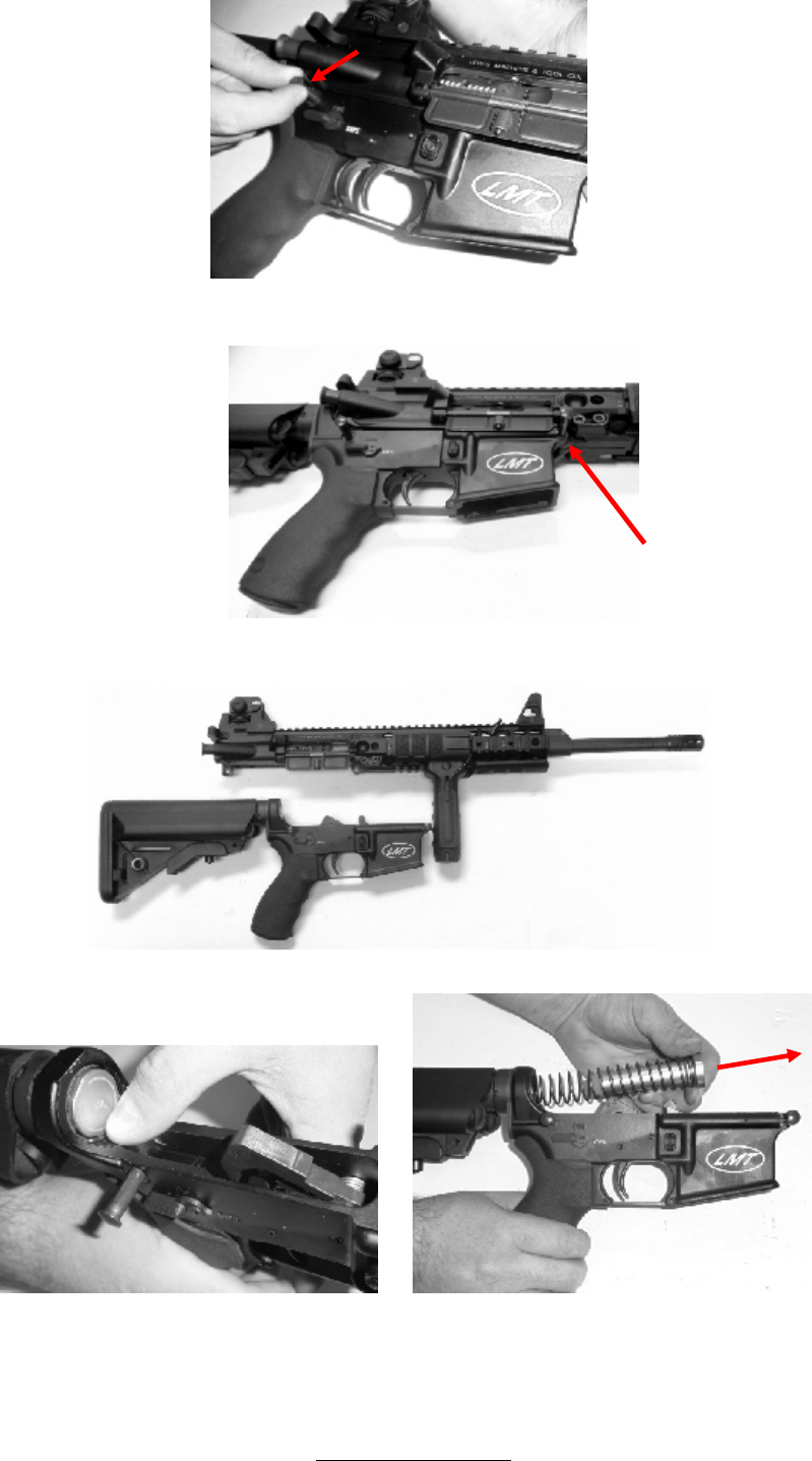
• Grasp the charging handle in an overhand grasp with the right hand, and pull it to the rear.
Rev F www.lmtdefense.com Page
23
• With the charging handle held to the rear, depress the bolt release catch with the thumb of the left
hand. Slowly allow the charging handle to return forward until the working parts contact the bolt
release catch. The bolt will now be retained by the bolt release catch, and the charging handle should
be pushed fully forward. Return the right hand to the pistol grip, and control the weapon with the left
hand on the hand-guard.
• Tilt the weapon over to the left. Look into the ejection opening port ensuring the front face of the bolt
and the chamber are clear from ammunition or obstructions. At night or in poor visibility, insert the little
finger of the right hand to ensure the chamber and front face of the bolt are clear.
• With the thumb of the left hand, depress the bolt release catch. The working parts will now move
forward under influence of their spring, and the bolt will close and lock.
Rev F www.lmtdefense.com Page
24
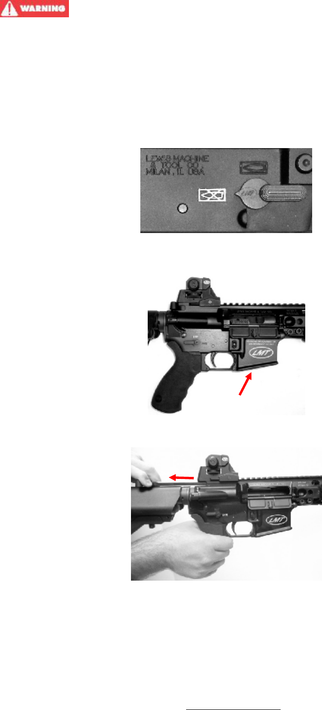
• From the left-hand side push the rear locking pin to the right. From the right-hand side, pull the rear
takedown pin until it comes to a positive stop.
• From the left-hand side push the rear locking pin to the right. From the right-hand side, pull the front
pivot pin until it comes to a positive stop.
•
• Separate the upper and lower receivers.
• With the hammer in cocked position, depress the buffer retainer. Remove the buffer and recoil spring.
• Rotate the selector lever to the “FIRE” position.
• With your free hand, hold the hammer, not allowing it to slam forward, and operate the trigger. This will
allow the hammer assembly to be released from the cocked position.
Rev F www.lmtdefense.com Page
25
NOTE: Standard carbines use the standard unmarked buffer.
All piston operated rifles use the H2 buffer. The LM308MWS
uses the H3 buffer.
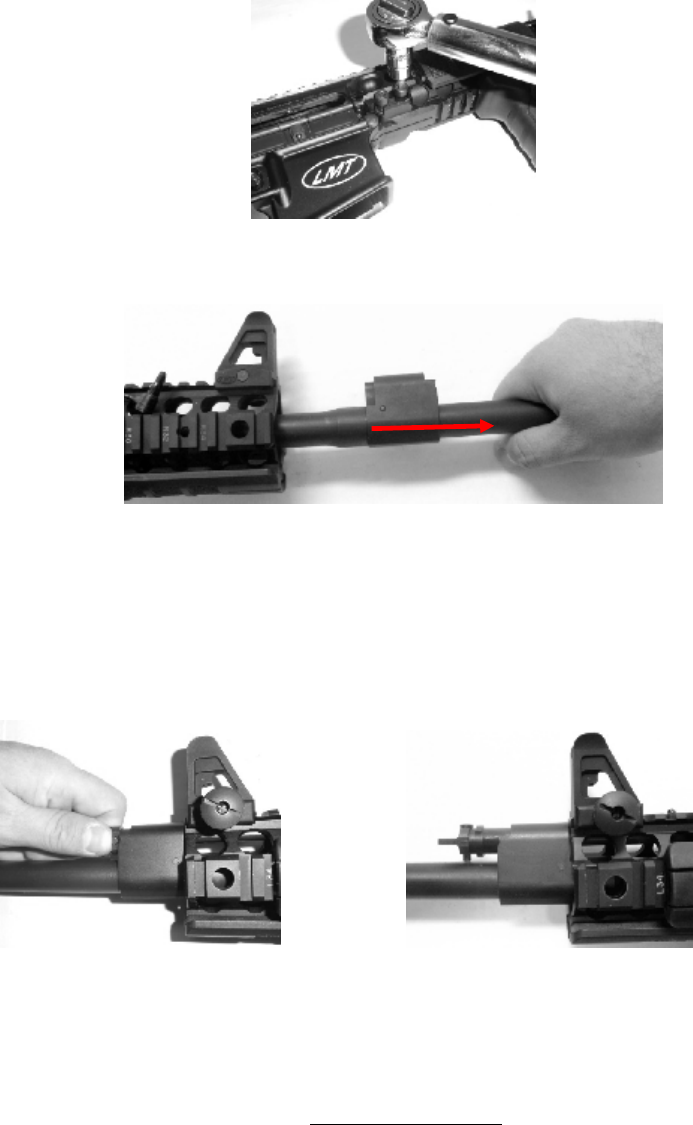
BARREL REMOVAL AND INSTALLATION (REFER TO FIGURE 5A)
• Removing Barrel from Upper Receiver
o NOTE: BARREL MUST BE COOL TO THE TOUCH BEFORE PROCEEDING WITH BARREL
REMOVAL AND INSTALLATION.
o If a carrier group exists, remove it from the upper receiver.
o Using a T-30 Torx wrench, remove the front bolt (1) from the receiver. Proceed to the rear
bolt (2) and loosen using three complete turns. ***Note, the screw does not need to be
removed.***
o Grasp the muzzle end of the barrel and pull the barrel from the receiver.
• Installing the MRP™ Weapon System Barrel into the Upper Receiver
o If a carrier group exists, remove it from the upper receiver. Slide the replacement barrel into
the upper receiver. Be sure that the gas tube is in the 12 o’clock position. After the barrel is
fully inserted into the receiver, install the front bolt (1) into the receiver. Using the pre-set
torque wrench which was supplied with the original purchase of the rifle, tighten the front bolt
(1) to 140 inch pounds. Proceed to the rear bolt (2) and follow the above instructions.
ASSEMBLY AND DISASSEMBLY PISTON SYSTEM
• To disassemble, depress the plunger while rotating the plug in the direction indicated (counter
clockwise from the direction of the breech) until the locking lug is in position to allow the removal of the
plug (approximately 90°).

Rev F www.lmtdefense.com Page
26
• Pull the plug/operating rod from the gas block. The piston should come with the plug due to the high-
quality fit.
• The piston is easy to remove from the plug with gentle hand pressure.
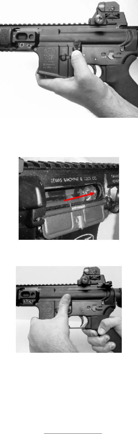
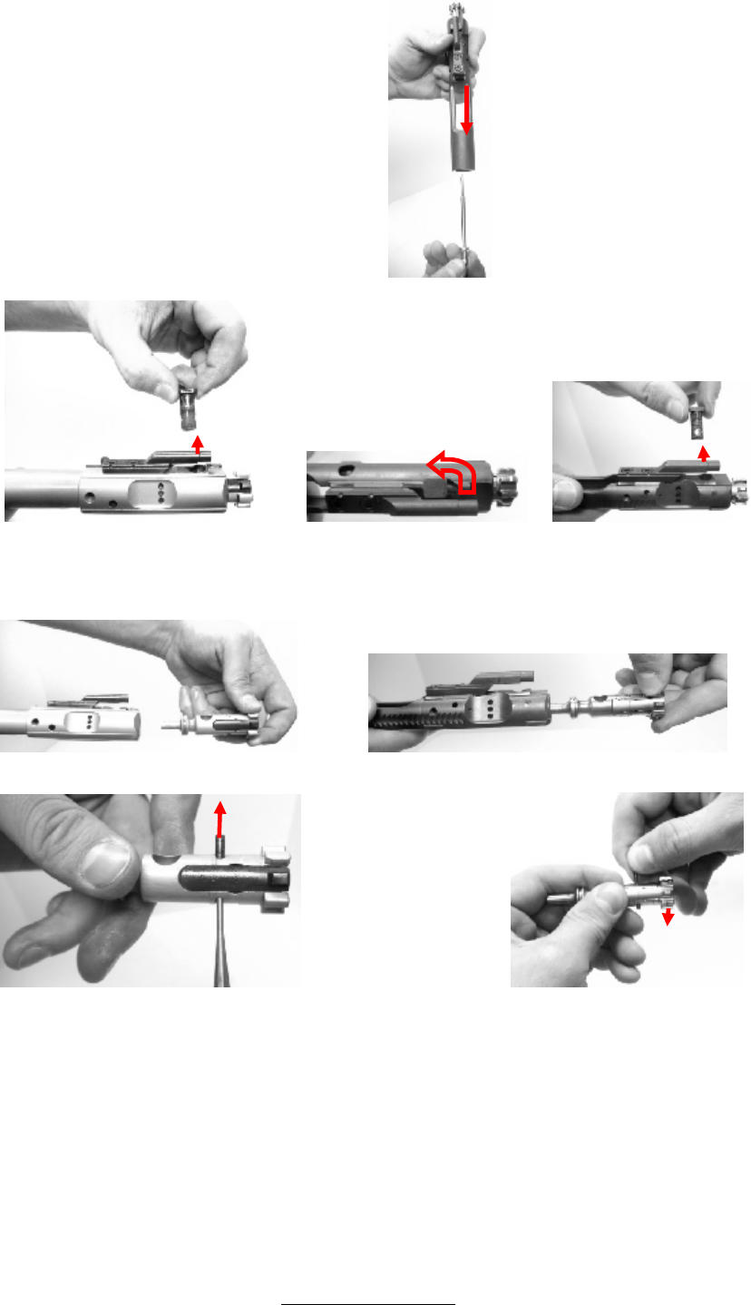
REMOVING THE BOLT AND CARRIER ASSEMBLY
• Pull the charging handle to the rear. Remove the bolt carrier assembly from the upper receiver.
• Pull the charging handle fully to the rear, and disengage it from the upper receiver by moving it
downwards so the expanded end of the charging handle passes through the cut-out in the guide way.
7.62x51/308 Win Carrier 5.56x45mm Carrier
• Cup the bolt and carrier assembly in one hand and with a suitable drift or point of cartridge. Push out
the firing pin retaining pin. Note the 7.62x51mm/308 Win firing pin retainer pin is captivated and should
not be removed from the carrier.
Captive Firing Pin
Retainer Pin
Removable Firing
Pin Retainer Pin
Rev F www.lmtdefense.com Page
27
• Slide the firing pin out of the rear of the bolt carrier.
7.62x51mm/308 Win 5.56x45mm 5.56x45mm
• On the 7.62x51mm/308 Win bolt carrier, rotate the bolt into the locked position and lift the cam pin out
of the carrier. On the 5.56mm direct gas and piston operated bolt carriers rotate the bolt to the locked
position. Rotate the cam pin ¼ of a turn and remove it from the bolt carrier
7.62x51mm/308 Win 5.56x45mm Enhanced bolt and carrier
• The bolt can now be Remove the bolt from the carrier.
• Holding the bolt in one hand you can push out the Extractor Pivot Pin slightly with the Firing Pin
Retainer Pin or a suitable tool. Once the Extractor Pivot Pin is partially out, you can remove it by
pulling it with your fingers and remove the Extractor.

Rev F www.lmtdefense.com Page
28
7.62x51mm/308 Win 5.56x45mm Enhanced 5.56x45mm Standard
• The Bolt and Extractor components are now ready for a detailed cleaning. Notice the Enhanced Bolt
has two extractor springs.
REASSEMBLY
• Reassembly is the reverse of stripping.
REPLACING BUFFER AND ACTION SPRING
• Ensure the hammer is in the cocked position. Place the return spring onto the buffer. Turn the spring
½ turn clockwise to ensure it is seated correctly.
• Replace the buffer and action spring into the butt of the lower receiver. Depress the buffer retaining
pin with a suitable drift and push the buffer into the butt. Release the buffer retaining pin and, while
maintaining control, allow the buffer to move forward under influence of its spring. Ensure the buffer
retaining pin has reasserted itself and retains the buffer.
REASSEMBLY OF UPPER AND LOWER RECEIVER
• Align the upper and lower receiver together in the open position. Ensure locking pin holes are aligned.
Push the forward front pivot pin from right to left.
REASSEMBLY OF BOLT AND CARRIER
• Replace the bolt into the carrier.
• NOTE: Ensure the cam pinhole with the two indentations is to the bottom. Align the cam pinhole in the
bolt with the rear of the cam recess in the carrier.
• Replace the cam pin. Rotate the cam pin to align its firing pin hole with the axis of the bolt.
IT IS ESSENTIAL THAT THE CAM PIN IS REPLACED AT THIS POINT. FAILURE TO
REPLACE THE CAM PIN MAY CAUSE A DANGEROUS SITUATION DURING FIRING CAUSING
PERSONAL INJURY OR DEATH.
• Insert the firing pin through the rear of the carrier and ensure it is fully seated. Pull the bolt fully
forward into the locked position. Replace the firing pin retaining pin from the left side of the carrier.
Verify that when the bolt is fully inserted into the Bolt Carrier, push on the back side of the firing pin to
verify that the pin is protruding out the bolt face.
REPLACING THE BOLT AND CARRIER ASSEMBLY
• Replace the charging handle by engaging the expanded end into the recess in the upper receiver
guide way. Partially push the charging handle forward.
• Ensure the bolt is in the unlocked position in the carrier. Align the carrier key to the recess in the
underside of the charging handle. Slide the carrier assembly into the upper receiver. Push the carrier
assembly and the charging handle forward until a distinctive click is heard, then they are fully located
into the upper receiver.
• In the lower assembly, push the hammer back into the cocked position. Once this is done, make
sure the selector lever in the “Safe” position.
• Join the upper and lower receiver together. Push the rear takedown pin into the lower receiver from
the right hand side.

Rev F www.lmtdefense.com Page
29
REPLACING ACCESSORIES
• Replace the sights, sling and any other accessories if applicable.
INSTALLATION AND REMOVAL OF SOPMOD BUTTSTOCK
• Removing Buttstock from Extension Tube
• Grasp the release lever (Figure 12 (5)) on the checkered end. While pulling the release lever away
from the buttstock, slide the buttstock (Figure 12 (3)) off the end of the extension tube (Figure 2 (2)).
• Removing Battery Tubes from Buttstock
o After removing the buttstock from the extension tube, grasp the battery tube cap (Figure 12 (8))
and turn towards the opening. When the cap (Figure 12 (10)) clears the opening, pull the battery
tube (Figure 12 (8)) from the buttstock. ***Note, the flat sides that run the length of the battery
tubes are positioned towards the center of the buttstock against the flat in the tube compartment.
Ensure while replacing the tubes that the caps are fully rotated into the slot and the flats are
against their mating flat surface.
• Removing End Plate from Buttstock
o Grasp both tabs simultaneously on the end plate (Figure 12 (4)). Apply inward force to both tabs
while pulling the end plate away from the buttstock.

Rev F www.lmtdefense.com Page
30
FUNCTIONING
After stripping and reassembly of the weapon, the user must always carry out the function test to ensure that
all operations will function properly. Tilt the weapon over to the left. Look into the ejection opening port
ensuring the front face of the bolt and the chamber are clear from ammunition or obstructions.
Cock the weapon, rotate the fire selector lever to “Safe” and attempt to fire off the action. It must not fire.
Rotate the fire selector lever to “Fire”.
Rotate the fire selector lever to “Auto”.
• Operate the trigger but do not release the trigger. The hammer should rotate forward about its axis
under influence of its spring.
• Ensure the trigger is not released. Cock the weapon. The hammer should be retained to the rear by
the disconnector. Release the trigger. The hammer should be heard / felt to disengage from the
disconnector to be immediately retained by the sear.

Rev F www.lmtdefense.com Page
31
ONE YEAR LIMITED WARRANTY
Lewis Machine and Tool Co. warrants to the initial retail purchaser that LMT™ firearm will be free of defects in
workmanship and material for a period of one year from the date of purchase. Any such defects of which Lewis
Machine and Tool Co. is given written notice within one year and ten days from the date of the initial retail
purchase by the initial retail purchaser will be remedied by Lewis Machine and Tool Co. as provided below.
Upon receiving timely notice from the initial retail purchaser and complying with instructions for return of the
firearm, Lewis Machine and Tool Co. shall have the option of repairing or replacing any part claimed or found
to be defective. Correction of the claimed condition in this manner shall constitute fulfilment of all obligations of
Lewis Machine and Tool Co. under this ONE YEAR LIMITED WARRANTY. Products deemed by Lewis
Machine and Tool Co. to be unsafe shall not be returned. This ONE YEAR LIMITED WARRANTY does not
cover any condition determined by Lewis Machine and Tool Co. to be caused by or arising out of unauthorized
repairs or modifications, negligent or careless use, normal wear and tear, abuse, failure to properly store or
maintain the product, disassembly beyond the FIELD STRIPPING instructions in this manual, use of defective
or improper ammunition, corrosion, or neglect. This ONE YEAR LIMITED WARRANTY is exclusive and is in
lieu of all or any other warranties written or oral, express or implied.
To initiate a warranty claim call Lewis Machine and Tool Co. Customer Service ((309) 732.9527 Monday
through Friday 8 AM to 3 PM CDT) within the LIMITED WARRANTY period to get a Return Goods
Authorization number (RGA). Then ship the firearm prepaid along with a written description of the difficulty and
proof of purchase to Lewis Machine and Tool Co., Customer Service Dept,. 1305-11
th
St. West, Milan, Il
61264
LEWIS MACHINE AND TOOL CO. MAKES NO WARRANTY OF MERCHANTABILITY OR
FITNESS FOR PARTICULAR PURPOSE, AND LEWIS MACHINE AND TOOL CO. SHALL
HAVE NO LIABILITY FOR INCIDENTAL OR CONSEQUENTIAL DAMAGES.
DISCLAIMER OF LIABILITY
Lewis Machine and Tool Co. disclaims any liability for personal injury, property damage or economic loss
caused in whole or in part by handloaded, reloaded, remanufactured or defective ammunition. Under no
circumstances will Lewis Machine and Tool Co. be liable for personal injury, property damage or economic
loss resulting from unsafe handling or the firearm, or unauthorized modifications to the firearm.
THE ABOVE LIMITED ONE YEAR WARRANTY AND DISCLAIMER OF LIABILITY IS
SUBJECT TO ALL APPLICABLE LAWS, SOME OF WHICH MAY LIMIT ITS TERMS.

Rev F www.lmtdefense.com Page
32
WEAPON – GENERAL SPECIFICATION
TABLE 1
LMT™ MODULAR WEAPON SYSTEM CHARACTERISTICS
MECHANICAL FEATURES
Characteristic LM308MWS CQB (5.56MM) CQB (6.8MM)
SYSTEM OF OPERATION GAS AND MAGAZINE FED
GAS AND
MAGAZINE FED
GAS AND
MAGAZINE FED
METHOD OF LOCKING
ROTATING
BOLT
ROTATING
BOLT
ROTATING
BOLT
NUMBER OF GROOVES
SS = 5 RIGHT HAND
CR-MO-V = 5 RIGHT HAND
6 RIGHT HAND 6 RIGHT HAND
PITCH OF RIFLING - 1 TURN IN
SS = 286MM / 11.25 IN
CR-MO-V = 254MM / 10.0 IN
177.8 MM
7.0 IN
254 MM
10.0 IN
OVERALL LENGTH
BUTTSTOCK COLLAPSED 886 MM / 34.88 IN
835 MM
32.88 IN
835 MM
32.88 IN
BUTTSTOCK EXTENDED 965 MM / 38.00 IN
917.5 MM
36.13 IN
917.5 MM
36.13 IN
WEIGHTS
WEAPON - LESS
ACCESSORIES
4.5 kg / 9.98 lbs 3.3 kg / 7.2 lbs 3.3 kg / 7.2 lbs
AMMUNITION
CALIBER
.204 Ruger, .223, 5.56 NATO, .243, .260, 6.8 SPC, 6.5 Creedmoor
7MM-08, .300BLK, .308 Win, 7.62 NATO and .338 Federal
NATURES BALL / TRACER / BLANK / DRILL
SIGHTING SYSTEMS
PRIMARY SIGHT DETACHABLE IRON SIGHT SYSTEM (DISS)
FRONT SIGHT ADJUSTABLE BLADE
REAR SIGHT ADJUSTABLE DUAL LEAF APERTURE
The rifle comprises five main assemblies: upper receiver assembly, barrel assembly, lower receiver, bolt
carrier group and tactical sight units.
UPPER RECEIVER ASSEMBLY (REFER TO FIGURE 5)
The Upper Assembly provides a means of imparting direction and stability to the round along with consistency
of the sighting and accessory system provided by the user. It also houses the gas tube which aids in the cycle
of the weapon. The Upper Assembly consists of an MRP™ Weapon System (Figure 5 (1)) and Barrel
Assembly (Figure 5 (2)).

Rev F www.lmtdefense.com Page
33
BARREL ASSEMBLY (REFER TO FIGURE 7)
The Barrel Assembly along with the Bolt Carrier Group and Magazine can be changed by the operator / user
to accommodate various calibers.
There are configuration and operational differences between the standard gas tube system and the piston
system.
STANDARD (DIRECT IMPINGEMENT) GAS TUBE SYSTEM (REFER TO FIGURE 7A)
• The barrel (Figure 7A (2)) is threaded at the front to receive the compensator (Figure 7A (3)) and held in
place with a crush washer (Figure 7A (4)). Various compensators are available to match the operator’s
needs. The barrel has a drilled hole which allows gas to be vented through the gas block into the gas tube
(Figure 7A (1)) which is held in place with a roll pin (Figure 7A (5)).
• The gas tube (Figure 7A (1)) is retained by the gas tube pin; and the barrel assembly is retained in the
rear by the upper receiver.
PISTON SYSTEM (REFER TO FIGURE 7B)
• The barrel (Figure 7B (1)) is threaded at the front to receive the compensator (Figure 7B (6)) and held in
place with a crush washer (Figure 7B (7)). Various compensators are available to match the operator’s
needs. The barrel has a piston plug and rod assembly that facilitates the weapons action.
• When the rifle is fired, the developing gases expand inside of the gas block much like a traditional
Standard Gas System (DI). The expanding gases push against the short stroke piston (Figure 7B (5))
which exerts pressure on the operating rod (Figure 7B (3))and thus gives momentum to the bolt carrier.
Once the piston (Figure 7B (4)) itself has travelled less than 1.0 Inch (25MM), it expels any unused gases
from a small vent in the bottom of the piston tube. Once the cycle of the action is in progress, the piston
moves to the back of its chamber awaiting the return of the operating rod to push it back into its normal
resting state.
• The barrel assembly (Figure 7B) is retained in the rear by the upper receiver.
LOWER RECEIVER ASSEMBLY (REFER TO FIGURE 2)
The Lower Assembly provides a means of controlling the fire and safety mechanism. This mechanism consists
of the trigger, hammer (Figure 4), and selector lever (Figure 3). The lower receiver (Figure 2 (25)) also houses
the magazine well and catch (Figure 2 (23)) which allows the operation to hold a multi round magazine (Figure
1 (9)) that is provided. It also houses the buffer (Figure 2 (9)) and spring system (Figure 2 (3)) aids in the cycle
of the weapon.
BOLT CARRIER GROUP (REFER TO FIGURE 9)
The Bolt Carrier Group consists of the Bolt Carrier (Figure 10), Bolt (Figure 11) and Firing Pin (Figure 9 (2)).
This assembly is what operates with the gas system to help in the ejection of the spent cartridge and loads the
next cartridge for firing from the magazine. When the trigger (Figure 4 (6)) is squeezed, it rotates rearward
about its axis, disengaging the sear from the hammer. The hammer then rotates forward under influence of its
own spring (Figure 4 (5)). The front face of the hammer strikes the rear face of the firing pin (Figure 9 (2)),
driving it forward impacting against the rear of the primer in the round. This ignites the propellant in the round,
driving the projectile through the barrel.
The Bolt Carrier Group along with the Barrel Assembly and Magazine can be changed by the operator / user
to accommodate various calibers.
TACTICAL SIGHT UNITS (REFER TO FIGURE 1)
The tactical sight unit comprises of two units, Front Tactical Sight (Figure 1 (1)) and the Rear Tactical Sight
Unit (Figure 1 (2)). The front site post is moved up or down when zeroing the rear sight. Adjustments can be
made by depressing the locking pin with a bullet tip and twisting the post or a special adjustment tool (NSN
9510-00-640-4407). The Tactical Rear Sight has a dual aperture for normal and longer range firing. Windage
adjustments can be made with rear sight.
Rev F www.lmtdefense.com Page
34
You can now access spare parts, replacement parts and accessories by going to www.lmtdefense.com. If
you prefer to speak to a customer service representative, or do not see the item listed please contact us at
309.732.9527.
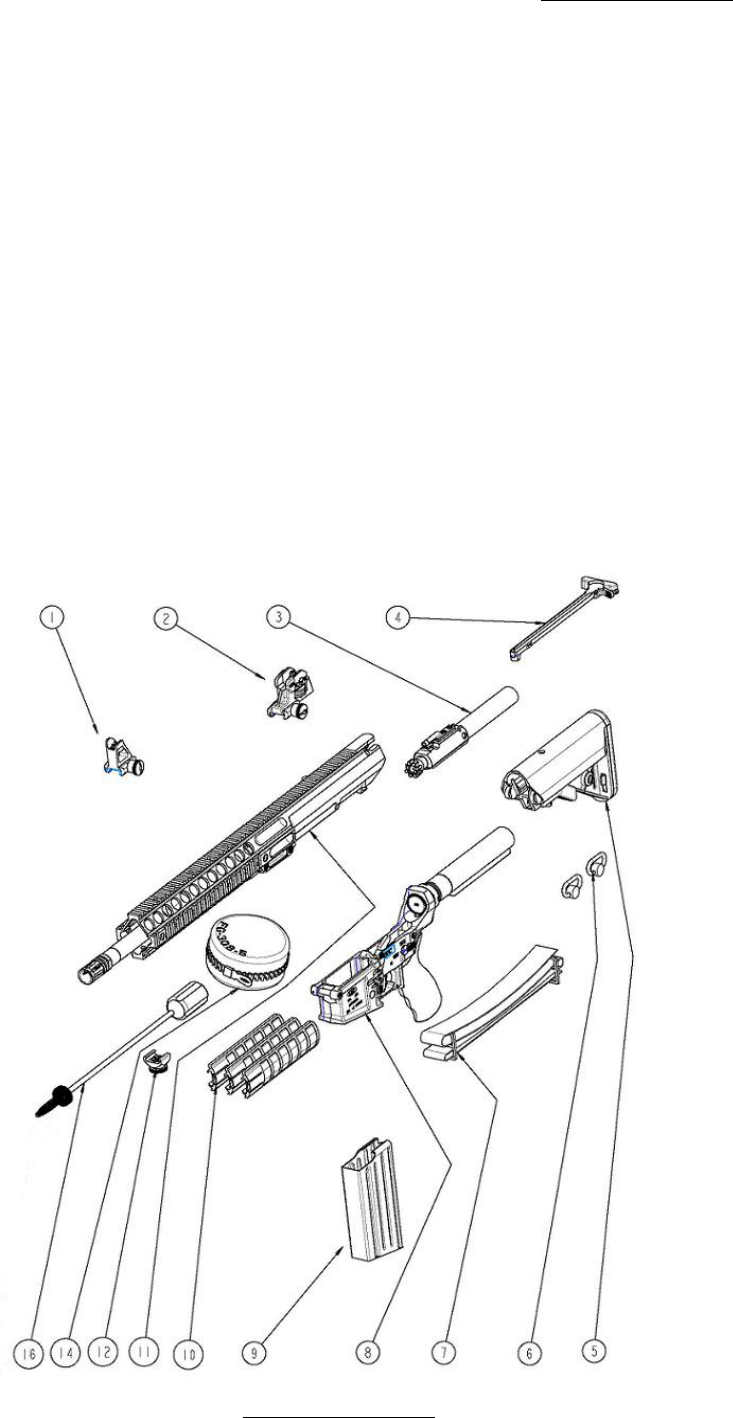
RIFLE ASSEMBLY (FIGURE 1)
ITEM
DESCRIPTION
QUANTITY
1 TACTICAL FRONT SIGHT 1.0000 ea
2 TACTICAL REAR SIGHT 1.0000 ea
3 CARRIER GROUP ASSEMBLY 1.0000 ea
4 CHARGING HANDLE ASSEMBLY 1.0000 ea
5 SOPMOD BUTTSTOCK ASSEMBLY 1.0000 ea
6 SLING MOUNT** 2.0000 ea
7 STANDARD SLING 1.0000 ea
8 ASSEMBLY, LOWER 1.0000 ea
9 MAGAZINE 1.0000 ea
10 RAIL PANEL FULL PANEL 3.0000 ea
11 ASSEMBLY, UPPER RECEIVER 1.0000 ea
12 SLIDING SLING MOUNT** 1.0000 ea
13 OPERATORS MANUAL 1.0000 ea
14 CLEANING KIT** 1.0000 ea
15 RIFLE CASE** 1.0000 ea
16 CLEANING ROD** 1.0000 ea
** Optional Equipment

Rev F www.lmtdefense.com Page
35
You can now access spare parts, replacement parts and accessories by going to www.lmtdefense.com. If
you prefer to speak to a customer service representative, or do not see the item listed please contact us at
309.732.9527.
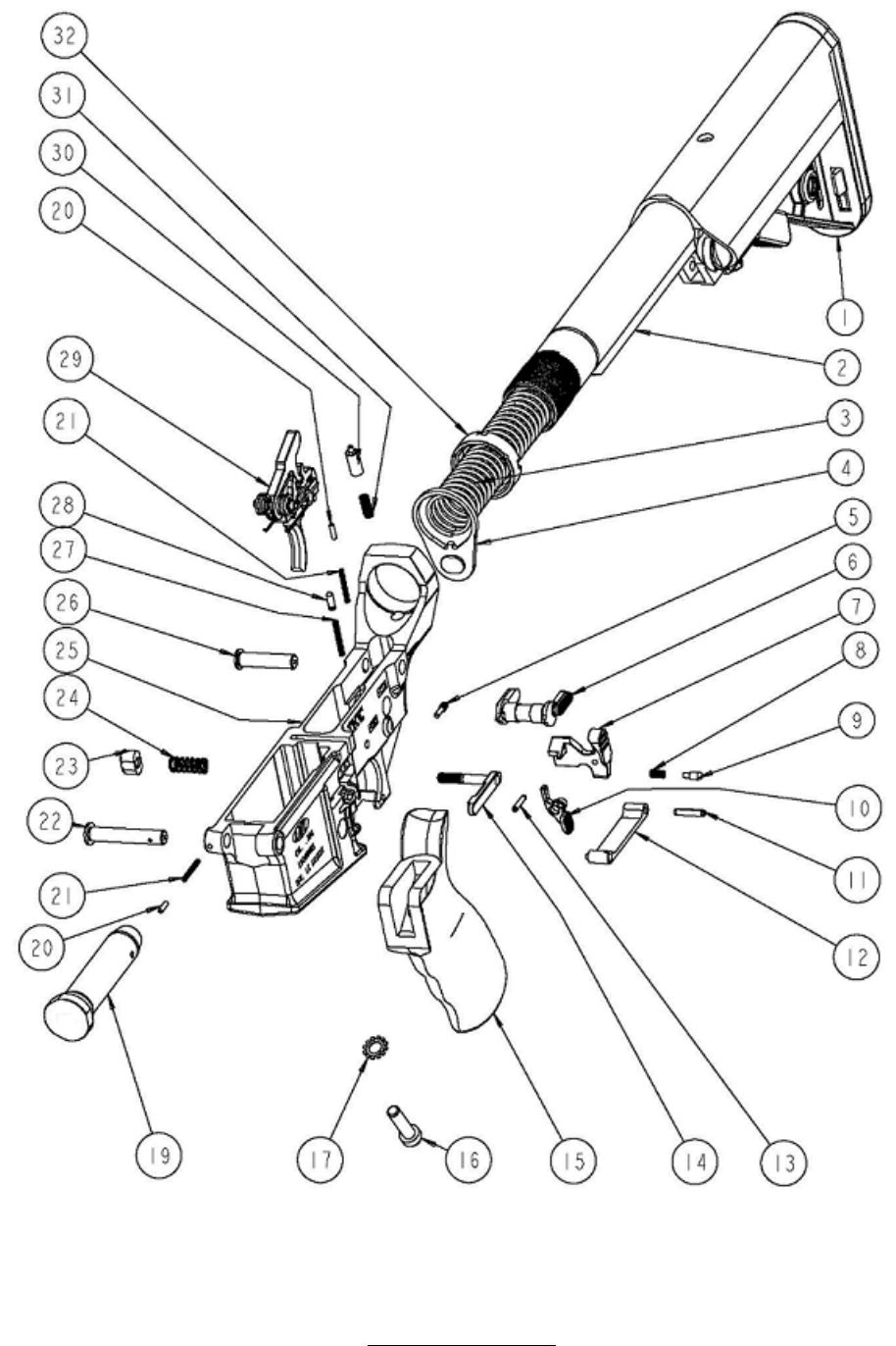
LOWER ASSEMBLY – SEMI AUTOMATIC (FIGURE 2A)
ITEM
DESCRIPTION
Quantity
1 BUTTSTOCK SOPMOD 1.0000 ea
2 TUBE, RECEIVER EXTENSION 1.0000 ea
3 SPRING, ACTION 1.0000 ea
4 SLING LOOP REC. END PLATE 1.0000 ea
5 RETAINING PIN, BOLT CATCH 1.0000 ea
6 SELECTOR AMBI SEMI AUTO ASSEMBLY 1.0000 ea
7 CATCH, BOLT 1.0000 ea
8 SPRING, BOLT CATCH 1.0000 ea
9 PLUNGER, BOLT CATCH 1.0000 ea
10 AMBI MAG RELEASE 1.0000 ea
11 PIN, ROLL, TRIGGER GUARD 1.0000 ea
12 ASSEMBLY, TRIGGER GUARD 1.0000 ea
13 PIN, SPRING SLOTTED 1.0000 ea
14 CATCH, MAGAZINE 1.0000 ea
15 LMT™ GRIP 1.0000 ea
16 SCREW, PISTOL GRIP 1.0000 ea
17 LOCK WASHER 1.0000 ea
19 BUFFER ASSEMBLY 1.0000 ea
20 DETENT, TAKEDOWN 2.0000 ea
21 SPRING, DETENT, TAKEDOWN 2.0000 ea
22 PIN, RECEIVER PIVOT 1.0000 ea
23 BUTTON, MAGAZINE CATCH 1.0000 ea
24 SPRING, MAGAZINE CATCH 1.0000 ea
25 RECEIVER, LOWER 1.0000 ea
26 PIN, TAKEDOWN 1.0000 ea
27 SPRING, SAFETY DETENT 1.0000 ea
28 DETENT, FIRE CONTROL 1.0000 ea
29 2 STAGE TRIGGER ASSEMBLY 1.0000 ea
30 RETAINER, BUFFER 1.0000 ea
31 SPRING, BUFFER RETAINER 1.0000 ea
32 NUT, RECEIVER EXTENSION 1.0000 ea
(For illustration, see next page)

Rev F www.lmtdefense.com Page
37
You can now access spare parts, replacement parts and accessories by going to www.lmtdefense.com. If
you prefer to speak to a customer service representative, or do not see the item listed please contact us at
309.732.9527.
LOWER ASSEMBLY – FULL AUTOMATIC (FIGURE 2B)
ITEM
DESCRIPTION
Quantity
1 BUTTSTOCK SOPMOD 1.0000 ea
2 TUBE, RECEIVER EXTENSION 1.0000 ea
3 SPRING, ACTION 1.0000 ea
4 SLING LOOP REC. END PLATE 1.0000 ea
5 RETAINING PIN, BOLT CATCH 1.0000 ea
6 SELECTOR AMBI FULL AUTO ASSEMBLY 1.0000 ea
7 CATCH, BOLT 1.0000 ea
8 SPRING, BOLT CATCH 1.0000 ea
9 PLUNGER, BOLT CATCH 1.0000 ea
10 AMBI MAG RELEASE 1.0000 ea
11 PIN, ROLL, TRIGGER GUARD 1.0000 ea
12 ASSEMBLY, TRIGGER GUARD 1.0000 ea
13 PIN, SPRING SLOTTED 1.0000 ea
14 CATCH, MAGAZINE 1.0000 ea
15 LMT™ GRIP 1.0000 ea
16 SCREW, PISTOL GRIP 1.0000 ea
17 LOCK WASHER 1.0000 ea
19 BUFFER ASSEMBLY 1.0000 ea
20 DETENT, TAKEDOWN 2.0000 ea
21 SPRING, DETENT, TAKEDOWN 2.0000 ea
22 PIN, RECEIVER PIVOT 1.0000 ea
23 BUTTON, MAGAZINE CATCH 1.0000 ea
24 SPRING, MAGAZINE CATCH 1.0000 ea
25 RECEIVER, LOWER 1.0000 ea
26 PIN, TAKEDOWN 1.0000 ea
27 SPRING, SAFETY DETENT 1.0000 ea
28 DETENT, FIRE CONTROL 1.0000 ea
29 FULL AUTO TRIGGER ASSEMBLY 1.0000 ea
30 RETAINER, BUFFER 1.0000 ea
31 SPRING, BUFFER RETAINER 1.0000 ea
32 NUT, RECEIVER EXTENSION 1.0000 ea
(For illustration, see next page)

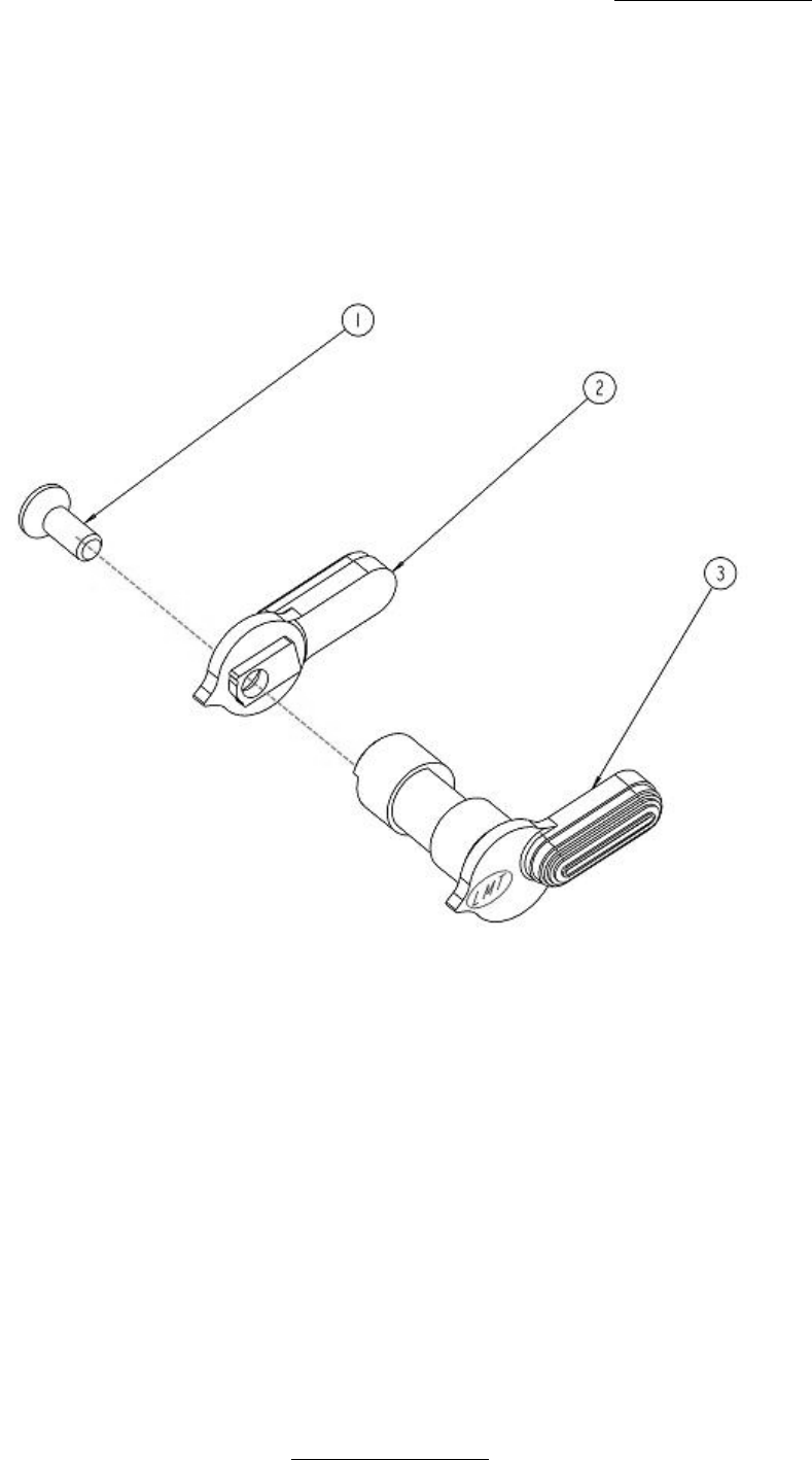
Rev F www.lmtdefense.com Page
39
You can now access spare parts, replacement parts and accessories by going to www.lmtdefense.com. If
you prefer to speak to a customer service representative, or do not see the item listed please contact us at
309.732.9527.
SELECTOR AMBI SEMI / FULL AUTO ASSEMBLY (FIGURE 3)
ITEM
DESCRIPTION QUANTITY
1 6-32 FLATHEAD SCREW 1.0000 ea
2 LEFTY, FIRE SWITCH 1.0000 ea
3 SELECTOR AMBI SEMI 1.0000 ea
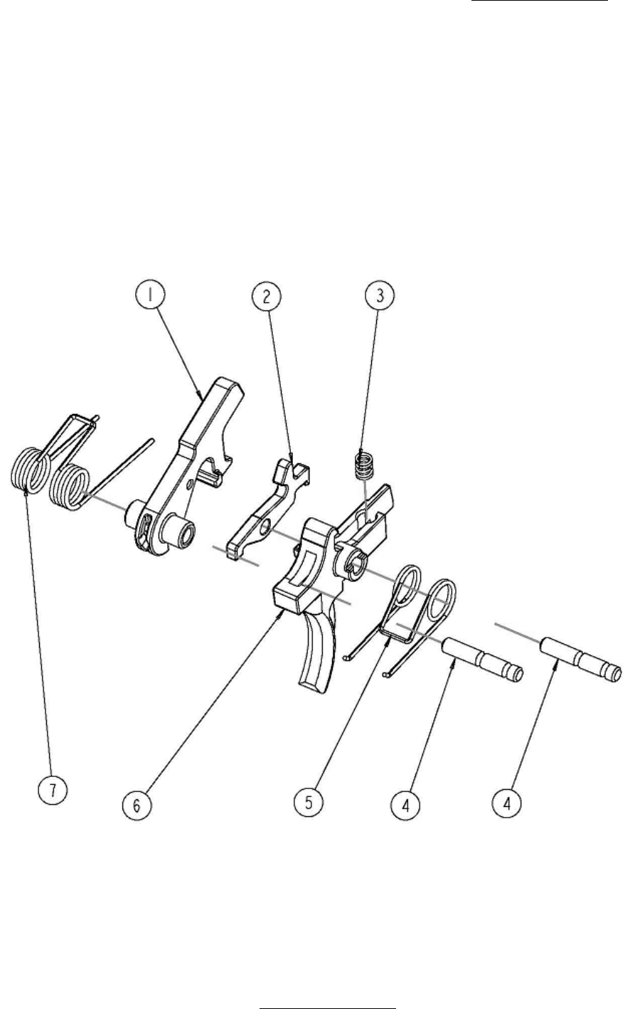
Rev F www.lmtdefense.com Page
40
You can now access spare parts, replacement parts and accessories by going to www.lmtdefense.com. If
you prefer to speak to a customer service representative, or do not see the item listed please contact us at
309.732.9527.
2 STAGE TRIGGER ASSEMBLY (FIGURE 4A)
ITEM
DESCRIPTION QUANTITY
1 HAMMER ASSEMBLY 1.0000 ea
2 DISCONNECTOR 1.0000 ea
3 SPRING 1.0000 ea
4 HAMMER-TRIGGER PIN 2.0000 ea
5 SPRING, TRIGGER 1.0000 ea
6 TRIGGER 1.0000 ea
7 SPRING, HAMMER 1.0000 ea
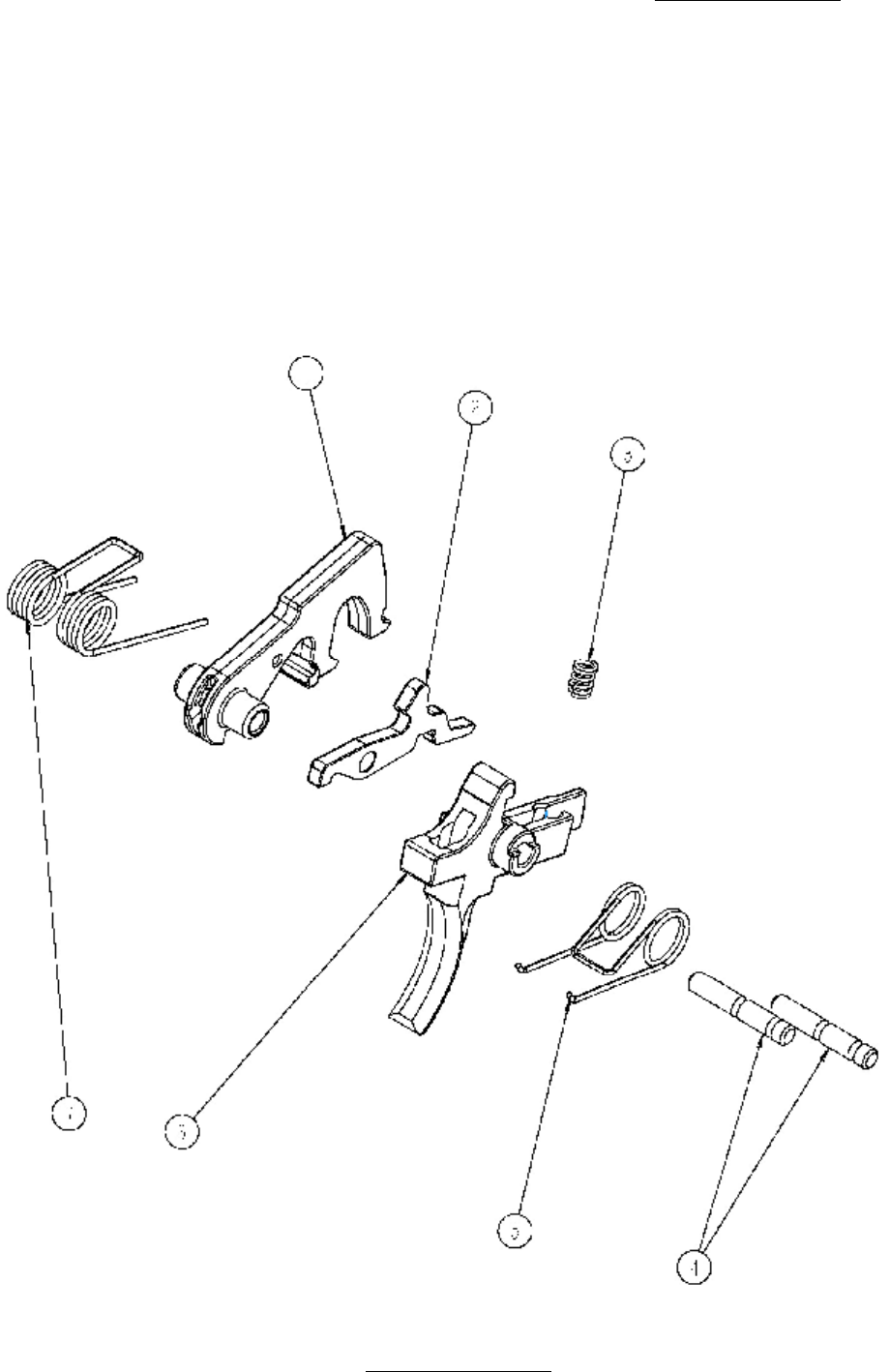
Rev F www.lmtdefense.com Page
41
You can now access spare parts, replacement parts and accessories by going to www.lmtdefense.com. If
you prefer to speak to a customer service representative, or do not see the item listed please contact us at
309.732.9527.
FULL AUTOMATIC TRIGGER ASSEMBLY (FIGURE 4B)
ITEM
DESCRIPTION QUANTITY
1 HAMMER ASSEMBLY 1.0000 ea
2 DISCONNECTOR 1.0000 ea
3 SPRING 1.0000 ea
4 HAMMER-TRIGGER PIN 2.0000 ea
5 SPRING, TRIGGER 1.0000 ea
6 TRIGGER 1.0000 ea
7 SPRING, HAMMER 1.0000 ea

Rev F www.lmtdefense.com Page
42
You can now access spare parts, replacement parts and accessories by going to www.lmtdefense.com. If
you prefer to speak to a customer service representative, or do not see the item listed please contact us at
309.732.9527.
UPPER ASSEMBLY (FIGURE 5)
ITEM
DESCRIPTION QUANTITY
1 ASSEMBLY, UPPER RECEIVER 1.0000 ea
2 BARREL ASSEMBLY 1.0000 ea
FIGURE 5A

Rev F www.lmtdefense.com Page
43
You can now access spare parts, replacement parts and accessories by going to www.lmtdefense.com. If
you prefer to speak to a customer service representative, or do not see the item listed please contact us at
309.732.9527.
UPPER RECEIVER ASSEMBLY (FIGURE 6)
ITEM
DESCRIPTION Quantity
1 WASHER, FLAT SS 1.0000 ea
2 SCREW, LOCKING 2.0000 ea
3 PIN, ROLL, BOLT CATCH 2.0000 ea
4 RING, RETAINING, EJECTION 1.0000 ea
5 PIN, EJECTION PORT COVER 1.0000 ea
6 EJECTION PORT COVER 1.0000 ea
7 SPRING, EJECTION PORT 1.0000 ea
8 RECEIVER, UPPER 1.0000 ea

Rev F www.lmtdefense.com Page
44
You can now access spare parts, replacement parts and accessories by going to www.lmtdefense.com. If
you prefer to speak to a customer service representative, or do not see the item listed please contact us at
309.732.9527.
BARREL ASSEMBLY – GAS/DI (FIGURE 7A)
ITEM
DESCRIPTION Quantity
1 ASSEMBLY, GAS TUBE 1.0000 ea
2 BARREL SUB ASSEMBLY 1.0000 ea
3 THREAD COMPENSATOR 1.0000 ea
4 SHIM WASHERS 1.0000 ea
5 PIN, ROLL, GAS TUBE 1.0000 ea
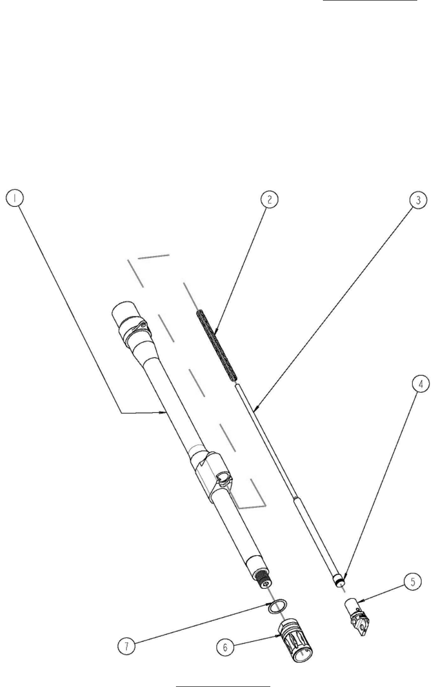
Rev F www.lmtdefense.com Page
45
You can now access spare parts, replacement parts and accessories by going to www.lmtdefense.com. If
you prefer to speak to a customer service representative, or do not see the item listed please contact us at
309.732.9527.
BARREL ASSEMBLY - PISTON (FIGURE 7B)
ITEM
DESCRIPTION Quantity
1 BARREL SUB ASSEMBLY 1.0000 ea
2 SPRING, COMPRESSION 1.0000 ea
3 PISTON, GAS 1.0000 ea
4 RING, PISTON 1.0000 ea
5 PLUG, GAS PISTON 1.0000 ea
6 THREAD COMPENSATOR 1.0000 ea
7 SHIM WASHERS 1.0000 ea
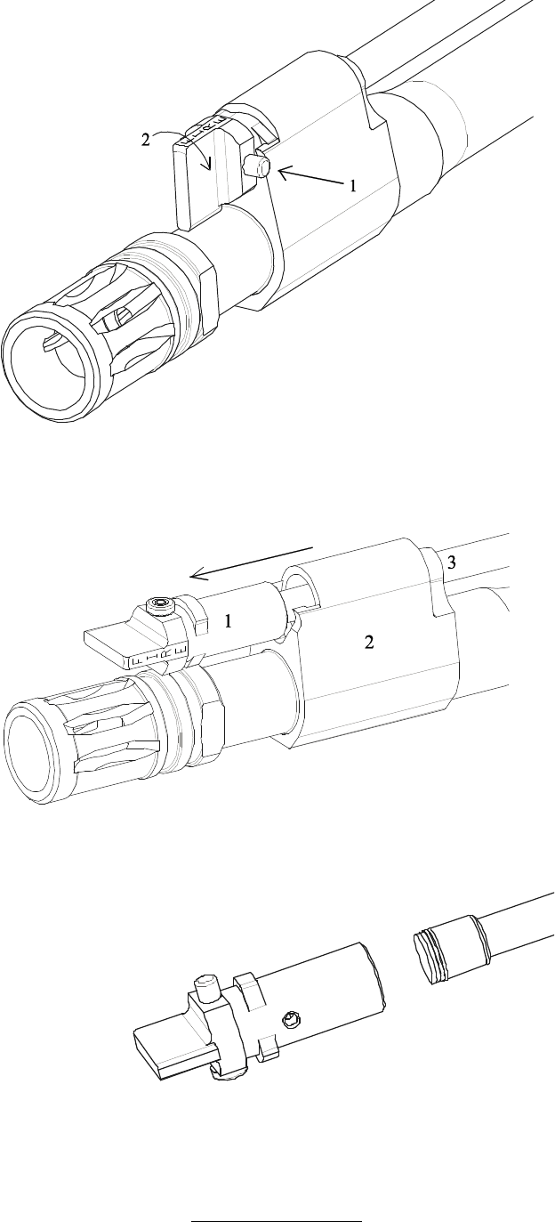

Rev F www.lmtdefense.com Page
47
You can now access spare parts, replacement parts and accessories by going to www.lmtdefense.com. If
you prefer to speak to a customer service representative, or do not see the item listed please contact us at
309.732.9527.
CHARGING HANDLE ASSEMBLY (FIGURE 8)
ITEM
DESCRIPTION QUANTITY
1 PIN, CHARGING HANDLE 1.0000 ea
2 SPRING, CHARGING HANDLE 1.0000 ea
3 TACTICAL CHARGING HANDLE LATCH 1.0000 ea
4 HANDLE, CHARGING 1.0000 ea
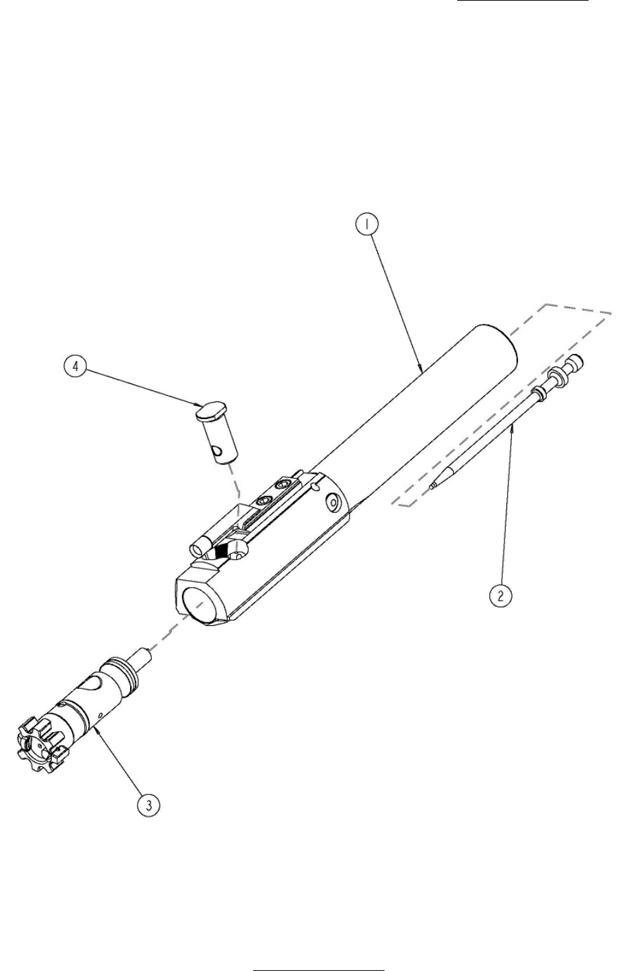
Rev F www.lmtdefense.com Page
48
You can now access spare parts, replacement parts and accessories by going to www.lmtdefense.com. If
you prefer to speak to a customer service representative, or do not see the item listed please contact us at
309.732.9527.
CARRIER GROUP ASSEMBLY – GAS/DI (FIGURE 9A)
ITEM
DESCRIPTION QUANTITY
1 CARRIER ASSEMBLY 1.0000 ea
2 FIRE PIN 1.0000 ea
3 BOLT ASSEMBLY 1.0000 ea
4 CAM PIN 1.0000 ea
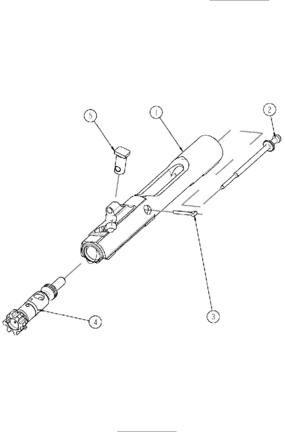
Rev F www.lmtdefense.com Page
49
You can now access spare parts, replacement parts and accessories by going to www.lmtdefense.com. If
you prefer to speak to a customer service representative, or do not see the item listed please contact us at
309.732.9527.
CARRIER GROUP ASSEMBLY - PISTON (FIGURE 9B)
ITEM
DESCRIPTION QUANTITY
1 CARRIER 1.0000 ea
2 FIRING PIN 1.0000 ea
3 PIN, RETAINING, FIRING 1.0000 ea
4 BOLT ASSEMBLY 1.0000 ea
5 CAM PIN 1.0000 ea

Rev F www.lmtdefense.com Page
50
You can now access spare parts, replacement parts and accessories by going to www.lmtdefense.com. If
you prefer to speak to a customer service representative, or do not see the item listed please contact us at
309.732.9527.
CARRIER ASSEMBLY (FIGURE 10)
ITEM
DESCRIPTION QUANTITY
1 KEY, GAS 1.0000 ea
2 SCREW, SOCKET HEAD CAP 2.0000 ea
3 PIN, SPRING SLOTTED 1.0000 ea
4 CARRIER, BOLT 1.0000 ea
5 RETAINING PIN, FIRE PIN 1.0000 ea

Rev F www.lmtdefense.com Page
51
You can now access spare parts, replacement parts and accessories by going to www.lmtdefense.com. If
you prefer to speak to a customer service representative, or do not see the item listed please contact us at
309.732.9527.
BOLT ASSEMBLY (FIGURE 11)
ITEM
DESCRIPTION QUANTITY
1 BOLT 1.0000 ea
2 EXTRACTOR 1.0000 ea
3 SPRING 1.0000 ea
4 BUFFER 1.0000 ea
5 SPRING EJECTOR 1.0000 ea
6 EJECTOR 1.0000 ea
7 EJECTOR, RETAINING PIN 1.0000 ea
8 EXTRACTOR PIVOT PIN 1.0000 ea
9 GAS RING ASSEMBLY 1.0000 ea
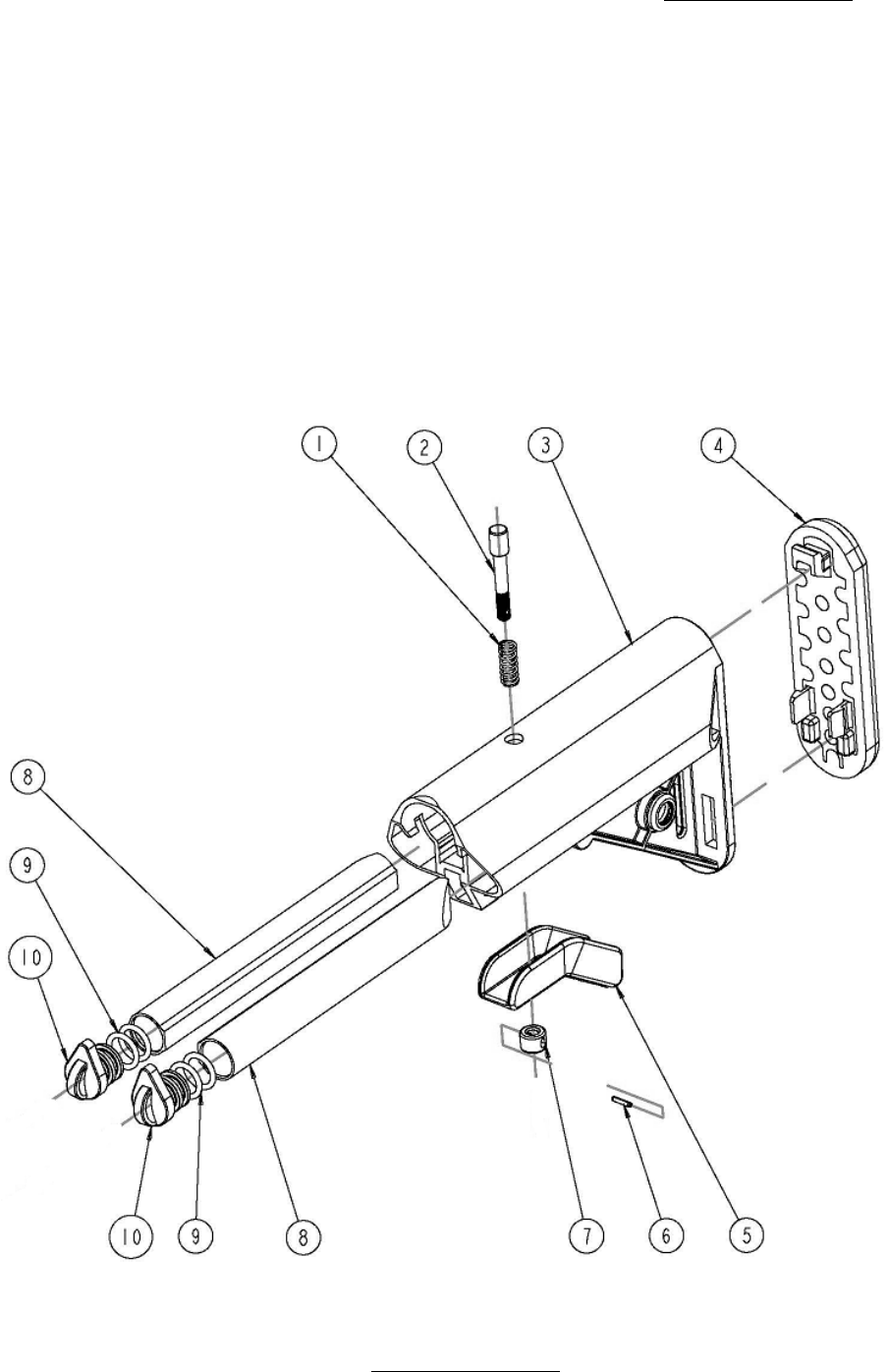
Rev F www.lmtdefense.com Page
52
You can now access spare parts, replacement parts and accessories by going to www.lmtdefense.com. If
you prefer to speak to a customer service representative, or do not see the item listed please contact us at
309.732.9527.
BUTTSTOCK ASSEMBLY (FIGURE 12)
ITEM DESCRIPTION QUANTITY
1 SPRING 1.0000 ea
2 PIN, LOCK 1.0000 ea
3 SOPMOD ASSEMBLY W/LRG HOLE 1.0000 ea
4 BUTTPLATE 1.0000 ea
5 LEVER, RELEASE 1.0000 ea
6 PIN, SPRING 1.0000 ea
7 NUT, LOCK PIN 1.0000 ea
8 TUBE 2.0000 ea
9 O-RING 4.0000 ea
10 CAP 2.0000 ea

Rev F www.lmtdefense.com Page
53
You can now access spare parts, replacement parts and accessories by going to www.lmtdefense.com. If
you prefer to speak to a customer service representative, or do not see the item listed please contact us at
309.732.9527.
MAINTENANCE/TOOL KIT (FIGURE 13)
ITEM
DESCRIPTION QUANTITY
1 SOCKET, TORX 1.0000 ea
2 ALLEN WRENCH, BOLT CATCH 1.0000 ea
3 ALLEN WRENCH, SELECTOR 1.0000 ea
4 ASSEMBLY BLOCK, EXTENSION TUBE 1.0000 ea
5 SPANNER WRENCH, EXTENSION TUBE 1.0000 ea
6 HEADSPACE GAGE, GO 1.0000 ea
7 HEADSPACE GAGE, NO GO 1.0000 ea
8 WEAR GAGE, TRIGGER PIN HOLE 1.0000 ea
9 FIRING PIN PROTRUSION GAGE 1.0000 ea
10 BARREL STRAIGHTNESS GAGE 1.0000 ea
11 MAGAZINE BLOCK 1.0000 ea
12 TOOL KIT CASE 1.0000 ea
13 SLAVE PIN 1.0000 ea
14 EJECTOR ASSEMBLY TOOL 1.0000 ea
15 PUNCH SET 1.0000 ea
16 BARREL ASSEMBLY FIXTURE 1.0000 ea
17 TORQUE WRENCH 1.0000 ea