
MOUNTAIN, CROSS AND FITNESS BIKE
TREKKING AND CITY BIKE, ROAD BIKE
ENGLISH
GENERAL
HANDBOOK CUBE
MODEL YEAR 2022

MTB/ ROAD BIKE/ TREKKING
Company details
Manufacturer: Pending System GmbH & Co. KG
Ludwig-Hüttner-Straße 5-7
95679 Waldershof
Germany
www.cube.eu
FON + 49(0) 9231-97 007 80
FAX + 49(0) 9231-97 007 199
CUBE Chapter A
Consulting: Andreas Zauhar Dipl.-Ing. FH
Ocially approved for Munich and
Upper Bavaria Chamber of Trade and
Industry and Ocial expert in matters
of bicycle damage and evalution
Hauptstrasse 39
D-83367 Petting
Email: kontakt@andreas-zauhar.de
web: www.andreas-zauhar.de
Sticker frame serial number (attached to top tube)
Status: august 2021

MTB/ ROAD BIKE/ TREKKING
In the following images, you will nd bikes showing all the necessary parts which are listed in the manual.
As there are many dierent types of bike with dierent features on the market, we have shown a specic bike
model for each category.
01 chain rings
02 crankset
03 pedals
04 front derailleur
05 chain
06 rear derailleur
07 sprocket cluster
08
09
shifter
10 brakes
10 a brake disc
10 b brake caliper
11 quick-release axles
12 hubs
13 seat post
14 seat clamp
15 frame
15 a chain stay
15 b seat tube
15 c linkage
16 fork
17 rear shock
18 wheels
19 bar
20 stem
21 head set
22 rear carrier
23 light system
24 mud guard
25 X12 through axle
1
2
3
24
22
10
7
6
5
23
21
20
8
18
12
10
4
15
14
13
16
23
19
9
15 a
15 b
10 c
18
brake lever

MTB/ ROAD BIKE/ TREKKING
7
1
2
4
17
19
18
12
11
9
20
15
14
5
13
10
6
15 a
10
10
13
14
21
20
18
4
2
1
5
7
6
11
8
15
19
9
10
16
15 b
15 c
21
12
15 a
15 b
12
16
3
3
10 b
10 a
8
10 a
18
18
25
MTB/ ROAD BIKE/ TREKKING
Content
1 About this Owner’sManual ............. 07
1.1 Conventions ............................................................ 07
1.1.1 Symbol....................................................................... 07
1.1.2 Location indications ............................................ 07
1.1.3 List of abbreviations.............................................. 07
1.1.4 Denition of Terms ........................................ 07-08
1.2 Owner’s Manual .............................................. 08-09
1.2.1 Scope of Application .......................................... 09
1.2.2 Accompanying Documentation ...................... 09
1.2.3 Pictures ..................................................................... 09
2 For your safety .................................. 09
2.1 Use your bicycle as intended ............................ 09
2.1.1 Who may use your bicycle? ............................... 09
2.1.2 How may you ride your bicycle? ..................... 10
2.1.3 Where may you ride your bicycle? ............ 10-12
2.1.4 In what condition must your bike be in
when you ride it? ................................................... 13
2.1.5 Accessories and modication ..................... 13-14
2.1.6 Transport of children, baggage,
bicycle trailers ......................................................... 14
2.1.7 Roller training .................................................. 14-15
2.2 Other hazards ......................................................... 15
2.2.1 Hazards caused by faulty
nal assembly .......................................................... 15
2.2.2 Hazards caused by improper use ..................... 15
2.2.3 Risk of burns ............................................................ 15
2.2.4 Other hazards and safety notes ................. 15-16
2.3 Disposal ..................................................................... 16
3 Scope of Supply,
Technical Data .................................. 16
.
3.1 Scope of supply ..................................................... 16
3.2 Technical data ......................................................... 16
3.3 Torques of screw connections .......................... 17
4 Assembly and function .................... 17
4.1 Categories / Model Overview .......................... 17
4.1.1 Kids Bikes / Category 0 ......................................... 18
4.1.2 Racing bike / Triathlon and time trial bikes /
Category 1 ................................................................18
4.1.3 Fitness bike/ Urban bike/ Category 1............. 18
4.1.4 Cross bike / Category 2 ........................................ 19
4.1.5 Trekking bike/ Trekking bike HYBRID/
Category 2 ................................................................ 19
4.1.6 Cyclocross/ Category 2 ........................................19
4.1.7 Hardtail/ Hardtail HYBRID/ MTB with
suspension forkl/ Category 3 ............................ 20
4.1.8 Fully/ Fully HYBRID Category 4 (max. 160mm
travel).......................................................................... 20
4.1.9 Fully MTB Category 5 (max.170/190 mm
travel).......................................................................... 21
4.1.10 Dirtbike/ Downhill bike Category 6 ............... 21
4.2 General information ............................................. 22
4.2.1 Brakes ....................................................................... 22
4.2.2 Gear shift ................................................................. 22
4.2.3 Frame and fork ....................................................... 22
4.3 Frame material / information
on carbon material ......................................... 22-23
4.3.1 Information on the frame construction ........ 23
4.3.2 How to use your carbon
parts correctly .................................................. 23-24
5 Bicycle frame/
Bicycle frame set .............................. 24
6 Before using for the rst time ......... 25
7 Before every trip ......................... 25-26
7.1 Check the road wheels ....................................... 26
7.1.1 Check tting ........................................................... 27
7.1.2 Check the rims ....................................................... 27
7.1.3 Check tyres ....................................................... 28-29
7.1.4 Other checks .......................................................... 29
7.2 Check saddle and seat post .............................. 30
7.3 Check handlebars and stem ....................... 30-31
7.4 Check handlebar-mounted parts ................... 31
7.5 Check the fork bearing ................................. 31-32
7.6 Check suspension fork ........................................ 32
7.7 Check the rear wheel suspension .................... 32
MTB/ ROAD BIKE/ TREKKING
7.8 Check the brakes ............................................. 32-33
7.8.1 Check rim brakes and cable
(racing bike version) ....................................... 33-34
7.8.2 Check rim brakes and cable
(mountain bike version) ..................................... 34
7.8.3 Check hydraulic rim brakes ................................ 35
7.8.4 Check hydraulic disc brake ......................... 35-36
7.8.5 Check back pedal brake ..................................... 36
7.9 Check drive train and chain .............................. 36
7.10 Check lighting set .......................................... 36-37
7.11 Check carrier ........................................................... 37
7.12 Check splash guards (mudguards) ................. 37
7.13 Other checks ..................................................... 37-38
8 Adjusting and using your bike ........ 38
8.1 Adjusting the adjustable
stem (optional) ...................................................... 38
8.2 Adjust saddle position .................................. 38-39
8.3 Adjust saddle height ............................................ 39
8.4 Adjust suspension fork ........................................ 39
8.5 Adjust rear suspension ....................................... 40
8.6 Service the gear ............................................... 40-41
8.6.1 Shimano Rapidre/ Shimano Rapidre
2-Way-Release/Shimano EZ Fire ...................... 42
8.6.2 SRAM gear shift ...................................................... 43
8.6.3 Twist grip shift ........................................................ 43
8.6.4 Shimano STI ............................................................. 44
8.6.5 Sram Force / Rival / Red ....................................... 44
8.7 Service the brakes ................................................. 45
8.8 Operate the quick-release action .............. 45-47
8.8.1 Operate the thru axle .......................................... 48
8.8.2 General information ............................................ 48
8.8.3 Before installation ................................................ 48
8.8.4 Assembling / disassembling the thru axle ...48
8.8.5 Assembling / disassembling
a quick-release thru axle ............................... 48-49
8.8.6 Assembling / disassembling a quick-release
thru axle on the rear wheel ............................... 49
8.8.7 Dropout
................................................................... 50
8.9 Using click-in pedals (optional) ................. 50-51
8.10 Loading the carrier ................................................ 52
9 During riding (Troubleshooting) .......... 52
9.1 Gears and drive train ............................................ 53
9.2 Brake .......................................................................... 54
9.3 Frame and suspension .................................. 54-55
9.4 Splash guard,
carrier and lighting set ......................................... 55
9.5 Road wheels and tryes ......................................... 56
10 After falls or accidents ...................... 57
11 Transporting your bike ..................... 57
11.1 Fit and remove road wheels .............................. 58
11.1.1 All categories/series except the
category racing bike/triathlon .................. 58-62
11.1.2 Race/ Triathlon .................................................. 62-65
11.2 Remove and replace seat post
and saddle .......................................................... 65-66
12 Cleaning and caring
for your bike ................................. 67-69
.
13 Storing your bike for a
lengthy period ................................... 69
14 Warranty and Guarantee .................
70
14.1 Warranty ................................................................... 70
14.2 Guarantee ................................................................ 70
14.3 Warranty Policy ..................................................... 70
14.4 Warranty claim / warranty is void .................... 70
15 Handover inspection checklist ........ 71
Handover certicate

|
7
MTB/ ROAD BIKE/ TREKKING
1.1 Conventions
1.1.1 Symbol
Note!
Draws your attention to items requiring
your particular attention.
Warning!
Makes you aware of the possibility of slight
personal injury and possible material
damage.
Danger!
Makes you aware of the possibility of grave
personal injury which may even lead to
death.
Risk of burns!
Temperature exceeds 45°C (temperature
at which egg white sets) and can result in
human burns.
1.1.2 Location indications
If this Owner's Manual states "right", "left", "front" or
"back", this always means as seen from the "in the
direction of travel" position.
1.1.3 List of abbreviations
1.1.4 Denition of Terms
Dear Customer
We would like to thank you for choosing a bike
from our company and thank you for placing your
trust in us. With this purchase, you have acquired
a high-quality, environmentally-friendly means
of travel which will give you a lot of pleasure and
improve your health at the same time. Your cycle
dealer will also be very important to you following
the advice and nal assembly stages.
He is your point of contact for servicing, ins-
pections, modications and all types of repairs.
Should you have any questions regarding our
product, please contact your cycle dealer.
1 About this Owner‘s
Manual
Run-out
A radial deviation on the rim is
colloquially known as a "run-out".
Bar conventional unit for air pressure.
Torque
Also called tightening torque.
Indicates how “tight” a screw has
been tightened.
DIN EN
ISO
German Institute for
Standardization.
European standard
Specialist
dealer /
specialist
workshop
In Germany: In this Owner’s Manu-
al, the term “specialist dealer” and/
or “specialist workshop” indicates
businesses which are authorised
by the responsible authority in
the region in question to denote
themselves as such and to sell and
repair bicycles.
Specialist dealers we have autho-
rised: our company only allows
selected specialist dealers to sell
and repair our products.
Handforce
The force an average adult human
can exert with his hand using low
to medium eort.
IHK
In Germany: Chamber of Industry
and Commerce
MTB Mountainbike
Nm Newton meter; unit for torque
Pedelec Pedal Electric Cycle
psi
pounds per square inch; American
unit for pressure;
1 psi = 0.06897 bar
StVO German Highway Code
StVZO
German Road Trac Licensing
Regulations
MOUNTAIN, CROSS AND FITNESS BIKE
TREKKING AND CITY BIKE, ROAD BIKE
ENGLISH

8
|
MTB/ ROAD BIKE/ TREKKINGMTB/ ROAD BIKE/ TREKKING
Incorrect
tightening
A loose screw can often be recog-
nised by a projecting screw head.
You nd the used technical terms for bi-
cycle parts in the plate in the cu sheets
or at the individual pictures
Laws:
StVO (German Road Trac Act) and
StVZO (German Road Licensing
Regulation) are laws that are only appli-
cable in Germany.
Before using your bicycle for the rst
time, please inform yourself about the
laws applying to the use of your bicycle
in your home country. Contact the re-
levant authorities and your specialist
dealer on this matter.
1.2 Owner’s Manual
Risk of Personal Injury and Material
Damage!
This user manual is not intended to teach
someone how to ride a bike. Failure to
observe the instructions contained in
this Owner‘s Manual may result in dan-
gerous riding situations, falls, accidents
and material damage.
Read through these instructions careful-
ly before using your bicycle for the rst
time.
•
Read through these instructions carefully
before using your bicycle for the rst time.
•
Please make sure that all elds in chapter
15 have been lled out completely.
•
Please note that this Owner’s Manual must
contain separate parts instructions in your
national language regarding specic compo-
nents of your bike. These are explicitly listed
in chapter 16, delivery certicate.
•
All the bicycle parts are illustrated in the
diagrams.
•
The parts in this Owner’s Manual are
exemplary for all CUBE bicycles with the
exception of pedelecs.
•
Keep this Owner‘s Manual and pass it on
with the bicycle if you ever sell it or give it
as a present.
•
It is your responsibility to check your
bicycle and to have any necessary work
done to it.
•
If you do not understand some of the sec-
tions of this Owner‘s Manual, consult your
cycle dealer.
Risk of Personal Injury and Material
Damage!
Owner's Manual for children and teen-
agers. This Owner’s Manual is meant for
the parents or legal guardians of the
children and juveniles using this bicycle.
If your children or the juveniles you are
responsible for do not observe the in-
structions set out in this Owner’s Manual,
Correct
tightening
The term "correct tightening"
indicates the state in which screw
heads t tightly to the component
over their entire surface.

|
9
MTB/ ROAD BIKE/ TREKKINGMTB/ ROAD BIKE/ TREKKING
this may result in dangerous situations,
falls, accidents and property damage.
•
If you encounter phrases such as “...have all ...”,
“... have your bicycle ...” or the like, please note
that they always address and refer to the child
or the juvenile and his/her bicycle.
•
Go through this Owner’s Manual together
and explain all chapters to your child, espe-
cially regarding the hazard warnings.
•
As legal guardian, it is your responsibility to
ensure the safety of this bicycle and its safe use.
1.2.1 Scope of Application
This Owner‘s Manual applies exclusively to bicycles
from our company as of model year 2017 and their
specic category and series as mentioned in Chapter 4.
This operating manual is only valid if it was with
the bicycle at the time of purchase.• Please observe
separate information, if available.
Risk of Personal Injury and Material
Damage!
Please take information specic to your
bicycle from the Owner‘s Manual for
your bicycle model.
•
This Owner‘s Manual is not suitable for learning
to ride a bicycle.
•
This Owner‘s Manual is not suitable for learning
riding techniques.
1.2.2 Accompanying documentation
Risk of Personal Injury and Material
Damage! Parts Instructions.
Risk of Personal Injury and Material
Damage!
Due to the large number of existing
bicycle parts, it is impossible to provide
a totally exhaustive set of instructions
valid for all.
For our Pedelec/E-bikes it’s very impor-
tant to read the additional separate
instruction manual for the Cube EPO
Pedelec as well as this general Cube
instruction manual.
•
It is possible that components mounted on
this bicycle have not been described in this
operating manual.
•
Please therefore always observe the
accompanying parts instructions from the
respective manufacturer.
•
Their instructions basically take prece-
dence over any contrary instructions in
the following text.
•
Please consult your specialist retailer.
•
For more information, please consult your
specialist retailer.
1.2.3 Pictures
The pictures related to the descriptions
can be found right before or after the
respective texts.
2 For your safety
2.1 Use your bicycle as intended
2.1.1 Who may use your bicycle?
Risk of Personal Injury and Material
Damage!
•
The rider must be able to ride a bicycle, i.e.
he must possess a basic knowledge of the
use of a bicycle and have the necessary
sense of balance required to control and
steer a bicycle.
•
The rider must have be of the correct physi-
cal size for this bicycle (please consult your
dealer).
•
Children and teenagers must be able to
operate the bicycle condently.
The operating equipments (e.g. brake levers)
must be suitable for a child‘s hands
Driving technique courses for mountain
biking are oered by dierent facilities
or coaches. They help to improve your
driving technique and how you operate
your bicycle.

10
|
MTB/ ROAD BIKE/ TREKKINGMTB/ ROAD BIKE/ TREKKING
2.1.2 How may you ride your bicycle?
Risk of Personal Injury and Material
Damage!
•
Sit on the saddle or ride out of the saddle,
i.e. pedalling in a standing position.
•
Hold the left handlebar grip with your left
hand and the right hand handlebar grip
with your right hand. Place your left foot
on the left pedal and your right foot on the
right pedal.
•
Place your left foot on the left pedal and
your right foot on the right pedal.
•
Only use the bicycle as a means of travel.
2.1.3 Where may you ride your bicycle?
All bicycles manufactured by our com-
pany are classied into categories. Your
bicycle‘s category is entered by your
dealer end of this Owner's Manual. (Last
Page). You can nd a detailed explana-
tion of bicycle category on pages 10-12.
Please note also the corresponding
chapter 4.
Risk of Personal Injury and Material
Damage!
Your safety on these roads and tracks
depends on your speed.
In the case of jumps and cycling at high
speed, or if you are riding in the bike-
park or downhill, there is basically a risk
of falling.
The faster you ride, the bigger the risk
you take!
Please note that all roads and paths may
be damaged and/or have obstacles.
•
In such areas, you should cycle particularly
slowly and carefully. Push or carry your bi-
cycle over such dicult areas if necessary.
•
•
Only jump and ride at high speed, when
you have rmly mastered this riding
technique and you are able to control your
bicycle in every situation.
When riding your bicycle at high speed,
with a sporty riding style (e.g. riding
fast over edges, speed reduction ramps,
bumps, etc.), or in the bike park, there is
always an increased risk of falls.
•
Adjust the use of your bicycle to your
riding skills and use the appropriate pro-
tective equipment.

|
11
MTB/ ROAD BIKE/ TREKKINGMTB/ ROAD BIKE/ TREKKING
category 0 description models
CHILDREN‘S BICY
CLES WHEEL SIZE
12“26“
AUCH ALS HYBRID
Kids bikes for paved ways like:
- tarmac roads not used by motor driven vehicles and
bicycle routes
- ways paved by gravel, sand or similar materials (e.g. re
road, dirt road) not used by motor driven vehicles
In doing so the wheels have constant contact to the
ground (-> no jumps, no riding on one wheel neither
front nor rear, no braking that causes the rear wheel to
lift up)
Parents/guardian responsibility:
The intended use (correct use of the bicycle), the instruc-
tion how to use, the control and the proper functioning
of the bicycle are the parent/guardian responsibility.
CUBIE 120
CUBIE 160
CUBIE 180
ACID 200/240
ACID 200/240 ALLROAD
ACID 200/240 STREET
ELLA 200/240
REACTION 200/240
ACID 240 HYBRID
ACID 260
ACID 260 ALLROAD
category 1 description models
ROAD RACING BIKES
TRIATHLON AND
TIME TRIAL BIKES
RECREATIONAL AND
URBAN BIKES
ALSO AS HYBRID
Meant for riding on paved ways like:
- tarmac roads and bicycle routes
In doing so the wheels have constant contact to the
ground (-> no jumps, no riding on one wheel neither
front nor rear, no braking that causes the rear wheel to
lift up)
ATTAIN
AGREE
LITENING
AERIUM
SL ROAD
EDITOR
HYDE
AXIAL
category 2 description models
CROSS AND TREK
KING BIKES ALSO
AS HYBRID
CYCLE CROSS BIKES
Meant for rides on paved ways like:
- tarmac roads and bicycle routes
- ways paved by gravel, sand or similar materials
(e.g. re road, dirt road)
- paved hiking trails with only few roots, thresholds,
rocks and drops
In doing so the wheels have constant contact to the
ground or lose contact for a split of a moment due to
small asperities like roots (-> no jumps, no riding on one
wheel neither front nor rear, no braking that causes a lift
up of the rear wheel)
AIM ALLROAD
CROSS RACE
NUROAD / WS
NATURE
TOURING
ELLA
TRAVEL
SL ROAD PRO - SLT
ACCESS ALLROAD
STEREO HYBRID 120
ALLROAD
NURIDE HYBRID ALLROAD
REACTION HYBRID ALL
-
ROAD
TOURING HYBRID
KATHMANDU HYBRID
ELLA HYBRID
SUPREME HYBRID
CARGO HYBRID
COMPACT HYBRID
FOLD HYBRID

12
|
MTB/ ROAD BIKE/ TREKKINGMTB/ ROAD BIKE/ TREKKING
category 3 description models
MOUNTAINBIKE
WITH SUSPENSION
FORK 100 mm
ALSO AS HYBRID
Meant for riding on ways like:
- tarmac roads and bicycle routes
- ways paved by gravel, sand or similar materials
(e.g. re road, dirt road)
- paved and non paved hiking trails where roots,
thresholds, rocks and drops are more often
In doing so the wheels have constant contact to the
ground or lose contact for a split of a moment due to
small uneven terrain like roots (-> no jumps, no riding
on one wheel neither front or rear, no braking that
causes the rear wheel to lift up)
AIM
ANALOG
ATTENTION
ACID
RACE ONE
REACTION
ELITE
ACCESS
REACTION HYBRID
REACTION HYBRID
ROOKIE
category 4 description models
FULL SUSPENSION
MOUNTAINBIKE
WITH MAX 160 mm
TRAVEL ALSO AS
HYBRID
MOUNTAINBIKE
HARDTAIL WITH
MAX 130 mm
TRAVEL
Meant for riding on:
- tarmac roads and bicycle routes
- ways paved by gravel, sand or similar materials
(e.g. re road, dirt road)
- paved and non paved hiking trails where roots,
thresholds, rocks and drops are more often
- more rough unpaved terrain with intermittent jumps/
drops with a height up to 0,5m
In doing so the wheels have constant contact to the
ground or lose contact for a split of a moment due to
small uneven terrain like roots (-> no riding on one
wheel neither front or rear, no braking that causes the
rear wheel to lift up)
AMS ZERO99 / ONE11
STEREO 120
STEREO 140
STEREO 150
REACTION TM
STEREO 240
STEREO 120 ROOKIE
STEREO 140 HPC
ROOKIE
STEREO HYBRID 120
STEREO HYBRID 140
STEREO HYBRID 160
category 5 description models
FULL SUSPENSION
MOUNTAINBIKE
WITH 170/190 mm
TRAVEL
Like category 4
Plus riding on/in
- on very rough and rocky terrain with intermittent
jumps with a height up to 1m
- in named sport and bike parks (occasional)
Bikes of that category shall intensely be checked for da-
mages after every ride due to the higher forces exerted.
STEREO ONE77
category 6 description models
DIRTBIKE/FULL
SUSPENSION/FULL
SUSPENSIONMOUN
TAINBIKE WITH
> 200 mm TRAVEL
Like category 5
Plus rides on/in
ocially laid out marked /signed DH tracks and sport,
trail and bike parks
Bikes of that category shall intensely be checked for da-
mages after every ride due to the higher forces exerted.
TWO15
FLYING CIRCUS
Important: Please note that when using kickstands, mudguards, luggage carriers, as well as bicycle
trailers the application area of the model always changes to classication category 2.

|
13
MTB/ ROAD BIKE/ TREKKINGMTB/ ROAD BIKE/ TREKKING
All lighting components and reectors
must be ocially approved.
Approval can be recognised by a "K"
marking, a wavy line and a multi-digit
number.
For regulation tting of these parts,
please consult your dealer.
2.1.4 In what condition must your bike
be in when you ride it?
Your new bike is an item of sports equip-
ment and may not be used on public
roads unless equipped to StVZO speci-
cation. In order to meet current StVZO
requirements, your bike must have the
following equipment listed here in ext-
ract form tted.
Please take the full wording of the re-
gulations for trips in Germany from the
StVZO or consult your dealer.
You will nd the exact legal guidelines
with detailed information online at the
following address:
http://www.gesetze-im-internet.de/stvzo/
When using outside Germany, please ob-
serve the trac regulations prevailing in
your country. For this, please consult your
dealer or the competent authority.
•
Two independently operating brakes
•
A bell
•
Dynamo or battery (battery light according
to StVZO) powered lighting for front (white
light) and rear (red light)
Racing bikes under 11 kg are exempt
from the dynamo regulation.
Racing bikes exempt from the dynamo
regulation must carry battery-powered
lighting in the daytime.
Racing bikes are exempt from this regu-
lation for the duration of any races you
may be participating in.
•
White front reector (often integrated into
the front headlight) and a red reector at
the rear
•
Two yellow reectors each for the front
and rear wheels; alternatively tyres with
reective stripes on both sides
•
Two yellow reectors for both right and
left pedals
2.1.5 Accessories and modications
Risk of Personal Injury and Material
Damage!
Many cyclists like to modify their bikes and
customise them to their particular wishes.
Forks, saddles, handlebars, pedals, brakes,
tyres and suspension elements - there are
many possibilities for changing your bike
subsequently.
Working on bikes, including work which
is assumed to be very simple, requires
sound training, sound knowledge and a
great deal of experience.
Unprofessional work on your bike can
lead to dangerous riding situations, fal-
ling, accidents and material damage.
•
Only use accessories that have been certied
according to ISO standards. Bike compu-
ters and bottle holders are an exception,
provided they are selected and tted by a
specialist dealer.
•
Consult your specialist dealer when choo-
sing accessories for your bicycle.
•
Our company prohibits replacing the front
fork for modication purposes. If replacing
the fork becomes necessary during repairs,
only a fork may be used that is identical in
construction and has been approved by our
company for your bicycle model.
Consult our authorised specialist dealer.
•
The expansion of electrical drives to any of
our bicycles is not allowed.
•
You may not change the condition of any
part of your bicycle.

14
|
MTB/ ROAD BIKE/ TREKKINGMTB/ ROAD BIKE/ TREKKING
2.1.6 Transport of children, baggage,
bicycle trailers
Risk of Personal Injury and Material
Damage!
The transport of children and luggageis
associated with certain risks. Many bi-
cycle frames are not suitable for tting of
bicycle racks and child seats.
Only transport your luggagein/on suitab-
le carrying systems. These can be bicycle
backpacks or bicycle racks that have been
approved by the manufacturer. Please
consult your specialist dealer on this
matter.
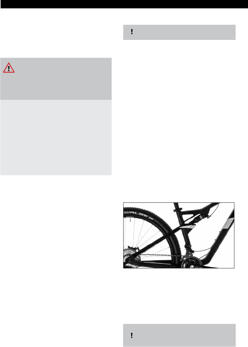
Bicycle racks may only be tted to moun-
ting elements intended for this purpose
(see picture below) from the following
series/models.
– Cross
– Trekking/City
– MTB with mounting option intended
for this purpose
•
Child seats may only be tted to suitable
bicycle racks. Please consult your specialist
dealer on this matter.
•
The maximum additional load amounts to 25 kg.
WARNING:
Some bicycle racks have only been appro-
ved for lower loads.
Please refer to the specications provided
by the manufacturer of the bicycle rack.
•
Find where this section is and following
lines: Admissible total weight even with your
children and/or luggage(see chart in chapter
3.2).
•
Ensure a safe loading. No item of the lug-
gagemay come in touch with the moving
bicycle parts (road wheel, drive, chain,
brakes) or may interfere with the functions
or the handling of your bicycle.
•
Do not exceed the admissible total weight,
see chapter 3.2.
•
Determine the admissible total weight by
lifting your bicycle up, including the entire
additional load (not including your children)
and the weight of y Make sure that you do
not reach the our bicycle clothing, and by
standing on an ocially calibrated scale
while lifting your bicycle up.
•
Please determine the weight of the children
by using bathroom scales and add their
weights to the total weight.
•
•
•
•
Additional loads will aect the bicycle’s
riding behaviour.
Additional loads will result in a longer
braking distance.
Adjust your riding style accordingly!
The tting and use of bicycle trailers on
our bicycles is not allowed, provided they
have not been specically approved for
the respective bicycle model.
2.1.7 Roller training
Risk of Personal Injury and Material
Damage!
Roller training:
The use of roller trainers that are xed
tightly to the frame, the handlebar or the
fork can damage your bicycle.
The use of roller trainers which are xed
tightly to the bicycle’s fork, handlebar or
frame is not allowed.
•
Have all tting of parts, modications, ser-
vicing and any other work carried out solely
by your specialist workshop.
•
Please note that the person who modies
the bicycle is also liable for them.

|
15
MTB/ ROAD BIKE/ TREKKINGMTB/ ROAD BIKE/ TREKKING
2.2 Other hazards
2.2.1 Hazards caused by faulty nal
assembly
Risk of Personal Injury and Material
Damage!
Failure to observe the instructions con-
tained in this Owner's Manual may result
in dangerous riding situations, falling,
accidents and material damage.
Have correct nal assembly and adjust-
ment of the right seat position for you
conrmed by your dealer. Use the printed
form in this Owner‘s manual on.
2.2.2 Hazards caused by improper use
Risk of Personal Injury and Material
Damage!
Failure to observe the instructions con-
tained in this Owner's Manual may result
in dangerous riding situations, falling,
accidents and material damage.
•
•
Please observe the instructions set out in
chapter 2.1.3
Always check if your bicycle meets the requi-
rements for its intended use (see chapters
2.1, 4.1.
2.2.3 Risk of burns
Risk of Personal Injury and Material
Damage!
Risk of burns!
After long descents, the bicycle rims and
brake disks can get very hot.
•
Do not touch the rims or brake disks imme-
diately after a descent.
2.2.4 Other hazards and safety notes
Risk of Personal Injury and Material
Damage!
Failure to observe the instructions con-
tained in this Owner‘s Manual may result
in dangerous riding situations, falls, acci-
dents and material damage.
•
Comply with the applicable trac regulati-
ons of your country.
•
Wear a helmet when cycling.
•
Look out for any possible dangers when
cycling, be alert and bear your own safety
in mind.
•
Do not cycle under the inuence of alcohol.
•
Cycle in a manner that ensures you have
control of the bicycle at all times and that
you will not get into diculty in sudden
dangerous situations.
•
When cycling make sure that you wear suita-
ble clothing that does not restrict the opera-
tion of the bicycle or impair your vision.
•
Wetness can aect the eciency of the bra-
kes. The braking distance is increased.
•
Only cycle wearing tight-tting leg wear.
Baggy clothing can get caught in the bicycle
and lead to serious accidents.
•
Do not exceed the admissible total weight,
see chapter 3.2.
•
Please refer to the care and maintenance
information in sections 12 and 13.
Carbon frames are generally only suitable
for use on a free roller trainer
(no xing).
•
Let the rims and brake disks cool down
before you touch them.
•
In order to check the temperature, touch
the rims and brake disks very briey with
your bare nger. If they are hot, wait a few
minutes and repeat the test until the rims
and brake disks have cooled down.

16
|
MTB/ ROAD BIKE/ TREKKINGMTB/ ROAD BIKE/ TREKKING
3 Scope of Supply,
Technical Data
3.1 Scope of supply
•
Complete bicycle, partially without
pedals or
•
Frame set
including the Owner’s Manual and delivery
certicate as well as all other relevant inst-
ructions of manufacturers whose parts were
used for the bicycle.
In case of carbon frames or pedelecs, please
observe the instructions set out in the addi-
tional Owner’s Manual.
3.2 Technical data
Admissible total weight
=
Bicycle including entire additional load
and attachment parts
+
Body weight incl. clothing and
luggage(e.g. backpack or laguage bag)
Risk of Personal Injury and Material
Damage!
New technical ndings can result in chan-
ges to the models, their technical data
and even in entirely new models.
•
Please observe the separate instructions,
if available.
•
Please consult your specialist dealer regar-
ding the currentness of this technical data.
(*): 12“/16“/18“/20“/24“ or 26“ indicates
the wheel size. This is indicated on the
tyre. Please consult your dealer.
Please note that the use of light-weight
components, e.g. special wheels, will redu
-
ce the load carrying capacity of the whole
bicycle.
For further information, please refer to
the parts instructions provided by the
respective manufacturer.
Example 1:
Wheel sets for a racing bike with an admis-
sible total weight of 90 kg will decrease the
admissible total weight of the racing bike
from 115 kg to 90 kg.
Example 2:
Bicycle racks with an admissible total weight
of 20 kg will decrease the admissible weight
of the trekking bike from 140 kg to 135 kg.
2.3 Disposal
Dispose of your bike properly at the end
of its life.
Ask your dealer or contact a recycling
centre
Risk of Personal Injury and Material
Damage!
Spinning wheels can injure your hands
and other body parts.
•
Keep your hands and other body parts away
from spinning wheels!
•
Keep your hands and other body parts away
from moving parts (e.g. suspension, steering
lever, brakes, etc.)!
•
Make sure that children sitting on any child
seats which may have been tted can not
touch any spinning wheels or moving parts.
Permissible total weight
Road racing / Triathlon / Time
trial /Cyclocross (incl. Hybrid)
115 kg
Mountainbike (MTB)
115 kg
Mountainbike Hybrid
125 kg
Trekking / Crossbike / Fitness-
bike / Urbanbike (incl. Hybrid)
115 kg + 25 kg
(on carrier)
Child‘s bike
12“ (120) *
30 kg
Child‘s bike
16“ (160) *
30 kg
Child‘s bike 1
8“ (180) *
40 kg
Child‘s bike
20“ (200) *
40 kg + 10 kg (on carrier)
Child‘s bike
24“ (240) *
(incl. Hybrid
80 kg + 10 kg (on carrier)
Child‘s bike
26“ (260) *
90 kg + 10 kg (on carrier)

|
17
MTB/ ROAD BIKE/ TREKKINGMTB/ ROAD BIKE/ TREKKING
You will nd the category and model as
well as further information relating to your
bicycle in the delivery certicate at the end
of this Owner's Manual.
When you make the purchase, please check
if everything has been lled out completely
and correctly with the help of your bicycle
dealer.
4 Assembly and function
4.1 Categories / Model Overview
We divide our bicycles into the following
categories. Within these categories, there are
dierent series.
3.3 Torques, screw connections
Part Manufacturer Model/Type Connection
Type of
connection
Tightening torque (Nm)
Seat post
CUBE
Performance
Post
Clamping
Saddle
2 screws 7
Performance
Motion Post
2 screws 7
ProLight
1 screw
+ 1 handwheel
8-10
AERO ProLight 2 screws 8-10
Dropper Post 2 screws 8-10
RFR
Suspension
Seatpost
2 screws 7-9
Level 9 Seatpost 2 screws 7
Ritchey
WCS Carbon
Single Bolt
1 screw 12
Syntace P6 Carbon 2 screws 8-10
Rock Shoxs Reverb Stealth 2 screws 10
CUBE AERIUM C:62
Clamping
standard saddle
1 screw 6
Clamping
Monolink saddle
2 screws 8
Carbon seat post
Clamping seat
post
on frame
1 screw
max. 6
(Apply torque gradually!)
Consider torque information
on seat post or inside seat post
manual!
Aluminium frame 1 screw 5-8
AERIUM HPA (aluminium frame) 2 screws 4-5
Carbon frame 1 screw
max. 6
(Apply torque gradually!)
AERIUM C:62 / C:68 (Carbon) 1 screw 6
Bottle cage assembly 2 screws 3
Cable guide assembly 1 screw 1,5
Carrier assembly per screw 6

18
|
MTB/ ROAD BIKE/ TREKKINGMTB/ ROAD BIKE/ TREKKING
4.1.3 Fitness bike/ Urban bike/ Category 1
Additional features:
Not equipped in accordance with StVZO, derailleur or hub
gear, wheels with rim diameter of 28 inches (622 mm).
- straight handlebar or handlebar
similar to mountain bike
- tyre with 25 mm to 42 mm
- rim or disc brakes
4.1.1 Children‘s Bikes / Category 0
Children‘s bicycles are mountain bikes with front suspension whose range of application is
dened by the spring travel and equipment. heels with rim diameter of 12“, 16“, 18“, 20“, 24“
and 26“ inches the range of application (see chapter 2.1.3) must be dened with your speci-
alist dealer.
4.1.2 Racing bike / Triathlon and time trial bikes / Category 1
Additional features:
Not equipped in accordance with StVZO, derailleur gear, rim
breaks, road wheels with rimdiameter of 28 inches (622 mm)
- tyre with 21 mm to 28 mm
- rim or disc brakes

|
19
MTB/ ROAD BIKE/ TREKKINGMTB/ ROAD BIKE/ TREKKING
4.1.4 Cross bike / Category 2
Has the same equipment characteristics as mountain bikes, wheels with a rim diameter of
28 inches (622 mm) and a tyre width of up to 50 mm.
4.1.5 Trekking bike/ Trekking bike HYBRID/
Category 2
Additional features:
Equipment in accordance with StVZO,
equipped with derailleur or hub gear,
rim brakes, backpedal brakes or disk
brakes, bicycle rack, splashguard
(“mudguards”),wheels with rim diameter
of 28 inches (622mm).
– tyre width of up to 55 mm
– lighting equipment, reectors and bell
4.1.6 Cyclocross/ Category 2
Not equipped in accordance with
StVZO, derailleur gear, road
wheels with rim diameter
of 28 inches (662mm).
Additional features:
- lug tyres
- disc brakes
4.1.3 Fitness bike/ Urban bike/ Category 1
Additional features:
Not equipped in accordance with StVZO, derailleur or hub
gear, wheels with rim diameter of 28 inches (622 mm).
- straight handlebar or handlebar
similar to mountain bike
- tyre with 25 mm to 42 mm
- rim or disc brakes
4.1.2 Racing bike / Triathlon and time trial bikes / Category 1
Additional features:
Not equipped in accordance with StVZO, derailleur gear, rim
breaks, road wheels with rimdiameter of 28 inches (622 mm)
- tyre with 21 mm to 28 mm
- rim or disc brakes

20
|
MTB/ ROAD BIKE/ TREKKINGMTB/ ROAD BIKE/ TREKKING
4.1.8 Fully/ Fully HYBRID (Full suspension mountainbike with max. 160 mm travel)
Category 4
Fullys are mountain bikes with front and rear wheel suspension whose range of application is
dened by he spring travel and the equipment. The range of application (see chapter 2.1.3)
must be dened together with your specialist dealer.
4.1.7 Hardtail/ Hardtail HYBRID/ MTB with suspension forkl/ Category 3
Hardtails are mountain bikes with front suspension whose range of application is dened by
the spring travel and equipment. The range of application (see chapter 2.1.3) must be dened
with your specialist dealer.

|
21
MTB/ ROAD BIKE/ TREKKINGMTB/ ROAD BIKE/ TREKKING
4.1.10 Dirtbike/ Downhillbike (Full suspension mountainbike with max. 215 mm
travel)/ Category 6
Dirtbikes bikes are mountain bikes with front wheel suspension/ Downhill bikes are
mountain bikes with front and rear wheel suspension whose range of application is dened
by the spring travel and the equipment. The range of application (see chapter 2.1.3)
must be dened together with your specialist dealer.
4.1.9 Fully MTB (Full suspension mountainbike with max. 170/190 mm travel) /
Category 5
Fullys are mountain bikes with front and rear wheel suspension whose range of application is
dened by the spring travel and the equipment. The range of application (see chapter 2.1.3)
must be dened together with your specialist dealer.
22
|
MTB/ ROAD BIKE/ TREKKINGMTB/ ROAD BIKE/ TREKKING
4.2 General information
4.2.1 Brakes
Your bicycle is equipped with one or two
independently-operated rim or disk brakes
(see chapter 4.1.1 - 4.1.10).
Risk of Personal Injury and Material
Damage!
Incorrect operation of the brakes can
lead to dangerous riding conditions, falls,
accidents and material damage.
•
Familiarise yourself with the operation of
the brakes.
•
Determine which brake lever operates the
front brake and which one operates the
back brake.
•
Operate the respective brake lever several
times in the static position. You can observe
an opening and closing action of the brake
blocks or brake calipers on the respective
disk or rim.
4.2.2 Gear shift
Your bicycle is equipped with
•
a derailleur gear and a crank set with one,
two or three chainwheels. This gear shift will
provide you with the optimal gear for every
speed speed and will, for example, enable
you to ride uphill more easily.
•
This is how you can determine the number
of gears: Derailleur gear: Multiply the
number of the front chainwheels with the
number of sprocket wheels in the back,
e. g. 2 chainwheels x 10 sprocket wheels =
20 gears.
•
Hub gear: Please take the indication on
the hub shell or on the gearshift lever into
account.
4.2.3 Frame and fork
Bicycle frames are available in the
following versions:
• without suspension: rigid fork and rigid
frame, available for the following series
- Children‘s bike 120/160/180 SL/200/
200 SL/240 SL
- Racing bike
- Cyclo-cross
- Fitness/Urban/SUV
- Trekking (not all models)
• semi-suspended (“hardtail”): with suspension
fork and rigid frame, available for the
following series
– Mountain bike
– Children‘s bike 240/260
– Cross
– Trekking (not all models)
• fully-suspended (“Fully” or “Full Suspension”):
with suspension fork and rear wheel
suspension.
There are dierent suspension systems with dif-
ferent numbers of joints for bicycles with full sus-
pension.
4.3 Frame material / information
on carbon material
Modern bicycle frames consist of aluminium alloys,
carbon, steel or titanium.
You can nd your frame material under
point 16, in the handover certicate, or by
consulting your specialist retailer.
four-joint frame
You can easily count the number of joints. The support
for the spring element is not considered a join.

|
23
MTB/ ROAD BIKE/ TREKKINGMTB/ ROAD BIKE/ TREKKING
Risk of Personal Injury and Material
Damage!
Carbon is a modern material used in bi-
cycle and vehicle construction. However,
carbon components are highly sensitive.
Errors in its assembly or use could lead
to breakages and therefore dangerous
driving conditions, falls, accidents and
material damage.
•
It is imperative that you observe all of the
following information regarding the use of
carbon parts.
•
Should you have any questions relating to
the use of carbon parts, please consult your
specialist retailer. Risk of personal injury and
material damage!
Risk of Personal Injury and Material
Damage!
Shock and impact loads which may occur
as a result of unintended use (see chapters
2.1.3 and 4.1) or stone-chipping, may lead
to inconspicuous damage in the carbon
bres and/or delamination (= a dissoluti-
on of the bonded carbon layers).
Such damage, combined with the forces
arising from the operation of the bicycle
can suddenly break carbon parts and
therefore lead to dangerous driving
conditions, falls, accidents and material
damage
•
Your bicycle must be used solely for the in-
tended purpose (see chapters 2.1.3 and 4.1)
•
After falls or other major mechanical stresses
which are not prescribed under normal
biking operations, carbon frames and com-
ponents should no longer be used.
•
Please consult your authorised specialist
retailer immediately after a fall.
Carbon is a more commonly used term for carbon-
bre reinforced plastic. This describes a bre-plastic
composite material in which the carbon bres are
embedded in several layers in a plastic matrix.
4.3.1 Information on frame
construction
These high-end products are produced by hand.
Deviations in nish may therefore occur, however,
this does not represent grounds for complaint.
4.3.2 How to use your carbon
parts correctly
1. Do not, under any circumstances, mount
brackets, screws, clamps or other ele-
ments which exert mechanical pressure
on the carbon tube.
2. Clamping onto bike stands or other wall
brackets:
•
Never clamp your bicycle to a carbon tube
or carbon seat post in the clamping jaws of
a bike stand.
3. Please take care when using shackle
locks! These may, under certain circum-
stances, damage your frame.
•
When using shackle locks, please ensure
that these only touch the respective carbon
tube at very the most, and are not exerting
pressure.
4. Saddle clamp / seatpost:
•
The prescribed tightening torque of the
saddle clamp bolt is max. 6 Nm.
•
The seat tube must not be scoured or me-
chanically processed in any other way.
•
Please consult your authorised specialist
retailer immediately after a fall.
•
The seatposts and seat tubes must not be
lubricated. Only a carbon assembly paste
may be used.
•
Aluminium seatposts may only be mounted
using a carbon assembly paste.
•
The seat clamp may not be closed if the seat
post has been removed.
5. Bottle holder:
•
The thread sets are provided for attaching
standard bottle holders. The maximum tigh-
tening torque of the screws for attaching the
bottle holder to the frame is 3 Nm.

24
|
MTB/ ROAD BIKE/ TREKKINGMTB/ ROAD BIKE/ TREKKING
6. Bicycle rollers
•
The use of bicycle rollers with xed clamps is
not permitted. By rmly restricting the drop-
outs and quick-release hub axles, mechanical
stresses occur which strongly exceed those
permitted for normal cycling operations. This
may result in damage to the bicycle frame.
7. Transport:
•
Due care must be taken when transporting
wheels with carbon frames.
•
The frame should particularly be protected
against contact with other parts using a cover
for example.
•
No carrier or other such systems which use
clamping elements for xing and mounting
may be used. These clamping forces may lead
to damage of the tubes or dropouts.
•
Do not place any objects on the frame.
•
Please ensure that the bicycle is in a xed and
stable position during transport.
5 Bicycle frame /
Bicycle frame set
Risk of Personal Injury and Material
Damage!
Incorrect mounting of the frame may
result in severe falls!
You can purchase some of our bicycle
frames separately and can have them
assembled according to your individual
wishes. Please make sure you consider the
following important notes.
•
The assembly of our frames may only be car-
ried out by specialist dealers that have been
authorised by us.
•
The person building the frame into a comple-
te bicycle is considered to be the manufac-
turer and is liable for any possible assembly
faults and defects.
• This Owner’s Manual is not an assembly
instruction for your bicycle frame.
• Only use trademarked equipment that has
been certied according to ISO standards
and is suitable for this frame for the assembly.
You can recognize the right equipment in
the supplied documentation if the following
information is present:
- manufacturer information with complete
address.
- information regarding conducted inspec-
tions and inspection guidelines with
ISO number.
- detailed and clear product information and
assembly notes in your national language.
• If you have questions regarding suitable
accessories, please consult your specialist
dealer.
• Please consider the information regarding
front forks in chapter 2.1.5
Risk of Personal Injury and Material
Damage!
- Racing bike, all models
- Fitness / urban, all models
- Cyclo-cross, all models
- Trekking with rigid fork geometry,
all models
- KID 120/160/180 SL/200/ 200SL/200
Ella/240 SL/240 Ella

|
25
MTB/ ROAD BIKE/ TREKKINGMTB/ ROAD BIKE/ TREKKING
2. Only use this bike when your dealer has
familiarised you with your bike‘s technical
features in a brieng.
3. Seal you bike with aerosol wax polish,
see Chapter 11.
4. Before riding your bike for the rst time,
please also read Chapter 8.
6 Before using for the rst time
Risk of Personal Injury and Material
Damage!
An unroadworthy bike can lead to dange-
rous riding conditions, falling, accidents
and material damage. This same danger
exists if you are not yet familiar with your
new bike and its controls.
•
Check your bike in accordance with point 7.
•
Familiarise yourself with this bicycle before
you rst ride it. In particular, check which
brake lever operates the front brake and
which the rear – see Section 4.2.1
•
Modern brakes have a very powerful braking
eect. Excessive pressure on the brake levers
can cause the respective wheel to lock and
can therefore cause you to fall.
Familiarise yourself slowly with the braking
eect on your bike in a safe area of land.
•
In a safe location, slowly test and become
accustomed to your bicycle’s braking
response
•
With new rim brakes and after replacing
brake blocks, the full braking eect only
develops after a certain run-in period. Please
therefore note that your braking distances
will initially be longer.
•
Disk brakes need to be initially run in.
Full braking eciency only develops after
the running-in process. Please note the
enclosed brake manufacturer‘s running-in
instructions.
•
If your bike is tted with optional click-in
pedals, which rmly connect the shoe with
the pedal, practise using them by mounting
and dismounting. Click-in pedals are not
safety pedals.
•
If after purchasing you remove the saddle
support and front and/or rear wheel for
transportation, please follow the appropria-
te instructions in Chapter 11.
1. Have your dealer conrm that the nal
assembly of your bike has been car-
ried out correctly and that your bike is
roadworthy. Have your dealer adjust the
correct saddle position.
You can make ne adjustments and minor
changes yourself as described in Chapter
8.2 and 8.3.
7 Before every trip
Risk of Personal Injury and Material
Damage!
An unroadworthy bike can lead to dange-
rous riding situations, falling, accidents
and material damage
Also consider the possibility that your
bike may have fallen over when unatten-
ded or that someone might have tam-
pered with it.
•
Check that your bike is roadworthy before
every trip.
•
Memorise your bike‘s actual condition when
new so that you will later be able to recog-
nise deviations from the actual condition
(photos you take yourself can be
a valuable aid).
•
Contact your specialist dealer immediately
if you discover that the actual state of the
bicycle deviates from its specied condition.
•
Only ride your bicycle again if it has been
properly repaired by the specialist dealer.
The parts described in the next subchap-
ters are not built into all bicycles. Some
parts may also have been retrotted.
Determine the equipment of your bike
with the help of the information in chap-
ter 4 and the following pictures. Carry out
the corresponding inspections.

26
|
MTB/ ROAD BIKE/ TREKKINGMTB/ ROAD BIKE/ TREKKING
Front and rear wheels are both called
road wheels.
A road wheel consists of :
•
the hub
•
On the rear wheel hub only sprocket or
sprocket cassette
•
Brake disk, if tted,
•
Spokes
•
Rim and the tyre equipment, which in turn
consists of
- Tyre casings
- Tube
- Rim tape insert
Currently, there are three dierent types
of tyre:
Wired-on tyres or folding tyres: This most
common type of tyre consists of the fol-
lowing components:
•
tyre
- If there are any loose parts:
- rim tape (only for rims with spoke holes)
Inside the tyre, there is a wire or a pad that
attaches itself to the rim ange when the
tyre is inated.
Field of application: All categories.
If you are unsure or if you have questions,
please consult your specialist dealer.
Only ride the bike again after it has been
properly readjusted by the dealer.
1. Visually inspect the whole bike:
•
Check all xing screws for correct tightness
(see Chapter 3.3)
•
Check the entire bike for dents, ruptures,
deep scratches and other forms of mechani-
cal damage.
2. Contact your dealer if visual inspections
show defects of any description.
7.1 Check the road wheels
•
Tubeless tyres:
Special rims (with or without hermetically
sealed spoke holes) and tyres form an
airtight seal and make the use of a tube un-
necessary. However, a tube can still be tted
in the event of a breakdown.
Field of application:
Mountain bikes, cross bikes, racing bike/
street.
•
Tubed tyres:
The tube is sewed into the tyre. During
assembly, the tyre including the tube is
glued to a rim specically designed for this
purpose. The assembly instructions of the
tyre, glue and rim manufacturers must be
observed in this context. Please also consi-
der the notes in chapter 7.1.3.
Field of application: Racing bike/street
Information on the type of tyre and the tyre
size is provided in chapter 16, in the delivery
certicate, or can be obtained by consulting
your specialist dealer on this matter.
Bicycles which are equipped according to StVZO
may be tted with rim reectors.
|
27
MTB/ ROAD BIKE/ TREKKINGMTB/ ROAD BIKE/ TREKKING
7.1.1 Check tting
1. Shake both road wheels vigorously at
right angles to the direction of travel.
-
-
-
The road wheels must not move in the forks.
The quick release must be closed (see
Chapter 8.8).
There must be no audible creaking or
rattling sounds.
2. Contact your dealer if this check shows
defects of any description
7.1.2 Check the rims
Risk of Personal Injury and Material
Damage!
Worn rims and/or substantial warping or
run-outs may lead to dangerous riding
conditions, falling, accidents and material
damage.
•
Worn rims must be replaced and warping or
run-outs repaired!
Risk of Personal Injury and Material
Damage!
With rim brakes: Dirty rims may reduce
braking eciency.
•
Dirty rims must be cleaned immediately.
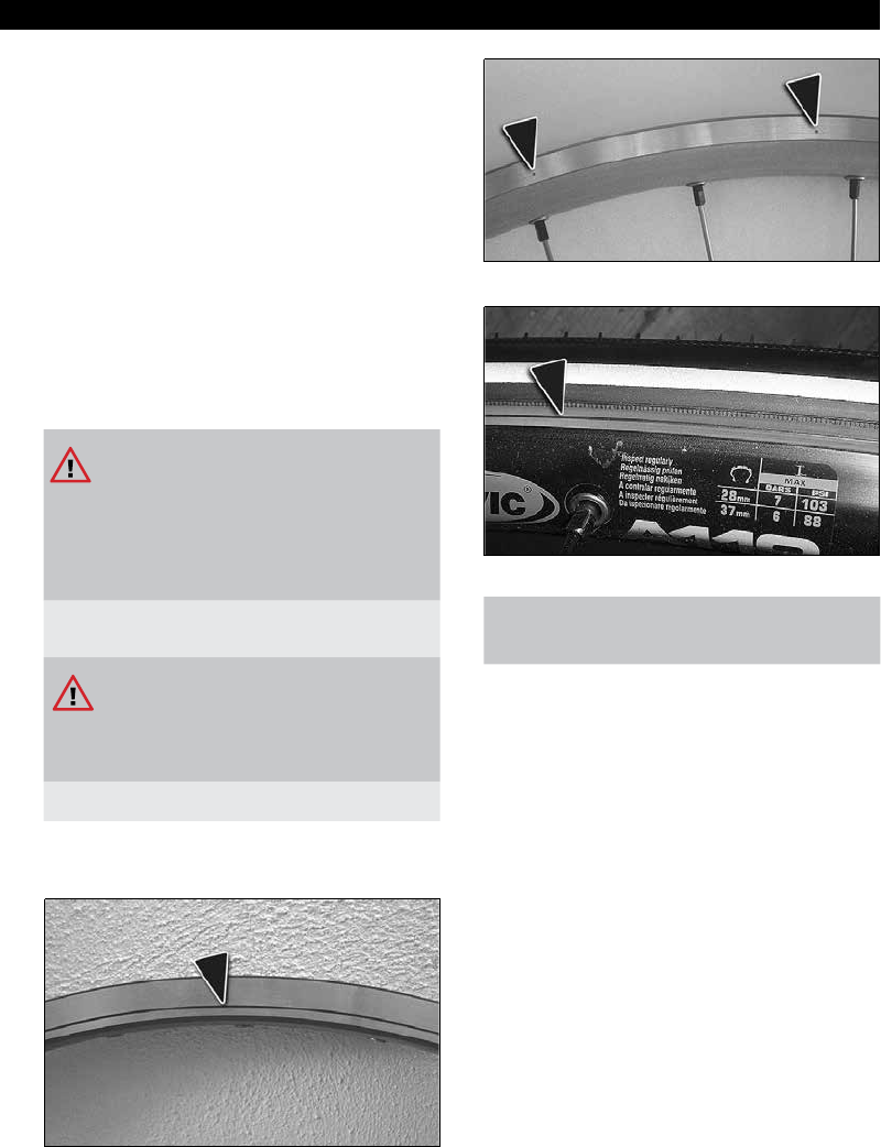
1. Check rims for wear:
Rims with wear indicators:
Visual check
Rims without wear indicators:
Visual check
•
Fingernail check: Run your ngernail ac-
ross the rim shoulder. No scoring should
be felt.
•
If the wear indicator is no longer visible
or if the rim has discernible scoring, the
rim must be replaced.
2. Check rims for run-out:
•
Lift the bike up and spin rst the front
and then the rear wheel.
•
Note the distance between the rim and
the brake shoes and on disk brakes the
distance between the rim and the frame
strut or fork leg. The maximum permis-
sible deviation per rotation amounts to
2 mm.
3. Check your rims for dirt, especially oil
and grease.
Dirty rims must be cleaned immediate-
ly (see Chapter 12).
Wear indicator
28
|
MTB/ ROAD BIKE/ TREKKINGMTB/ ROAD BIKE/ TREKKING
7.1.3 Check tyres
Risk of Personal Injury and Material
Damage!
Does not apply to tubeless tyres.
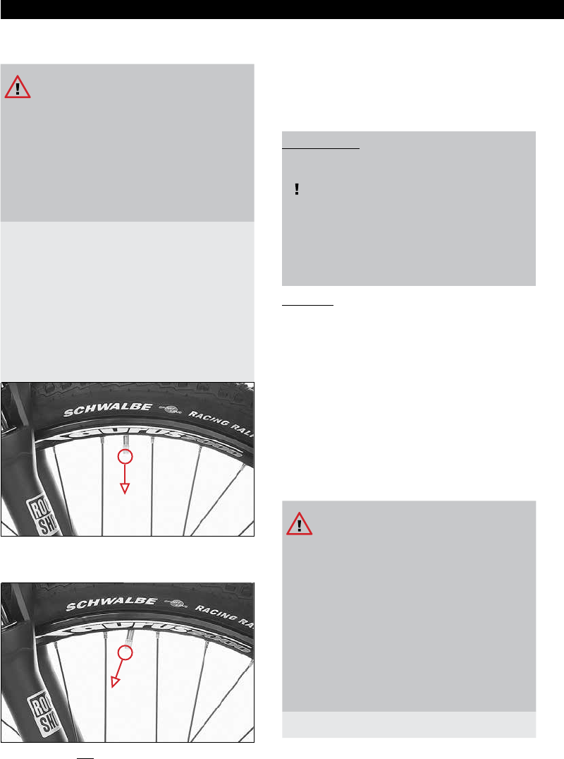
If the valve is angled, the base of the
valve can rip o when riding which causes
sudden loss of tyre pressure.
This can lead to dangerous riding con-
ditions, falling, accidents and material
damage.
•
Have the tyre seating corrected by a specia-
list workshop.
You can undertake this job yourself if you are
familiar with tting and removing the road
wheels (see Chapter 11.1) and replacing the
tyre and tube.
•
Remove the valve nut.
•
Check the valve position:
The valves must point directly towards the
centre axis of the road wheel.
The valves must point directly towards the centre
axis of the road wheel.
Risk of Personal Injury and Material
Damage!
Too low a tyre pressure leads to increa-
sed likelihood of punctures but mostly
dangerous handling.
The tyre can come o the rim on bends
and cause the tyre to become detached
from the rim.
This can lead to dangerous riding con-
ditions, falling, accidents and material
damage.
•
Inate your tyres to the correct pressure.
The valve does not point to the traversing wheel
centre
Check the tyre pressure:
1. Determine your tyre type
Mountain bikes can be tted with racing bike type
tyres and racing bikes with trekking tyres.
Rule of thumb:
Mountain bike tyres:
Tyre width greater than 40 mm
Trekking / cross-country and
tness bike tires:
Tyre width from 25 mm – 42 mm
Racing bike style tyres:
Tyre width from 21mm - 28 mm
Consult your dealer to determine your tyre
type.
Pressures:
• Mountain bike tyres: 2.5 – 3.5 bar
• FAT bike tyres: 0.7 – 2.0 bar
• Trekking and city bike tyres: 3.5 - 5.0 bar
• Racing bike tyre: 6.0 - 10.0 bar
• For the correct air pressure for categories
not listed here, please refer to the infor
mation on the tire or consult your dealer.

|
29
MTB/ ROAD BIKE/ TREKKINGMTB/ ROAD BIKE/ TREKKING
psi 30 40 50 60 70 80 90 100 110 120 130 140
bar 2.1 2.8 3.5 4.1 4.8 5.5 6.2 6.9 7.6 8.3 9.0 9.7
The actual permissible tyre pressure can be
found in the tyre and rim manufacturer‘s
instructions. The permissible tyre pressure is
mostly embossed on the tyre wall. Please
consult your dealer.
The higher your body weight, the higher
the tyre pressure needs to be.
Check the tyre pressure with a tyre pressure
gauge. Simple gauges are often included with
bicycle tubes and higher quality gauges are
available from your dealer.
How to use them is detailed either in the
instructions for use or you can have your
dealer demonstrate this.
- If pressure is too low: Increase the pressure
by inating with a suitable pump.
- If pressure is too high: Release sucient air
via the valve and check the pressure again
afterwards with a gauge.
2. Check your tyres for external damage and
wear:
•
The tyre rubber must have the same pattern
as the original over its entire surface.
•
The tyre canvas beneath the layer of rubber
must not be visible.
•
There must be no bulges or tears.
3. Check the t of your tyres:
•
Lift the front or rear road wheel and turn it
by hand.
•
The tyre must rotate through 360 degrees.
There must be no highs or lows.
7.1.4 Other checks
1. Check your road wheels for loose items
such as, for example, pieces of branches,
residues, loose spoke reectors etc.
If there are loose parts:
•
Remove these if this is possible without
applying any great force.
•
Check if your road wheels have been dama-
ged by these loose items.
•
Tighten loose bicycle parts such as spoke
reectors, for example. If you nd this is not
possible, contact your dealer immediately.
•
Please note that all reectors are present in
accordance with StVZO (see Chapter 2.1.4),
correctly secured and not obscured or dirty.
Many tyre pressures are given in "psi". Convert the pressure using the following table.
Using a bicycle pump with a pressure
gauge, you can check the pressure whilst
inating the tyre.
Let some air out of the tyre rst and then
increase the pressure to the desired level.
There are various types of valve. All
valves can be tted with a dust cap.
After removing the cap, you can place the
pump head directly on the valve in either
a Schrader (Auto) valve or what is known
as a express valve (Dunlop). In the case of
a Sclaverand (French) valve, you rst have
to loosen the small lock nut on the valve
as far as it will go, then tighten it again
completely after inating the tyre.
•
Get your dealer to demonstrate operation of
the valves to you.

30
|
MTB/ ROAD BIKE/ TREKKINGMTB/ ROAD BIKE/ TREKKING
7.2 Check saddle and seat post
Risk of Personal Injury and Material
Damage!
If the seat post is not inserted far enough,
the seat post can come loose.
This can lead to dangerous riding con-
ditions, falling, accidents and material
damage.
•
Note the correct seat post insertion distance.
Please read Chapter 8.3 for information.
If you have the requisite technical know-
ledge, you can tighten this yourself.
•
Please read Chapters 8.2, 8.3 and 11.2 for
information.
1. Check the saddle and seat post for tight-
ness:
Try to twist the saddle and seat post by
hand. It should not be possible to twist the
saddle and/or seat post.
Try to move the saddle in its clamp with
alternate up and down movements.
It should not be possible to move the saddle.
If either the saddle and/or the seat post can
be moved, tighten them (see Chapters 8.2,
8.3, and 11.2.
7.3 Check handlebars and stem
Risk of Personal Injury and Material
Damage!
The handlebars and stem are very impor-
tant components in terms of your riding
safety.
Damage to them and mistakes during
assembly can lead to very severe falls.
•
If you discover any faults with these parts or
have doubts about them, you must under
no circumstances continue to use your bike.
•
Contact a specialist workshop immediately.
1. Check the handlebar and stem assembly.
•
The stem must be parallel to the front wheel
rim
•
and the handlebars must be at right angles
to it.
•
In the case of a shaft stem, the "Max"
„or Stop" or similar marking must not be
visible.
•
Grip the front wheel betwween your legs.
•
Grip the handlebars at both ends.
•
Try to twist the handlebars in either direc-
tion by hand.
•
Try to twist the handlebars in the stem by
hand.

|
31
MTB/ ROAD BIKE/ TREKKINGMTB/ ROAD BIKE/ TREKKING
•
It must not be possible to twist or slide
any of the parts.
•
There must be no audible creaking or
rattling sounds.
7.4 Check handlebar-mounted parts
1. Check the gearshift/brake levers,
grips (straight handlebars only) and
triathlon rest (triathlon bikes only) for
correct t:
•
Grip the front wheel between your legs
or keep the handlebars steady with your
hand.
•
Try to twist the brake levers with your
other hand.
Triathlon attachment
•
Grip the front wheel between your legs.
•
Try to twist the gear levers using your
other hand.
•
Try to pull the handgrips and the bar
ends from the handlebars.
•
It must not be possible to twist or slide
any of the parts.
•
There must be no audible creaking or
rattling sounds.
•
In case a bell has been tted to the hand-
lebar, it must be possible to reach it easily
with a nger or a thumb and it must not
be possible to move it.
7.5 Check the forks bearing
The forks bearing is the forks bearing
in the fork stem.
1. Check your forks bearing. The front
wheel must swivel easily in both direc-
tions with no play:
•
Stand beside your bike and hold the
handlebar grips with both hands.
•
Pull the front brake lever and keep the
brake applied.
•
Push your bike forward and backward in
short, jerky movements.

32
|
MTB/ ROAD BIKE/ TREKKINGMTB/ ROAD BIKE/ TREKKING
•
There should be no play in the forks
bearing: no clicking should be heard or
felt. You should not hear creaking noises
either.
•
Lift the whole bike up so that the rear
wheel is higher than the front wheel.
•
Move the front wheel by steering to the
side and let it go again.
•
The front wheel must automatically
return to its original position.
•
The front wheel must not lock in any
position.
7.6 Check suspension forks
1. Check your suspension forks:
•
Pull the front brake lever and keep the
brake applied.
•
Press down on the handlebars with your
body weight so that the suspension forks
deect.
•
The forks must spring easily up and
down.
•
There must be no audible creaking or
rattling sounds.
•
Stick the front wheel between your legs
and try to pull the bicycle up using the
handlebars.
•
The standpipes mustn´t break loose from
the diving pipes or from the fork bridge.
•
Please regard the instructions for your
fork in the separate instruction manual.
7.7 Check the rear wheel suspension
1. Check your rear wheel suspension:
•
Sit on your bike and activate the sus-
pension in a standing position using
vigorous up and down movements.
•
The rear of the bike must spring up and
down easily.
•
There must be no audible creaking or
rattling sounds.
7.8 Check the brakes
Risk of Personal Injury and Material
Damage!
If the brakes malfunction, there is the risk
of loss of life.
•
Check your brake system particularly
carefully.
When touring for several days, the brake
disk, brake blocks and brake pads can
sustain a great deal of wear.
When touring like this, carry spare brake
blocks and replacement pads with you.
Only replace them yourself if you are
familiar with this task. Please consult
your dealer.
If you cannot replace them yourself, have
this done by a trained specialist.

|
33
MTB/ ROAD BIKE/ TREKKINGMTB/ ROAD BIKE/ TREKKING
1. Checking the function of your brake
system:
•
In a static position operate both brake levers
until the brakes make rm contact.
•
Please note that in this position the mini-
mum distance between the brake lever and
the handlebar grip must be at least 35 mm.
•
Try to push the bike with the brakes applied
in this way.
Both wheels must remain locked.
7.8.1 Check rim brakes with cable (racing
bike version).
1. Check the brake cables and their clips:
•
The brake cables must not be damaged or
corroded.
•
On cable brakes, the brake cables must be
securely clipped along their entire length.
Racing bike rimbrake
2. Check that the entire brake system has
been secured and screwed in correctly:
•
Try to pull the brakes from the forks (front)
and from the frame (rear) by hand.
•
It must not be possible to pull the brakes o
and there must be no play in the xing bolts.
3. Check the position of the brake shoes.
•
With the brake applied, the brake shoes
must be in contact with the rim shoulder
along their entire length.
•
Under no circumstances must the brake
shoes touch the tyre even when the brake is
not applied.
35mm

34
|
MTB/ ROAD BIKE/ TREKKINGMTB/ ROAD BIKE/ TREKKING
5.
Check centring of the brake shoes.
•
The brake shoes must be equidistant from
the rim on both sides.
7.8.2 Check rim brakes and cable
(mountain bike version).
1. Check the brake cables and their clips:
•
The brake cables must not be damaged or
corroded.
•
On cable brakes, the brake cables must be
securely clipped along their entire length.
2. Check that the entire brake system is
secured and screwed in correctly:
•
Try to pull the brakes out of the sockets by
hand.
•
It should not be possible to loosen the
brakes from the sockets by hand. A small
amount of play is normal.
3. Check operation of the brake shoes.
•
With the brake applied, the brake shoes must
be in contact with the rim shoulder along
their entire length.
4. Check the brake block wear.
•
Under no circumstances, must the brake
shoes touch the tyre even when the brake
is not applied. Unhinge the brakes (see
Chapter 11.1)
•
The brake pads must not be worn down in
excess of the degree shown by the wear
indicator.
5. Check centring of the brake shoes.
•
The brake shoes must be equidistant from
the rim on both sides.
4. Check the brake block wear.
•
The brake blocks must not be worn down
beyond the wear indicator.

|
35
MTB/ ROAD BIKE/ TREKKINGMTB/ ROAD BIKE/ TREKKING
7.8.3 Check hydraulic rim brakes
1. Check that the entire brake system is
secured and screwed in correctly:
•
Try to pull the brakes out of the sockets by
hand.
•
It should not be possible to loosen the
brakes from the sockets by hand.
A small amount of play is normal.
2. Check your brake system seals:
•
Operate each brake lever in a static position
and hold the brake lever in that position.
•
Check the brake system from the brake lever
along the wires to the brakes.
•
There must be no egress of hydraulic uid at
any point
3. Check the position of the brake shoes:
•
With the brake applied, the brake shoes
must be in contact with the rim shoulder
along their entire length.
•
The brake shoe must never touch the tyre –
even if the brake is not applied.
7.8.4 Check hydraulic disk brakes
Risk of Personal Injury and Material
Damage!
Dirty brake disks may reduce braking
eciency.
Dirty brake disks may reduce braking
eciency.
1. Pull the brake caliper alternately in all
directions.
•
It should not be possible to move the
caliper.
2. Check your brake system seals:
4. Check the brake block wear.
•
The brake blocks must not be worn down
in excess of the degree shown by the wear
indicator.
•
Operate each brake lever in a static position
and hold it.
•
Check the brake system from the brake lever
along the wires to the brakes.
•
There must be no egress of hydraulic uid at
any point.
3. Check brake disk for damage:
•
There must be no grooves, ruptures, deep
scratches or other mechanical damage.
4. Lift the front or rear road wheel and turn
it by hand:
•
The brake disk must only have a slight axial
run-out.

36
|
MTB/ ROAD BIKE/ TREKKINGMTB/ ROAD BIKE/ TREKKING
5. Have the degree of wear to the brake pad
and brake disk checked at a specialist
workshop (see also Chapter 11):
•
The brake pads must not be worn down in
excess of the degree shown by the wear
indicator.
•
The brake disk must not be less than the
minimum thickness.
•
The minimum thickness is specied in the
accompanying parts instructions.
6. Check your brake disks for dirt, especially
oil and grease.
•
Dirty brake disks must be cleaned immedia-
tely (see Chapter 11)
When touring for several days, the brake
disk, brake blocks and brake pads can
sustain a great deal of wear.
When touring like this, carry spare brake
blocks and replacement pads with you.
Only replace them yourself if you are
familiar with this task. Please consult
your dealer.
If you cannot replace them yourself, have
this done by a trained specialist.
7.8.5 Check back pedal brake
1. Ride your bike at walking pace.
2. Step "backwards" against the direction
of drive.
3. This makes the rear wheel brake sharply.
7.9 Check drive train and chain
1. Turn the right-hand crank counter anti-
clockwise and from above examine the
chain rings and the pinion cassette.
•
The chain rings and pinions must have no
axial run-out.
•
There must be no debris present. Remove
the latter if this is easy to do.
2. Press the left crank in the position shown
against the chain stay.
•
You should feel no internal play.
•
There must be no audible creaking or ratt-
ling sounds.
3. Check the chain for damage.
•
At no point on the chain should there be,
for example, any damaged chain side bars,
protruding rivet pins or xed and immobile
chain links.
4. In a static position, turn the right crank
against the direction of the drive and ob-
serve the running of the chain at the gear
change rollers on the change mechanism.
5. The chain must run smoothly over the
change rollers and must not jump.
7.10 Check lighting set
Risk of Personal Injury and Material
Damage!
Failure of the front headlight and the rear
light can lead to dangerous road condi-
tions in darkness and/or bad visibility.

|
37
MTB/ ROAD BIKE/ TREKKINGMTB/ ROAD BIKE/ TREKKING
•
Tilt the whole bike from side to side a few
times.
•
The xing struts must not loosen.
•
No part of the mudguards must touch the
wheels.
7.13 Other checks
Risk of Personal Injury and Material
Damage!
A side stand which has popped out during
a ride can result in serious falls. Always
retract the side stand before riding.
•
Always retract the side stand before riding.
1. Check your side stand, if tted.
•
Visually check screws and bolt xture.
Always retract the side stand before riding. The
side stand must be securely xed to the frame.
•
Always fold the side stand upwards before
riding. The stand must also remain in this
position if the bike jolts.
Risk of Personal Injury and Material
Damage!
A side stand that is bent, too short or too
long does not provide a secure stand for
your bicycle.
Your bicycle could fall over and injure you
or other people.
In addition, your bicycle and surrounding
objects such as other bicycles, cars, etc.
may get damaged.
7.12 Check splash guards (mudguards)
Risk of Personal Injury and Material
Damage!
Loose or untightened splash guard parts
can block the wheel and result in serious
falls.
•
Only use your bike again when the splash
guard has been attached by a specialist
workshop.
1. Check your "mudguard" xings.
•
The mudguard and its xing struts must not
be broken or damaged.
•
In a static position, move the front wheel
vigorously from side to side using the
handlebars.
•
Have bent side stands repaired or replaced
by a specialist workshop.
•
As for side stands with adjustable lengths:
have the correct length adjusted by a specia-
list workshop.
1. Check your side stand, if there is one.
•
Visually inspect the screw connection. The
side stand must be mounted securely on the
frame.
•
Fold the side stand up before every ride. The
side stand must not unfold by itself.
•
Only use your bike in such conditions if your
lighting system is fully functional.
1. Check your lighting system:
•
Please observe the on/o switch on the
headlamp if there is one.
•
Raise the front wheel.
•
Turn the front wheel vigorously by hand.
•
The front headlight and rear light must
function properly.
•
Please check that the rear light is functio-
ning correctly if there is one.
7.11 Check carrier
Risk of Personal Injury and Material
Damage!
Loose or untightened carrier parts can
block the wheel and result in serious falls.
•
Only use your bike again when the carrier
has been attached by a specialist workshop.
1. Shake the carrier from side to side by
hand. The carrier xings must not come
loose.
The carrier must not touch the tyre.
•
If there is one, check the sidelight behind to
ensure it is functioning.

38
|
MTB/ ROAD BIKE/ TREKKINGMTB/ ROAD BIKE/ TREKKING
8 Adjusting and servicing
your bike
You can modify your bike yourself.
Only make these adjustments yourself if
you have the appropriate technical know-
ledge and experience and the right tools
for the job.
8.1 Adjusting the adjustable stem
(optional)
•
Many bikes are tted with an adjustable
stem, the height and angle of which can be
adjusted. Only have the adjustment made in
a specialist workshop!
8.2 Adjust saddle position
Your saddle will be secured with one or two
clamping bolts.
To adjust it, you need a hexagonal socket of
the right size and a torque wrench.
1. To adjust the horizontal position or incli-
nation of your saddle:
•
Loosen the clamping bolt(s) a few turns until
the saddle can be turned easily and/or the
inclination angle adjusted.
Risk of Personal Injury and Material
Damage!
•
Damaged bicycle parts can have sharp edges
and injure you.
•
Check all the bike parts that you may come into
contact with while riding your bike.
•
Have damaged parts repaired or replaced
immediately by an authorised repair shop.
•
As for side stands with adjustable lengths:
check if the extendable part can be moved
by exerting hand force.
2. Check the secure stand of your bicycle.
•
Lean or place your bicycle on the unfolded
side stand.
•
Your bicycle must stand by itself.
•
When pushed slightly in any direction, your
bicycle must remain standing and not fall
over.
Risk of Personal Injury and Material
Damage!
Accessories that have not been tted
correctly or that have become loose can
jeopardise your safety when riding.
•
Check any accessory that is explicitly listed
herein to ensure that it has been secured
properly.
•
Immediately contact a specialist workshop
in case one of the following requirements is
not met.
3. Check any accessories that have been
retrotted.
•
Visually inspect the screw connections.
•
Try to twist or move the accessories out of
position by exerting hand force .
•
Tilt the whole bicycle against the direction
of travel and move it back and forth a few
times.
•
Lift your bicycle up (one or two centimetres)
and put it down again.
•
The accessories must not be loose, move or
twist.
•
No part of the accessories should touch the
wheels.
•
If tted, a bicycle stand should not be
unfolded.
•
There should be no noticeable noise.

|
39
MTB/ ROAD BIKE/ TREKKINGMTB/ ROAD BIKE/ TREKKING
•
Move the saddle to the desired position.
•
For seat clamps with only one xing screw:
always tighten the seat clamp with the
correct, prescribed torque. Make sure that
all loosened parts join together with the
correct alignment (see Chapter 3.3.).
•
For seat clamps with two xing screws:
tighten one screw just for a quarter or a half
turn then continue with the other screw
in the same way. Do this as long as you´ve
reached the right torque (see Chapter 3.3.).
•
Please observe the specied tightening
torques in table 3.3.
8.3 Adjust saddle height
Risk of Personal Injury and Material
Damage!
A saddle set too high for children who
are not yet able to cycle safely without
assistance, could result in dangerous
driving conditions, falls, accidents, and/or
property damage.
•
Adjust the seat height in such a way that the
child's feet can touch the ground when in a
sitting position.
•
On a gripper clamp with bolt, you need a
hexagonal socket and a torque wrench of
the correct size. For a quick-release clamp,
please see Chapter 8.8.
1. Loosen the clamp as described in
Chapter 11.2.
2. Move the saddle and saddle stem to the
desired position. Please note the inst-
ructions regarding saddle stem insertion
distance in Chapter 11.2.
3. Clamp the saddle stem as described in
Chapter 11.2.
8.4 Adjust suspension forks
1. Please read the instructions for adjusting
your suspension forks in the suspension
fork manufacturer‘s parts instructions.
2. If your forks have a xed adjustment
mechanism as shown in the illustration,
please read the related instructions in
the suspension fork manufacturer‘s parts
instructions.
Suspension forks with elastomers and/
or steel springs are only suitable for one
overall weight range (= weight of rider
+ any baggage). This weight range is
usually within 20 kg.
Only the forks pre-tensioning can be
adjusted by compressing the springs by
means of an adjuster screw. This merely
changes the initial breakaway torque of
the forks.
That is, with greater pre-tensioning, the
forks only deect at higher operating
forces.
If the forks are pre-tensioned too much,
suspension travel is accordingly less.
The weight range for which the suspen-
sion elements in your forks are suited
can be found in the fork manufacturer‘s
instructions and/or you can consult your
dealer.
If your total weight is outside this range,
have your dealer t suspension elements
matching your weight.

40
|
MTB/ ROAD BIKE/ TREKKINGMTB/ ROAD BIKE/ TREKKING
8.5 Adjust rear suspension
(on full suspension bikes)
1. Please read the instructions for adjusting
your suspension/damper elements in the
suspension fork manufacturer‘s parts
instructions. Please consult your dealer.
2. Adjust your suspension/damper element
so that the bike when carrying the rider‘s
weight deects equally at the front and
rear wheels.
8.6 Service the gears
Risk of Personal Injury and Material
Damage!
Incorrect operation of the gear shift le-
vers can damage your gears.
•
Never operate both levers or both gear shift
switches at the same time!
•
Please note that for the crank set (left-hand
lever) and hub gears: never shift if there is
a load!
1. Please determine which gear shift system
your bike has on the basis of the illustra-
tions,. If you are not sure which one it is
please consult your dealer.
2. If your gear shift lever is not shown in the
illustrations, please refer to the accom-
panying gear shift lever manufacturer‘s
instructions and/or consult your dealer.
Shimano Rapidre 2-Way-Release_Deore
Shimano Rapidre 2-Way-Release_XT
Twist Grip Shift
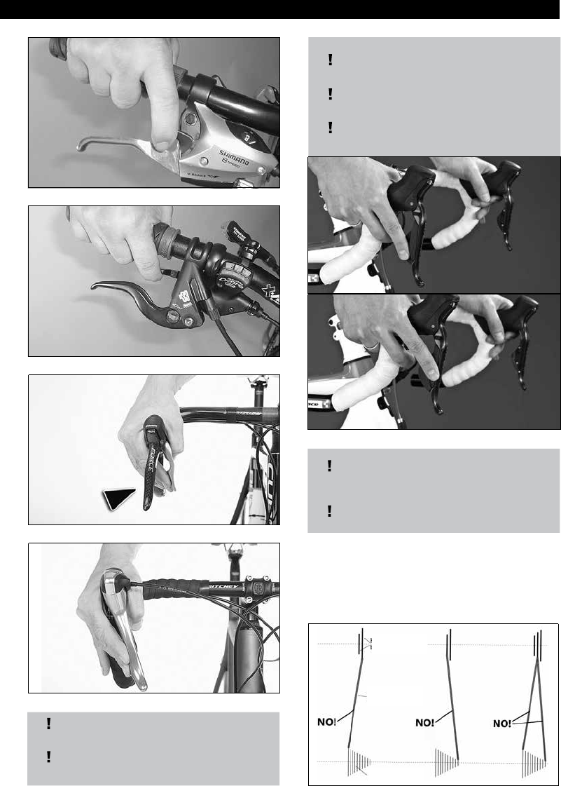
|
41
MTB/ ROAD BIKE/ TREKKINGMTB/ ROAD BIKE/ TREKKING
When using an electronic derailleur
gear (called Di2 by Shimano), the shif-
ting is done by pressing buttons.
The Di2 connection is analog.
For further information, please refer
to the specic operating instructions
provided by the manufacturer.
On derailleur systems, the gear is shifted
by switching the chain to another sprocket.
On the crank set, these sprockets are called
"chain rings" and on the rear sprocket
cassette they are called "pinions".
3. Please observe the chain position
prescribed as shown above.
•
To be avoided:
largest chain ring + largest pinion.
•
Smallest chain ring + smallest pinion.
Shimano EZ Fire
Shimano Rapidre
Sram Force / Rival / Red
Shimano STI
The STI connection is mechanical.
The left-hand lever operates the chain
ring derailleur and the right-hand lever
operates the gear shift.
Shimano Di2
chain ring
chain
pinion

42
|
MTB/ ROAD BIKE/ TREKKINGMTB/ ROAD BIKE/ TREKKING
Lever A
Lever B
1. Here is how you shift to a larger spro-
cket:
•
In order to shift, you must be pedalling.
•
Press the lever down with your thumb
beyond the rst stop and keep it de-
pressed until the desired gear is selected.
8.6.1 Shimano Rapidre/ Shimano
Rapidre 2-Way-Release/
Shimano EZ Fire
On your gear-shift there are two levers. Lever
A is for shifting to a larger chain ring or spro-
cket and Lever B for shifting to a smaller one.
•
For rapid shifting through several spro-
ckets, press the lever right down and
keep it depressed until the desired gear is
selected.
2. Here is how you shift to a smaller
sprocket:
•
In order to shift you must be pedalling.
•
Depress (2-Way-Release only) or pull Lever
B until you feel it engage and then release
it again straight away.

|
43
MTB/ ROAD BIKE/ TREKKINGMTB/ ROAD BIKE/ TREKKING
8.6.2 SRAM gear shift
On your gear-shift there are two levers. Lever
A is for shifting to a larger chain ring or spro-
cket and Lever B for shifting to a smaller one.
1. Here is how you shift to a larger sprocket:
•
in order to shift you must be pedalling.
•
Press the lever down with your thumb bey-
ond the rst stop and keep it depressed until
the desired gear is selected.
•
For rapid shifting through several sprockets,
press the lever right down and keep it de-
pressed until the desired gear is selected.
2. Here is how you shift to a smaller spro-
cket:
•
in order to shift you must be pedalling.
•
Depress Lever B until you feel it engage and
then let it go again straight away.
8.6.3 Twist grip shift
On your shift grip, there is a ring which can
be rotated in either direction. By turning this
ring you shift into the next gear.
Depending on the manufacturer, you shift
into a higher or lower gear in one direction
of rotation. Details of the precise functioning
can be found in the accompanying parts
instructions and/or consult your dealer.
1. Here is how you shift with hub gears:
•
pedalling in order to shift.
•
Turn the rotating ring in the desired direc-
tion until the gear is selected.
2. Here is how you shift with derailleur
gears: to a larger sprocket
•
in order to shift you must be pedalling.
•
Turn the rotating ring until the desired gear
is selected.
•
For rapid shifting over several sprockets,
turn the rotating ring until the desired gear
is selected.
3. Here is how you shift to a smaller spro-
cket:
•
in order to shift you must be pedalling.
•
Turn the rotating ring until the desired gear
is selected.
•
For rapid shifting over several sprockets,
turn the rotating ring until the desired gear
is selected.
B
A

44
|
MTB/ ROAD BIKE/ TREKKINGMTB/ ROAD BIKE/ TREKKING
8.6.4 Shimano STI
On your gear-shift there are two levers. Lever
A – this is also the brake lever - is for shifting
to a larger chain ring or sprocket and Lever B
is for shifting to a smaller one.
1. Here is how you shift to a larger sprocket:
•
In order to shift you must be pedalling.
•
Press Lever A down with your thumb bey-
ond the rst stop and keep it depressed until
the desired gear is engaged.
•
For rapid shifting through several sprockets,
press Lever A right down and keep it de-
pressed until the desired gear is engaged.
A
B
8.6.5 Sram Force / Rival / Red
On your gear shifter/brake lever, you will
nd a lever which can be used to switch to
both a lower and higher gear.
1. In order to switch to a higher gear, please
do the following:
•
To switch gears, you must pedal.
•
Press the gear shifter inwards and hold
down until the desired gear has been
selected.
•
To switch through several gears, press the
lever down fully and hold down until the
desired gear has been selected.
2. In order to switch to a lower gear, please
do the following:
•
to switch gears, you must pedal.
•
Press the lever until you feel it coming to a
stop and then let it go again.
2. Here is how you shift to a smaller spro-
cket:
•
In order to shift you must be pedalling.
•
Depress Lever B until you feel it engage and
then let it go again straight away.
A B

|
45
MTB/ ROAD BIKE/ TREKKINGMTB/ ROAD BIKE/ TREKKING
8.7 Service the brakes
Risk of Personal Injury and Material
Damage!
Incorrect operation of the brakes can lead
to dangerous riding conditions, falling,
accidents and material damage.
•
Familiarise yourself with the operation of the
brakes.
•
Ascertain which brake lever operates the front
and which one operates the back brake.
•
Operate the respective brake lever several
times in the static position.
You can observe an opening and closing
action of the brake blocks or brake cali-
pers on the respective disk or rim.
1. To operate the brake, pull the lever in the
direction of the handlebars.
You will obtain the best braking eect if
you operate both brake levers in a coordi-
nated and balanced manner.
8.8 Operate the quick-release action
Risk of Personal Injury and Material
Damage!
Incorrect mounting of the road wheels
on a quick-release hub axle may result in
dangerous riding conditions, falls, acci-
dents and material damage.
•
Read the following description regarding
the handling of your quick-release hub axle
and follow the instructions accordingly.
•
Familiarise yourself with the handling of the
quick-release hub axle.
•
Repeatedly practise mounting and demoun-
ting your road wheels to and from the quick-
release hub axle.
•
Check the road wheel every time after it
has been mounted to the axle following the
instructions in Chapter 7.1.1.
•
In case you are unsure if your road wheels
have been mounted correctly, do not ride
your bicycle and consult your specialist
dealer.
Risk of burns!
Quick-release levers on disk brakes can
become hot during riding.
•
Touch the quick-release lever very briey
with your nger.
If it feels hot, let it cool down.
Our bike hubs and possibly also your saddle stem
may have quick-release ttings (often also referred to
as "quick-release clamps" or simply "quick releases").
These quick-release ttings make it possible to di-
sassemble and assemble these components quickly
without any tools.
Construction and function.
•
Long-threaded axis with a nut on one side and
an excentrically-mounted lever on the other
•
There is a little spring between the nut and
hub and between the hub and the lever.
1
2
3
4
4
3: Lever
4: Spring
Legend:
1: Axle
2: Nut

46
|
MTB/ ROAD BIKE/ TREKKINGMTB/ ROAD BIKE/ TREKKING
2. Turn the nut counter-clockwise until the
wheel can be removed from the frame or
front forks without any great eort.
Should the nut come right o the screw,
please ensure that the little springs do
not get lost.
3. On saddle stem quick release levers: To
loosen, instead of the nut, turn the bolt
with the Allen key head itself counter-
clockwise.
Tightening: Reverse the procedure
1. If the quick release lever was completely
removed then push it from the left (in the
direction of travel) through the hub.
2. Place the springs and the nuts on the bolt.
Turn the right end now protruding from
the hub and the nut clockwise.
•
The ends of the springs with the smaller
diameter always face the hub.
•
On saddle stem locking quick-releases,
instead of the nut there is a bolt head with
an Allen key hexagon insert head.
Special types:
Some road wheels are xed with oating axles or
a combination of oating axle and quick-release
lever or are equipped with other axle clamping
systems. Please refer to the accompanying inst-
ructions on the handling of these parts provided
by the suspension fork manufacturer and/or
consult your specialist dealer.
To open the quick release:
1. Push the excentric lever away from the
hub. It can now be rotated 180° around
its axis.

|
47
MTB/ ROAD BIKE/ TREKKINGMTB/ ROAD BIKE/ TREKKING
3. On saddle stem quick release levers:
instead of the nut, turn the bolt with the
Allen key head itself clockwise.
4. Tilt the excentric lever so that it appro-
ximately forms the extension of the hub
axis Hold the lever in this position.
5. Now turn the nut or the Allen key bolt
head until the excentric lever, when
turned around its bearing more than 90°
to meet slight resistance (it now forms an
approximately straight line extension of
the hub axis.
6. Now press the lever through a further 90°
until it reaches its end stop.
Risk of Personal Injury and Material
Damage!
Incorrect operation of the brakes can lead
to dangerous riding conditions, falling,
accidents and material damage.
If the lever is pressed into its stop po-
sition, the wheel is not secured tightly
enough and can become displaced during
riding or loosen.
There is a danger of falling.
•
Open the lever again and turn the nut
counter-clockwise again as necessary.
•
Check that the wheels are seated rmly as
described in Chapter 7.1

48
|
MTB/ ROAD BIKE/ TREKKINGMTB/ ROAD BIKE/ TREKKING
8.8.1 Operate the thru axle
8.8.2 General information
Thru axles are used on both the frame and the fork of
CUBE models. All CUBE models use the advanced and
reliable 12mm thru axle system on the frame (MTB +
ROAD + TOUR + URBAN) and the fork (ROAD + TOUR
+ URBAN). Manufacturer-specic 15mm or 20mm
quick-release thru axles are used on the suspension
forks of our MTB models. Further information about
15mm and 20mm thru axle systems can be found in
the manual for the forks, or on the respective manu
-
facturer website.
Standard thru axle X12
8.8.3 Before installation
Please check the clamping surface and the
thread of the thru axle, frame and/or fork for
any soiling before installing the thru axle.
Dirt and soiling may impair the safety of the
axle system. Lightly greasing the axle thread
is recommended.
Risk of personal injury and material
damage!
Important information about the hand-
ling and use of thru axles
Always use the tools recommended by
the manufacturer when installing the
axle. Always use a torque wrench.
Never exceed the maximum torque, as
specied by the manufacturer!
Always read the operating manual of the
suspension forks and the wheel manufac-
turer before replacing or operating a fork/
wheel combination with a thru axle system.
Risk of material damage!
Check the correct t of the thru axle before
every use.
Incorrectly installed wheels and thru axles
may cause severe falls and accidents! Please
consult your CUBE dealer on how to safely
handle the installed thru axle type.
8.8.4 Assembling / disassembling
the thru axle
1.
Insert the wheel into the fork or frame,
and insert the brake disc into the brake
calliper.
8.8.5 Assembling / disassembling
a quick-release thru axle
Risk of personal injury and material
damage!
Always observe the operating manual of
the fork manufacturer
Risk of material damage!
Make sure the thru axle is inserted
straight, to prevent damage to the
thread. To prevent damage to the thread
and other components, the thru axle
must not be tilted or sti to turn while
inserted/screwed in.
2. Secure the thru axle hand-tight with an
Allen key.
3. Then adjust the torque to the manu-
facturer-specied value using a torque
wrench, but never exceeding 16Nm.
4. To remove the thru axle, it must be
unscrewed using an Allen key.

|
49
MTB/ ROAD BIKE/ TREKKINGMTB/ ROAD BIKE/ TREKKING
8.8.6 Assembling / disassembling a quick-
release thru axle on the rear wheel
Risk of personal injury and material
damage!
Always observe the operating manual of
the thru axle manufacturer.
Risk of material damage!
Check the correct t of the thru axle
before every use.
1. Insert the wheel into the frame at the
same time as attaching the chain and
inserting the brake disc into the brake
calliper. Make sure the thru axle is
inserted straight, to prevent damage to
the thread. To prevent damage to the
thread and other components, the thru
axle must not be tilted or sti to turn
while inserted/screwed in.
2. Tighten the axle to achieve a secure t
by using the lever and applying manual
force. Do not exceed a tightening torque
of 16Nm.
3. If the lever is in a dicult position to
apply manual force onto, loosen the lever
fastening mechanism on the axle using
two ngers. This can be loosened by turn-
ing it 180° anticlockwise with two ngers.
The lever can now be pulled slightly
away from the axle and turned into any
position you choose. To retighten the
axle, reposition the lever on the axle in
a comfortable position and tighten the
torque again.
4. Once you have tightened the axle
enough, position the lever so that it
points towards the front-end of the bike
and slide the lever onto the axle. Now
turn the xing screw 180° clockwise to
secure the lever against working itself
loose.
5. To release the axle, turn the lever
anticlockwise. If you cannot apply
enough force to the lever in the current
position, follow steps 1 to 4 in reverse.
Then you can adjust the position of the
lever to make it easier to loosen.
A folding cam lever is often used on
suspension forks to clamp the axle. After
screwing in the axle, this lever must be
folded and secured hand-tight. Failure
to do so may result in the lever working
itself loose, at the risk of causing an
accident!
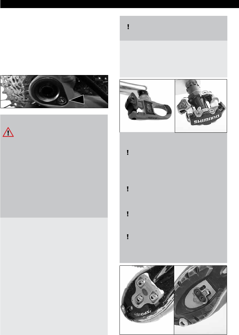
50
|
MTB/ ROAD BIKE/ TREKKINGMTB/ ROAD BIKE/ TREKKING
In unpredictable trac situations and on
dicult terrain, it is often necessary to
"click out" with one or even both shoes.
•
Practise this with both feet alternately.
•
When pedalling, place your shoe centrally
on the pedal so that you don‘t click in.
If need be, you can then support yourself
with one or both legs on the ground.
With click-in pedals, the shoe and pedal
are rmly connected in a vertical direc-
tion. When pedalling, you can not only
push the pedal down but also pull it
upwards.
To be able to use a click-in pedal to the
full, you need shoes specially designed
for the pedal system concerned and to
which the pedal hooks supplied with the
pedal can be axed.
The following description is intended
purely as an example.
Please refer to the instructions for your
pedal/shoe combination provided by the
manufacturer and/or consult your speci-
alist dealer in order to ensure that your
click-in pedal system is correctly assem-
bled and you use it correctly.
8.9 Using click-in pedals (optional)
Risk of Personal Injury and Material
Damage!
Click-in pedals are not safety pedals.
If an excessive release force is set, it is
possible that you will not be able to get
your shoes out of the pedal quick enough
in an emergency situation.
If too soft a release force is set, the shoe
may possibly become disengaged from
the pedal unintentionally when you are
riding.
In either case, there is an increased dan-
ger of falling and injury.
•
Familiarise yourself with the click-in pedals
and how to use them.
•
Practise mounting onto and dismounting
from the pedals when not moving.
Sit on the saddle and hold onto a stable
object with one hand.
Click both shoes alternately in and out.
Please consult your dealer.
•
Familiarise yourself with the release on
careful practice rides.
•
Discover for yourself the optimum tightness
setting.
•
Practise mounting and dismounting at
various release settings.
•
You can nd details on how to adjust the
release setting in the accompanying parts
instructions and/or consult your dealer.
Road Bike MTB
Road Bike MTB
8.8.7 Fork end
Please ensure that the locking screw on
the fork ends dropout of the frame (MTB
+ ROAD + TOUR + URBAN) and the fork
(ROAD + TOUR + URBAN) is tightened
correctly. The screw is only used to x the
threaded insert in place when the wheel-
set is removed, and therefore only needs
to be fastened “hand-tight”.

|
51
MTB/ ROAD BIKE/ TREKKINGMTB/ ROAD BIKE/ TREKKING
1. Have this tting work done by your
dealer.
2. To position your foot correctly on the
pedal:
a) Bring the pedal down to its lowest
position.
b) With the toe of your shoe pointing
downwards, position the hook nose of the
shoe in the front pedal insertion point.
c) When the hook nose is positioned
correctly in the pedal, push the whole
surface of the foot sharply downwards
until the clamping mechanism clearly and
audibly engages.
• The shoe is now rmly vertically connected
with the pedal.
• Depending on the pedal system, the shoe
has sideward freedom of movement.
3. To loosen your shoe from the pedal:
• Twist your heel sharply away from the bike.

52
|
MTB/ ROAD BIKE/ TREKKINGMTB/ ROAD BIKE/ TREKKING
8.10 Loading the carrier
Risk of Personal Injury and Material
Damage!
A carrier is not intended for transportati-
on of bulky items or persons.
Misuse of the carrier can lead to dange-
rous riding conditions, falls, accidents
and material damage.
Only carry compact items of luggage with
a maximum total weight of 25 kg and use
a suitable restraint system. Consider max.
weight information on carrier!
•
Place your items of luggage in the middle of
your carrier.
•
If using panniers, please also ensure that
these are suitable for your carrier.
Fit them in accordance with this Owner‘s
manual.
Please observe the relevant Instructions for
use and/or consult your dealer.
•
Attach your luggage item using a tension
clip or specially suited elasticated bungee
cords.
•
"Shake" your bike to and fro after loading it.
•
The luggage or your panniers or parts the-
reof must not work loose.
•
Your luggage or your panniers or parts
thereof must not hinder your freedom of
movement when riding.
•
Neither your luggage nor your panniers nor
parts thereof must touch the wheels.
•
Neither your luggage nor your panniers
nor parts thereof must cover your lights or
reectors.
9 During riding
(Troubleshooting)
Risk of Personal Injury and Material
Damage!
If you carry out maintenance procedu-
res you are not authorised to perform,
this may result in dangerous riding
conditions, falls, accidents and material
damage.
Have all problems not listed in the table
below checked immediately by your
dealer and if necessary rectied.
Risk of Personal Injury and Material
Damage!
If you notice any unusual handling, un-
usual noises or faults not listed in this
Chapter, this can result in dangerous
riding conditions, falls, accidents and
material damage.
•
Have anything you notice which is not listed
in the following table checked immediately
by your dealer and if necessary rectied.
•
If the measures listed herein do not provide
a remedy, please consult your specialist
dealer immediately.

|
53
MTB/ ROAD BIKE/ TREKKINGMTB/ ROAD BIKE/ TREKKING
Chain o Incorrect shift operation (see
Chapter 8.6)
Gear out of adjustment or
damaged
Possible under unfavourable
conditions
Stop,
lift the chain by hand onto the next sprocket,
lift the rear wheel,
operate the crank in the direction of drive (only if
possible with ease).
If repair is not possible in this way contact a speci-
alist workshop immediately.
Chain comes o after or
during shifting
Incorrect shift operation
(see Chapter 8.6)
Gear out of adjustment or
damaged
Possible under unfavourable
conditions
Stop,
operate the shift lever in the opposite direction,
lift the chain by hand onto the next sprocket,
lift the rear wheel,
operate the crank in the direction of drive (only if
possible with ease).
If repair is not possible in this way, contact a speci-
alist workshop immediately.
Chain jumps o perma-
nently.
Permanent incorrect operation
of gear shift
Gear out of adjustment or
damaged.
Only operate the gear shift as per instructions in
Chapter 8.6
If operation is correct, contact a specialist work-
shop immediately.
9.1 Gears and drive train
Problem Possible causes Corrective action
Gear does not shift or
not cleanly
Shift lever not operated
correctly
Operate again
Gear out of adjustment Adjust in specialist workshop
On steep incline, too great a
pressure on the pedal and/or
pedalling too slowly
Repeat gear shift on at terrain;
Shift when static: Lift rear wheel, turn crank
in direction of travel until the required gear is
engaged.
Drive train blocked after
or during shifting
Chain jammed Stop, operate gear shift in reverse, lift rear wheel
and turn crank against direction of drive.
If crank cannot be moved, under no circumstances
use force. Contact a specialist workshop immedi-
ately.
Unusual noises such
as clicking or cracking
noises, loud grinding
and/or knocking
Damaged drive train/gear
components.
Contact a specialist workshop immediately.
Uneven resistance when
pedalling
Damaged drive train/gear
components.
Contact a specialist workshop immediately.

54
|
MTB/ ROAD BIKE/ TREKKINGMTB/ ROAD BIKE/ TREKKING
9.2 Brake
Risk of Personal Injury and
Material Damage!
The brakes on your bike are amongst the most important parts when it comes to your safety.
Incorrectly functioning brakes can lead to dangerous riding conditions, falling, accidents and
material damage.
•
At the slightest problem and if the braking eect deteriorates, contact your dealer immediately.
•
Only ride the bike again after it has been properly readjusted by the dealer.
Problem Possible causes Corrective action
Brakes do not function Brake not correctly assembled Correct assembly as per Chapter 11.1
Brake damaged Contact a specialist workshop imme-
diately.
Reduced braking eect, brake
levers have to be pulled too far.
Worn brake blocks or brake pads Have brake blocks or brake pads
replaced immediately in a specialist
workshop.
Brake cable stretched, worn or
clamp/s damaged
Contact a specialist workshop imme-
diately.
On hydraulic brakes, brake system
leaking
Contact a specialist workshop imme-
diately.
9.3 Frame and suspension
Risk of Personal Injury and
Material Damage!
Frame and suspension faults may lead to dangerous riding conditions, falling, accidents and mate-
rial damage.
•
At the slightest malfunction, contact your dealer immediately.
•
Only ride the bike again after it has been properly readjusted by the dealer.
Problem Possible causes Corrective action
Noises: Creaking, knocking,
grinding or other.
Frame and/or suspension
damaged
Contact a specialist workshop
immediately.
The seat post slips into the frame
or twists out of position.
Tightening torque too low Check and correct the tightening
torque (see chapter 3.3).
In the case of frames and/or seat
posts
made of carbon
Contact a specialist workshop imme-
diately.

|
55
MTB/ ROAD BIKE/ TREKKINGMTB/ ROAD BIKE/ TREKKING
Problem Possible causes Corrective action
The seat post slips into
the frame or twists out of
position.
Incorrect assembly
The diameter of the seatpost is
too small
Dismantle and assemble correctly according
to point 11.2
Assemble a seatpost with the correct
diameter
Poor suspension response Suspension has been set
incorrectly
Adjustment according to the accompanying
parts manual
Poor suspension response
despite being adjusted
correctly
Suspension
damaged
Contact a specialist workshop immediately.
Problem Possible causes Corrective action
Noises: Creaking, knocking,
grinding or other.
Splash guard or carrier parts loose Contact a specialist workshop immediately.
Lighting system partly or
totally dysfunctional
Lighting elements (bulbs, LEDS)
burnt out
Replace lighting elements. Please consult
your dealer.
Wiring damaged Contact a specialist workshop immediately.
Dynamo defective
9.4 Splash guard, carrier and lighting system
Risk of Personal Injury and
Material Damage!
Splash guard, carrier and lighting system faults may lead to dangerous riding conditions, falling,
accidents and material damage.
•
At the slightest malfunction, contact your dealer immediately.
•
Only ride the bike again after it has been properly readjusted by the dealer.

56
|
MTB/ ROAD BIKE/ TREKKINGMTB/ ROAD BIKE/ TREKKING
9.5 Road wheels and tyres
Risk of Personal Injury and
Material Damage!
Damage to road wheels and tyres may lead to dangerous riding situations, falling, accidents and
material damage.
•
At the slightest malfunction, contact your dealer immediately.
•
Only ride the bike again after it has been properly readjusted by the dealer.
Problem Possible causes Corrective action
Road wheels "hopping" up and
down
Tyre damage
Defective spokes
Contact a specialist workshop immediately.
Noises: Creaking, knocking,
grinding or other.
Debris caught in wheel Remove debris. Afterwards ride your bike
with particular care.
Have your bike checked by a specialist work-
shop for any consequential damage.
Damage to road wheel Contact a specialist workshop immediately.
Spongy handling Air pressure too low Increase air pressure (see Chapter 7.1.3). If
the same handling occurs again shortly after
there is a slow puncture (see next line)
Increasingly spongy handling
Very unusual rolling characteris-
tics (you can feel every stone)
Flat tyre Replace tube and if necessary tyre and tape
on tubeless systems
Replacing tyres
Contact a specialist workshop
(*) immediately. The bike must not be used
until then.
(*): Changing the tube, tyre and rim tape
can only be undertaken given the required
experience.
Have your dealer demonstrate this procedu-
re to you and practise this job until you are
familiar with it.
For removing and retting road wheels, see
Chapters 8.8 and 11.1.

|
57
MTB/ ROAD BIKE/ TREKKINGMTB/ ROAD BIKE/ TREKKING
10 After falls or accidents
Risk of Personal Injury and
Material Damage!
Damage after a fall or accident may lead
to dangerous riding situations, falling,
accidents and material damage.
•
After a fall or accident, contact your dealer
immediately.
•
Only ride the bike again after it has been
properly readjusted by the dealer.
After a fall basically you must renew all damaged
bike components such as
• Handlebars
• Triathlon / time trial attachment
• Bar ends
• Handlebar stem
• Seat post (if made of carbon)
• Saddle (if saddle framework is made of
carbon)
• Rims (if made of carbon)
• Crank.
All other bike parts must be checked by your dealer
and, if necessary, replaced.
Risk of Personal Injury and
Material Damage!
More and more bikes are tted with car-
bon bre components
Carbon bre components are very sensi-
tive and if incorrectly tted and if slightly
damaged can lead to dangerous riding
situations, falling, accidents and material
damage.
•
Please note all instructions regarding assem-
bly, care, maintenance and checking these
parts in accordance with the accompanying
parts instructions.
•
Only have assembly work done on or of
carbon bre parts carried out in a specialist
workshop.
•
After damage and falls. you must consult
your dealer.
•
Only use your bike again after he has repla-
ced the damaged parts or assured you that
you can continue to use the bike without
any worries.
•
Please also refer to the information provided
in chapter 4.8
11 Transporting your bike
Risk of Personal Injury and
Material Damage!
An unsuitable transportation system
may damage parts of your bike which are
important for safety and lead to dange-
rous riding situations, falls, accidents and
material damage.
•
Only transport this bicycle inside your car.
•
Objects or items may not be placed on this
bicycle or its frame.
•
Any bike carrier (e.g. roof, rear end) that
requires the frame or bicycle to be mounted
or clamped is not suitable for this bicycle.
This bike may only be transported inside a vehicle.
Please note during transportation that the bike is
secured and is not damaged by other packaging
items, for example.
For transportation you may remove the front and
rear wheels and the saddle stem with saddle if these
are tted with quick releases. Only undertake this
disassembly if you are sure that you can reassemble
these parts correctly.
See Chapters 8.3, 8.8
If your road wheels are bolted to the frame (e.g. in
the case of hub gears), consult your dealer
Danger of material damage!
If your bike is inside a vehicle, solar radia-
tion can cause the tyres to burst or come
away from the rim.
•
Let the air out of the tyres prior to transpor-
tation and ll them again after transportati-
on (see Chapter 7.1.3)

58
|
MTB/ ROAD BIKE/ TREKKINGMTB/ ROAD BIKE/ TREKKING
11.1 Fit and remove road wheels
Risk of Personal Injury and
Material Damage!
Incorrectly tted road wheels can lead to
dangerous riding situations, falling, acci-
dents and material damage.
•
You must have your dealer demonstrate
tting and removing your road wheels.
•
Practise this job at least once under his
supervision and control.
•
Only remove and t the seat post and saddle
if you are sure you have mastered this job.
Risk of burns!
After long descents, the bicycle rims and
brake disks can get very hot.
•
Do not touch the rims or brake disks imme-
diately after a descent.
•
Let the rims and brake disks cool down
before you touch them.
•
In order to check the temperature, touch the
rims and brake disks very briey with your
nger. If they are hot, wait a few minutes
and repeat the test until the rims and brake
disks have cooled down.
Danger of material damage!
•
Hydraulic brakes must under no circumstan-
ces be operated after removing the road
wheel!
•
If your bike has a disk brake, use the man-
datory transportation wedges supplied for
that purpose for transportation following
removal of the road wheel.
•
Remove these immediately prior to retting
the road wheels.
Please comply with the accompanying parts
instructions here.
Risk of Personal Injury and
Material Damage!
Rim brakes only:
when tting and removing, the brake
blocks can get twisted.
•
When tting the road wheels, please note
that the brake blocks are correctly positi-
oned (see Chapter 7.8).
•
If these are not correctly positioned, please
contact a specialist workshop.
For transportation you may remove and
later replace the road wheels on your bike
if these are tted with quick releases.
If your bike has rim brakes please be
careful that you do not change the po-
sition of the brake blocks with the tyre.
This could happen especially in the case
of large-volume tyres. If the tyre does
not pass easily between the brake caliper
blocks, let a sucient amount of air out
of them.
Then inate the tyres afterwards to the
correct pressure.
11.1.1 All categories/series except the
category racing bike/triathlon
1. Remove the front wheel rst
(continue with 3).
2. Switch to the smallest pinion of the rear
wheel’s sprocket cassette (see chapter
8.6).

|
59
MTB/ ROAD BIKE/ TREKKINGMTB/ ROAD BIKE/ TREKKING
Risk of Personal Injury and
Material Damage!
Spinning road wheels can cause injuries
to your hands.
•
Never put your hand near a spinning road
wheel.
•
Come to a complete standstill before carry-
ing out works on, or around, the wheels.
•
In order to do this, lift the rear of the bicycle
up, actuate the corresponding shift lever
and turn the crank by hand in the riding
direction until the chain is placed on the
smallest pinion.
•
Brake the road wheel until it comes to a
complete standstill (see chapter 8.7).
3. Open the brake (only applies to rim bra-
kes, not to disk brakes)
a) As for rim brakes with cable control
(e.g. from Shimano):
•
Press the brake shoes together with one
hand and remove the cable guide from the
yoke.
b) On Magura: hydraulic rim brakes:
•
Move the xing lever over and remove the
entire brake assembly including brake boos-
ter from the brake sockets.
•
Please make sure you do not lose any dis-
tance washers that may come loose.
4. On front wheel with hub dynamo (if
tted):
•
Remove the push-t connector between the
dynamo and cable.
5. Loosen the wheel hubs.
•
Open the quick release on your road wheel
(see also Chapter 8.8 Quick Releases)
•
Raise the rear of the bike, operate the shift
lever concerned and turn the crank in the
drive direction until the chain lies correctly
on the smallest sprocket.
•
Turn the locknut enough to allow sucient
room on the axle.
With other types of clamping.
•
Loosen the clamp as per the accompanying
parts instructions
6. Remove the road wheels from the frame
and forks.
•
Front wheel: Lift the bike up by the handle-
bars and withdraw the road wheel from the
front fork dropouts.
•
Rear wheel: lift the bike up slightly at
the back and press the gear mechanism
backwards. In this position, push the rear
wheel gently in the direction of the dropout
openings.

60
|
MTB/ ROAD BIKE/ TREKKINGMTB/ ROAD BIKE/ TREKKING
7. After removing, place the bike carefully
on its left hand side.
Danger of material damage!
With no rear wheel, the frame and/or the
gear mechanism can become damaged.
•
After removing the rear wheel lie the bike on
its left side or use a suitable assembly stand.
To t your road wheels. Fit the rear wheel
rst.
1. a) Inserting the rear wheel
•
Lift up the rear of the bike,
placing the rear wheel under it so that the
chain is over the smallest sprocket.
•
Disk brakes: insert the road wheel so that
the brake disk can be easily pushed between
the brake pads.
•
Carefully lower the rear of the bike until the
axle is at the dropout stop on the right and
left sides.

|
61
MTB/ ROAD BIKE/ TREKKINGMTB/ ROAD BIKE/ TREKKING
1. b) Inserting the front wheel:
•
Lift up the bike by the handlebars.
•
Place the front wheel under the front forks
dropouts
•
For disc brakes: Attach the wheel in such a
way that the disc brakes are able to move
freely between the brake pads.
•
Carefully lower the forks until the axle is
ush at the dropout stops on the right and
left sides.
2. Tighten the wheel hubs.
•
When tightening with quick releases: see
Chapter 8.8.
•
With other types of clamping: tighten
the hubs as per the accompanying parts
instructions.
3. a) Close rim brakes
on cable brakes:
•
Press the brake shoes together.
•
Insert the cable in the yoke.
3. b) Hydraulic rim brakes: tting is as remo-
val only in reverse sequence.
•
Place the brake booster on the lead screws
•
Insert any distance washers in the correct
position and place the brake on the brake
bosses.
•
Swivel the locking lever so that the brake is
xed in place again.
4. Please ensure that the brake blocks
correctly cover the rim shoulder when
operated.

62
|
MTB/ ROAD BIKE/ TREKKINGMTB/ ROAD BIKE/ TREKKING
11.1.2 Race/Triathlon
1. Remove the front wheel rst (continue
with 3.)
2.
Switch to the smallest pinion of the rear
wheel’s sprocket cassette (see chapter 8.6)
Risk of Personal Injury and
Material Damage!
Spinning road wheels can injure your
hands.
•
Never put your hand near a spinning road
wheel.
•
Brake the spinning road wheel by using the
corresponding brake lever until it comes to
a complete standstill before performing any
work near the road wheel.
•
In order to do this, lift the bicycle rear up,
actuate the corresponding shift lever and
turn the crank by hand in the riding direc-
tion until the chain is placed on the smallest
pinion.
•
Brake the road wheel until it comes to a
complete standstill (see chapter 8.7).
3. Open rim brake.
5. On front wheel with hub dynamo (if tted):
•
Ret the push connector between the hub
dynamo and the cable.
6. Check installation:
•
Operate the brakes.
•
If the brake block or brake touches the rim
or the brake disks, this can indicate incorrect
seating of the hub in the dropouts.
•
In that case release the quick release, check
and correct the hub seat and close the quick
release again.
•
The brake (on rim brakes) must not be
opened during this procedure. If there is no
improvement after this, please contact your
dealer immediately.
•
Check that the lighting (if tted) is working.
•
Ensure that the road wheels do not come
into contact with either mudguards or
carrier (if tted).

|
63
MTB/ ROAD BIKE/ TREKKINGMTB/ ROAD BIKE/ TREKKING
•
a) On racing bike brakes:
Shimano und Sram:
•
Move the lever upwards.
•
•
b) Campagnolo:
There is no lever on the brake:
to release press the pin on the brake lever
from inwards to outwards.
At the same time pull on the brake lever
slightly.
4. Loosen the wheel hubs.
•
•
Open the quick release on your road wheel
(see also Chapter 8.8 Quick Releases)
Turn the locknut enough to allow suci-
ent room on the axle. With other types of
clamping.
5. Remove the road wheels from the frame
and forks.
•
•
Front wheel: Lift the bike up by the handle-
bars and withdraw the road wheel from the
front fork dropouts.
Rear wheel: Lift the bike up slightly at
the back and press the gear mechanism
backwards. In this position push the rear
wheel gently in the direction of the dropout
openings.
6. After removing, place the bike carefully
on its left-hand side.
Danger of material damage!
With no rear wheel, the frame and/or the
gear mechanism can become damaged.
•
After removing the rear wheel, lie the bike
on its left side or use a suitable assembly
stand.
To t your road wheels.
Fit the rear wheel rst.
1. a) Inserting the rear wheel
•
Lift up the rear of the bike.

64
|
MTB/ ROAD BIKE/ TREKKINGMTB/ ROAD BIKE/ TREKKING
•
placing the rear wheel under it so that the
chain is over the smallest sprocket
•
Carefully lower the rear of the bike until the
axle is at the dropout stop on the right and
left sides.
b) To assemble the front wheel
•
Lift up the bike by the handlebars,
•
placing the front wheel under the front forks
dropouts and
•
carefully lower the forks until the axle is ush
at the dropout stops on the right and left
sides.
2. Tighten the wheel hubs.
•
When tightening with quick releases: see
Chapter 8.8
3. Close rim brakes
a) On racing bike brakes:
Shimano und Sram:
•
Move the lever downwards.
b) Campagnolo:

|
65
MTB/ ROAD BIKE/ TREKKINGMTB/ ROAD BIKE/ TREKKING
•
There is no lever on the brake:
•
Follow the reverse procedure to opening
and press the pin on the brake lever from
outwards to inwards.
•
At the same time, pull the brake lever.
4. Check installation:
•
Operate the brakes.
•
If the brake block or brake touches the rim
or the brake disks, this can indicate that the
hub has not been correctly seated in the
dropouts.
•
In that case release the quick release, check
and correct the hub seat and close the quick
release again.
•
The brake (on rim brakes) must not be
opened during this procedure. If there is no
improvement after this, please contact your
dealer immediately.
11.2 Remove and replace seat post
and saddle
Risk of Personal Injury and
Material Damage!
An incorrectly tted seat post can lead to
dangerous riding situations, falling, acci-
dents and material damage.
•
You must have your dealer demonstrate
tting and removing your seat post.
•
Practise this job at least once under his
supervision and control.
•
Only remove and t the seat post and saddle
if you are sure you have mastered this job.
For transportation, you can remove your bike‘s seat
post complete with saddle and replace it again
afterwards.
The seat post is held with a clamp in the frame seat
tube and is tightened with either a quick release or a
hexagon socket.
On carbon bre seat posts, special types may be
tted with two screws.
For clamping without a quick release, a hexagon
socket and a torque wrench of the appropriate size
are required. Please also consult your dealer.
To remove your seat post:
1. Release the saddle clamp at the quick
release as per Chapter 8.8 or by loosening
the Allen screw with an Allen key.
2. Withdraw the saddle with seat post from
the frame.
To replace your seat post:

66
|
MTB/ ROAD BIKE/ TREKKINGMTB/ ROAD BIKE/ TREKKING
1. On carbon seat post and/or saddle
•
Apply assembly paste to the seat post and
to the inside of the seat tube and only use
assembly paste for carbon parts for this
procedure.
•
Seat post and seat tube must not be gre-
ased. Only carbon assembly paste may be
used.
•
Seat posts made of aluminium may only be
tted using a carbon assembly paste.
2. Push the saddle with seat post into the
seat tube until the desired saddle height
is obtained. In this position the lower end
of the seat post (length (x)) must be at
least (y) mm below the top edge of the
seat tube (see denition below).
Do not rely on the marking on the seat
post.
To check the correct insertion distance (y):
hold a nger tip against the seat post
when tted directly above the clamp.
Keep your nger tip in this position and
withdraw the seat post from the seat
tube.
Hold the seat post laterally beside the
seat tube so that your nger is again level
and directly above the clamp.
In this position the lower end of the seat
post (length (x)) must be at least (y) mm
below the top edge of the seat tube.
120mm (y) at 400mm (x)
120mm (y) at 420mm (x) RockShox Reverb
110mm (y) at 380mm (x)
100mm (y) at 350mm (x)
3. Turn the saddle so that the saddle points
in the direction of travel.
4. Ensure that the clamp is ush in the frame
and that the seat tube slots and the clamp
are covered.
5. Close the quick release as per chapter 8.8
or tighten the allen screw with a torque
wrench.
Please observe assembly instructions and
the specied torque in the accompanying
parts instructions indicated in table 3.3.
Risk of Personal Injury and
Material Damage!
An over-tightened carbon bre seat post
can break when riding and lead to dange-
rous riding situations, falling, accidents
and material damage.
•
The seat tube clamp must be tightened
rmly in order to prevent the seat post from
lowering into the frame or laterally twisting
during the ride.
•
If the seat post does not remain in the desi-
red position, even though you have reached
the maximum admissible tightening torque,
please consult your specialist dealer imme-
diately.
Please observe assembly instructions and
the specied torque in the accompanying
parts instructions

|
67
MTB/ ROAD BIKE/ TREKKINGMTB/ ROAD BIKE/ TREKKING
12 Cleaning and caring for your
bike
Risk of Personal Injury and
Material Damage!
Corrosion can damage components of
your bike which are important for safety
so that they are no longer secure. These
components may then brake during ri-
ding and thus result in serious falls.
Corrosion is caused, amongst other
things, by
-
salt (e.g. due to salt spreading in winter)
-
salty air (e.g in coastal or industrial areas)
-
perspiration.
Danger of material damage!
Do not use steam washers. The high pres-
sure water jet can damage your bike.
Good maintenance will increase the life of your bike
and its components. Clean and maintain your bike
regularly.
For wet cleaning, use a gentle water jet or a bucket
of water and a sponge.
Only use clean fresh water or desalinated water.
There are many ways of washing a bike. A proven
cleaning recommendation for a very dirty bike is as
follows:
1. With a gentle water jet, remove large
items of debris such as soil, stones and
sand etc.
2. Let the bike dry o to a certain extent.
3. Spray your entire bike with a suitable
detergent.
With many detergents and if there is only
a low level of soiling, simply spraying and
rinsing o after the specied time for
them to work is sucient.
You can remove stubborn dirt after the
working time, for example, with a radia-
tor paintbrush before rinsing o.
Danger of material damage!
Cleaning, lubrication and preserving
agents are chemical products.
Incorrect use can damage your bike.
•
Only use products expressly suitable for
bikes.
•
Ensure that these products do not attack
either paint, rubber, plastic or metal parts
etc. Consult your dealer.
•
Follow the respective manufacturer‘s inst-
ructions.
4. Rinse the entire bike with a gentle water
jet and allow it to dry.
5. Clean the chain.
•
Drip a suitable chain cleaner into a clean,
spirit-free cotton cloth and wipe the chain
down. When doing so, slowly operate the
crank against the direction of drive.
•
Repeat this process as often as possible with
a clean area of the cloth until the chain is
clean.
•
Drip a suitable chain cleaner into a clean,
spirit-free cotton cloth and wipe the chain
down.
If cleaner remains between the chain
links, the new grease will be immediately
broken down and will be totally ineec-
tive.
•
Sparingly apply a lubricant suitable for
bicycle chains to the chain links.
Danger of material damage!
Greases for motor cycle chains will gum
up your bike chain and the drive chain
components.
•
Only use lubricants expressly approved for
use with bike chains.

68
|
MTB/ ROAD BIKE/ TREKKINGMTB/ ROAD BIKE/ TREKKING
Clean and lubricate your chain as descri-
bed after every ride in wet conditions and
every extended ride on a sandy subsur-
face and at the latest every 200 km.
Risk of Personal Injury and
Material Damage!
If too much lubricant is used it can drip
onto the rim and brake disk and contami-
nate them.
This will reduce the eectiveness of the
brakes
•
Remove excessive lubricant on the chain
using a clean, dry and spirit-free cotton
cloth.
•
Clean the rim and brake disk with a suita-
ble degreasing agent. Please consult your
dealer.
Risk of Personal Injury and
Material Damage!
If wax polish spray or a preserving agent
gets onto the rim or brake disks and/
or brake blocks, the eectiveness of the
brakes will be reduced.
•
Clean these parts with a suitable degreasing
agent. Consult your specialist dealer.
6. Clean any remaining very dirty parts by
hand using a clean spirit-free cotton cloth
using a suitable detergent.
7. Spray the entire bike with a suitable wax
polish or similar preserving agent.
Exceptions:
• Brake blocks or brake pads
• Rims in the case of rim brakes
• Brake disks
• Handlebar grips/ brake lever/ shifter
• Saddle
• Tyre
8. Polish your bike after the prescribed
working time using a clean, spirit-free
cotton cloth.
9. Clean the brake blocks, brake pads, rims
(in the case of rim brakes) and brake disks
by hand using a clean, spirit-free cloth
using a suitable degreasing agent.
Risk of Personal Injury and
Material Damage!
Worn parts and unrepaired damage can
lead to dangerous riding situations, falls,
injuries and property damage.
•
Regularly maintain and service your bicycle.
•
Take your bicycle to a specialist workshop at
the compulsory maintenance intervals.
•
Only this way, worn parts and possible
damages can be discovered and repaired.
Risk of Personal Injury and
Material Damage!
Compared to adults, children and juveni-
les often use their bicycles in a way that
damages the material and parts more
quickly.
•
Take bicycles of children and juveniles which
are frequently used to a specialist workshop
for inspection every 6 months.
•
If you discover damage on a bicycle ridden
by children or juveniles, immediately take it
to a specialist workshop for inspection.

|
69
MTB/ ROAD BIKE/ TREKKINGMTB/ ROAD BIKE/ TREKKING
Servicing schedule:
Have servicing carried out at the intervals prescribed only in a specialist workshop authorised by
the manufacturer.
Type of inspection Normal use Frequent sport, competition or use of
a competitive nature
1. Inspection at the latest after 200 km or 2
months
at the latest after 100 km or 1 month
Subsequent inspections every 2000 km or 1 x per annum every 500 km or every 2 months
Check brake pads/brake
blocks
every 400 km every 100 km
Check brake disks every 400 km every 100 km
Check chain wear every 500 km every 250 km
Check the rear suspension
bearing for full-suspension
frames incl. checks/relubrica-
ting the roller bearing on the
shock absorber (if applicable)
Every 500 km or once a year Every 250 km or every two months
Replace handlebars and stem after a crash (see Chapter 10)
as indicated by component manu-
facturer or every 5 years at the latest
after a crash (see Chapter 10)
as indicated by component manufactu-
rer or every 2 years at the latest
Under unfavourable conditions, your chain can wear rapidly. Changing it early will extend
the life of your sprockets.
13 Storing your bike for
a lengthy period
Danger of material damage!
Incorrect storage of a bike can damage
bearings and tyres and promote corro-
sion.
•
Please observe the following instructions.
1. Clean and maintain your bike as descri-
bed in Chapter 12.
2. Only store your bike in dry and dust-free
premises.
3. Use suitable bike stands (e.g. tripod, wall
hooks). Please consult your dealer.
4. Place your bike with one or both wheels
on the oor
•
Lift your bike every 2-3 weeks and spin your
wheels a couple of turns.
•
Rotate the handlebars back and forwards a
couple of times.
•
Turn the crank by hand a couple of revolu-
tions against the direction of drive.
•
When using again, carry out a check as
described in Chapter 7.

70
|
MTB/ ROAD BIKE/ TREKKINGMTB/ ROAD BIKE/ TREKKING
14 Warranty and Guarantee
14.1 Warranty
Generally, we grant the two years by law
warranty for all Cube frames and rigid forks.
The period of validity counts from the day of
purchase.
14.2 Guarantee
We extend the legal warranty for some of
our Cube frames and rigid forks as following,
counting from the day of purchase:
Aluminium 6 years guarantee
Carbon, Alu-Carbon 3 years guarantee
In case of material failure within this period
of time, we obligate ourselves to replace the
article with the same or a corresponding
one.
We reserve the right to repair certain
damaged frames and parts or to get them
replaced by the corresponding successor.
If the frame of the same type is not available
any more, we reserve the right, to deliver a
substitute which diers in colour and design
from the original one. There is no legal claim
to obtain an article of the exact same type.
Technical alterations and changes beyond
the legal guarantee (2 years) will not be re-
funded and will be executed free of charge.
Exception:
The extended guarantee is not granted
for the models FRITZZ, HANZZ and TWO 15
including all assembly parts needed for the
frame change.
The statutory warranty of 2 years is valid for
these exceptions.
14.3 Warranty Policy
Warranty only refers to frames and rigid
forks, not to paint and decor.
The extra costs for parts needed because of
the frame changes (e.g. derailleurs, headsets,
shocks, etc.) are not covered by warranty
and have to be paid by the customer.
14.4 Warranty claim/warranty is void
Due to modications without ocial appro-
val by the CUBE dealer.
Due to expansion of any kind of electric
drive (e.g. front hub motor, rear hub motor,
middle motor, etc.).
In case of deciencies and damage:
•
by additional accessories (e.g. bags, locks,
carriers, etc).
•
due to a violation of this guideline.
•
due to force majeure, accident, abuse,
unprofessional repairs, lacking service / care
or wearing.
•
due to misuse (e.g. use of bicycle not accor-
ding to dedicated category (see 2.1.3 and
4.1); use of a double crown fork; extension of
system travel; use of larger disc brake rotors;
overload by jumps, etc).
•
due to a use of replacement parts not accor-
ding to orignial bicycle specication or by
CUBE approved spare parts.

|
71
MTB/ ROAD BIKE/ TREKKINGMTB/ ROAD BIKE/ TREKKING
After inspecting these items, please check o!
Comments:
15 Handover inspection
checklist
Purchaser signature (legal guardian for children under 18 years of age)
Place, date: Retailer signature:
Inspecting the brake
Laying of brake cables/lines
Adjustment of the hand brake lever
Adjustment of the brake pads
Visual tightness test of the hydraulic brake systems
Checking all fastening screws in the brake
system
The functioning and response of the front and
rear wheel brakes
Inspecting the gearshift:
Laying the hub cable and shift cable
Adjustment of the gear lever or gearshifter
Adjustment of the end stops (derailleur/switch-
gear)
Adjustment of the cable tension
Functioning and freedom of movement
of the gearshift
Checking all fastening screws in the
gearshift system
Inspecting the chassis:
Basic functions and tightness of the front fork
Basic functions and tightness of the suspension
strut, adjustment/freedom of movement of the
steering head bearing, checking all fastening
screws of the chassis components
Inspecting all screw connections in the chain-
stays
Inspecting the wheels:
Concentricity and centring of the wheel rims,
concentricity and position of the cover
Testing the spoke tension / air and tyre pressure
Correct installation and xed position of the
wheels
Other inspections:
Adjustment and xed position of the handlebars
and handlebar stem, xed position of the crank
arm
Adjustment and xed position of the saddle and
seatpost, xed position of the handles
Fixed position of the assembly rivet of the chain
Functioning of lights (if available)
Adjustment and xed position of the carrier,
mudguards and kickstands (if available)
Assembly and xed position of other attach-
ment parts
When handing over the bicycle:
The purchased object was handed over in a
complete and perfect condition including the
operating manual.
Verbal instructions were given on the safe use of
the bicycle, particularly operating guidelines for
the disc brakes – if applicable.
Reference was made to the respective instruc-
tions in the operating manual which are to be
observed.
Reference was made to the warranty obligations
in the CUBE operating manual.

Das Fahrrad wurde endmontiert von:
The bicycle was finally assembled by:
und wird in einem fahrbereiten Zustand übergeben.
and will be handed over n a roadworthy condition.
Stempel/ stamp
Unterschrift des Händlers/ Signature of the dealer
Datum
Date
Ort
Location
Händler / Verkäufer:
Retailer/seller:
Name Verkäufer:
Name of retailer:
Firma:
Company:
Straße:
Street:
PLZ / Ort:
Post code/city:
Land:
Country:
Telefon / Fax:
Telephone/fax:
E-Mail:
Kunde / Käufer:
Customer/purchaser
Nachname:
Name:
Vorname:
Surname:
Straße:
Street
PLZ / Ort:
Post code/city:
Telefon:
Telephone:
Das Original verbleibt in dieser Bedienungsanleitung
The Original should remain in the Owner's Manual
