
ECLYPSE™ ECY-PTU-107/207/208
Connected Terminal Unit Controller
Product Description
The ECLYPSE Connected Terminal Unit Controller (ECY-PTU) is designed to control terminal units such as fan coil units, chilled beams, ceilings, and
heat pumps.
It integrates a control, automation and connectivity server, a power supply, and dedicated I/Os in one convenient package. Each model supports BAC-
net/IP communication and is listed as a BACnet Building Controller (B-BC) and feature wired and wireless advanced IP connectivity for efficient and reli-
able installation.
The ECY-PTU comes with an embedded web server that enables web-based application configuration and an HTML5 visualization interface. It also fea-
tures embedded scheduling, alarming, and logging. Control logic and graphic user interface can be customized as required for the application.
Moreover, as part of the Smart Room Control solution, these controllers can control lighting fixtures (DALI, ON/OFF, dimming) and shades/sunblind mo-
tors (24 VDC or 100-240 VAC, up/down and angle rotation) through additional expansion modules.
General Installation Requirements
For proper installation and subsequent operation of each controller, pay special attention to the following recommendations:
£ Upon unpacking the product, inspect the contents of the carton for shipping damages.
Do not install damaged modules
.
£ Avoid areas where corroding, deteriorating, or explosive vapors, fumes or gases may be present.
£ Ensure the mounting surface can support the controller, DIN rail, and any user-supplied enclosure.
£ Allow for proper clearance around the controller’s enclosure, and wiring terminals to provide easy access for hardware configuration and mainte-
nance, and to ventilate heat generated by the controller.
£ The controller’s datasheet specifies the power consumption (amount of heat generated), the operating temperature range, and other environmental
conditions the controller is designed to operate under.
£ Ensure that all equipment is installed according to local, regional, and national regulations.
£ If the product is used and/or installed in a manner not specified by Distech Controls, the functionality and the protection provided by the product may
be impaired.
£ SELV (Separated Extra Low Voltage) inputs/outputs must be connected to other SELV equipment inputs/outputs.
£ PELV (Protective Extra Low Voltage) inputs/outputs must be connected to other PELV equipment inputs/outputs.
£ It is recommended that the controller(s) be kept at room temperature for at least 24 hours before installation to allow any condensation that may
have accumulated due to low temperature during shipping/storage to evaporate.
I n s t a l l a t i o n G u i d e
2 / 14
£ Orient the controller with the ventilation slots towards the top to permit proper heat dissipation. When installed in an enclosure, select one that pro-
vides sufficient surface area to dissipate the heat generated by the controller and by any other devices installed in the enclosure. A metal enclosure
is preferred. If necessary, provide active cooling for the enclosure.
£ Do not drop the controller or subject it to physical shock.
£ The controller must be installed in an appropriate ventilated enclosure, which minimum dimensions are 240 x 240 x 100 mm.
£ If the controller is to be mounted on a metallic support, this same metallic support is to be connected to a protective earth.
£ Equipment without terminal block covers must be wall-mounted or DIN rail-mounted inside a supplementary enclosure (rated as IP20 or better) that
can only be accessed by qualified personnel.
£ Equipment with terminal block covers can only be wall-mounted on a flat surface that is sufficiently large to provide space around the equipment. In
this installation scenario, conductors must be made inaccessible and wiring must comply with local wiring regulations and methods appropriate for
fixed equipment installation in a building (the use of trunking for example).
£ UL-compliant installation requires the product to be installed in a certified electrical safety box.
Any type of modification to any Distech Controls product will void the product’s warranty.
Operating, handling, or servicing this product should be ensured by a qualified operator. Turn off the power
before any kind of servicing.
Take reasonable precautions to prevent electrostatic discharges to the product when installing, servicing, or
operating it. Discharge any accumulated static electricity by touching a grounded object with your hand before
handling the product.
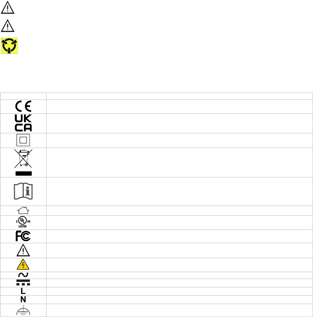
Device Markings (Symbols)
Certain markings (symbols) can be found on the controller and are defined as follows:
Symbol Description
CE marking: This device conforms to the requirements of applicable EC directives.
UKCA marking: This device conforms to the requirements of applicable Great Britain regulations.
Double Insulation
marking: These controllers are built using double insulation.
Products must be disposed of at the end of their useful life according to local regulations.
Read the Hardware Installation Guide for more information.
For indoor use only.
UL marking: This device conforms to the requirements of the UL certification.
FCC marking: This device complies with FCC rules part 15, subpart B, class B.
Warning Symbol: Significant information required. Refer to the Hardware Installation Guide.
HIGH VOLTAGE Symbol: Direct contact will cause electrical shock or burn.
Alternating Current
Direct Current
Line
Neutral
Functional Earth. (CEI 60417 n° 5018)
3 / 14
General Wiring Recommendations
Risk of Electric Shock:
Turn off power before any kind of servicing to avoid electric shock.
£ All wiring must comply with electrical wiring diagrams as well as national and local electrical codes.
£ To connect the wiring to a device, use the terminal connectors. Use a small flat screwdriver to tighten the terminal connector screws once the wires
have been inserted (strip length: 0.25’’ (6mm), maximum tightening torque 0,4 Nm (3.45 in-lb)).
£ Comply with all network and power supply guidelines outlined in the Network Guide.
£ Keep wiring separate according to their function and purpose to avoid any ambient noise transmission to other wires. Use strapping to keep these
wires separated. For example, keep power, hazardous voltage, SELV, PELV, network, and input wiring separate from each other.
£ Keep input and output wiring in conduits, trays or close to the building frame if possible.
£ Power type cables (i.e. for power, 3-wire voltage and current inputs and outputs) should be kept apart from other types of wiring to avoid any ambi-
ent noise transmission to other wires.
£ Keep all wires away from high speed data transmission cables (for example, Ethernet, etc.).
£ Conductors must be made inaccessible and wiring must comply with local wiring regulations and methods appropriate for fixed equipment installa-
tion in a building.
£ Installation must be carried out in a fashion such that double insulation integrity is maintained.
£ The maximum number of devices on one trunk should be below 50 devices to ensure proper communication and reduce leakage current effect.
£ If all controllers are connected to the Same Main supply voltage with proper GFI, the default current will be limited by the GFI. The current leakage
value of a single controller is below < 0,5 mA rms.
£ Each controller has a leakage current at the ground of less than 0.5 mA rms. This leakage current must be taken into account when designing the
electrical installation to protect against electrical shock in the case where a shielded ethernet cable is used.
£ Always use unshielded cabling with a minimum Category 5 (CAT5) cable for ethernet communications.
£ In a case when shielded ethernet cables are used, a functional earth must be connected to the functional Earth input or COM input of each con-
troller. The functional earth connection can also be done using the ports of the switch used to ensure a return path to the ground for leakage current.
The differential protection to the earth must be adapted accordingly.
£ Do not connect the universal inputs, analog/digital outputs or common terminals to earth or chassis ground (unless stated otherwise and/or using
shielded Ethernet cable).
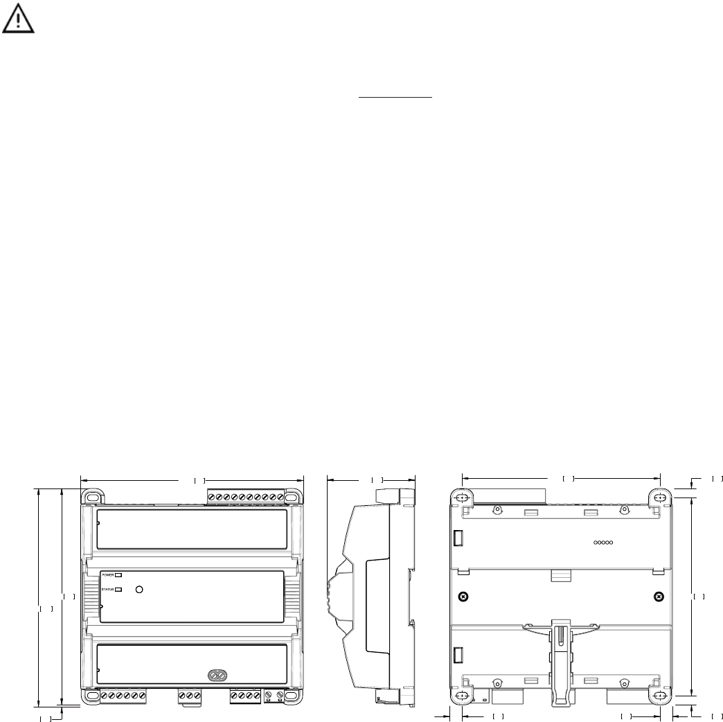
Module Enclosure Dimensions
5.71145.00
5.54
140.84
5.60142.22
Front
2.2456.88
Profile
Millimeters [Inches]
0.246.04
5.07
128.76
0.246.04
5.08129.01
0.317.990.317.99
Back
0.051.38
Figure1: Dimensions without terminal covers
4 / 14
145.00
194.85
Front
Profile
5.71
7.67
Front
2.2456.88
Profile
Millimeters [Inches]
1.30
0.31
7.99
Back
5.07128.76
1.3033.04
33.04
5.08129.01
Back
0.31
7.99
Figure2: Dimensions with terminal covers
Mounting Instructions
The controller can be mounted on a DIN rail for fast installation and easier maintenance. The controller also has four mounting holes to be mounted in a
panel or on a wall.
If the controller is to be installed out of an electrical box, it is a must to use the optional terminal block cover.
Ensure that the mounting surface can support the controller, DIN rail, and any site-supplied enclosure.
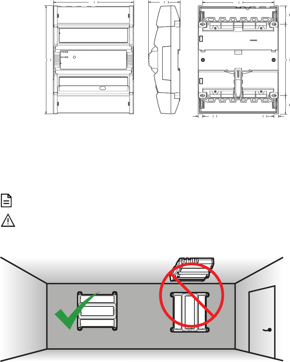
The controller must be mounted in a horizontal position as indicated in this guide to ensure proper airflow and
heat dissipation. Any other position may cause excess heat accumulation and may result in a damaged
controller.
Mounting Positions
The controller’s mounting orientation must be horizontal with controller’s back attached to a vertical wall surface.
Figure3: Permitted Mounting Position

5 / 14
DIN Rail-Mounted Installation
1. Securely mount the DIN rail horizontally on the wall.
2. Clip the controller onto the DIN rail.
Figure4: DIN-rail mounted controller
3. To detach the controller from the DIN rail, use a flat screw driver to pull down on the release clip located at the bottom center of the controller and pull
it off the DIN rail, bottom first.
Din Rail Release Clip
Figure5: Typical DIN Rail-Mounting Release Clip
Wall-Mounted Installation
Figure6: Mounting hole positions
1. Use the mounting holes to mark the location of any holes that need to be drilled.
2. Drill the holes.
3. Clean the surface
4. Mount the module using a No. 8 slotted hex, size: 1/4" or equivalent mounting hardware appropriate to the wall material type.
Figure7: Appropriate Mounting Hardware (Field Supplied)

6 / 14
Power Wiring
Overvoltage Category II - 2.5 kV
Voltage 100-240 VAC; ±10%
Maximum Consumption 4 A
For terminal block connector wiring best practices, see General Wiring Recommendations.
Always conform to the wiring regulations in effect in your jurisdiction.
The power supply must be connected to the mains using the provided detachable connector.
The power wires must be between 18 AWG (1 mm²) and 16 AWG (1.5 mm²). Use wire with appropriate insulation
for this application.
Operating, handling, or servicing this product must be performed by trained personnel only. Turn off power
before any kind of servicing.
Risk of electric shock. Do not open. This product has no user-serviceable parts inside. When power has been
disconnected, dangerous residual internal voltages may still be present. Return this unit to Distech Controls for
maintenance or repair.
AC Power
Source (Mains)
Circuit
Breaker
Neutral
Line
Figure8: Power Wiring
7 / 14
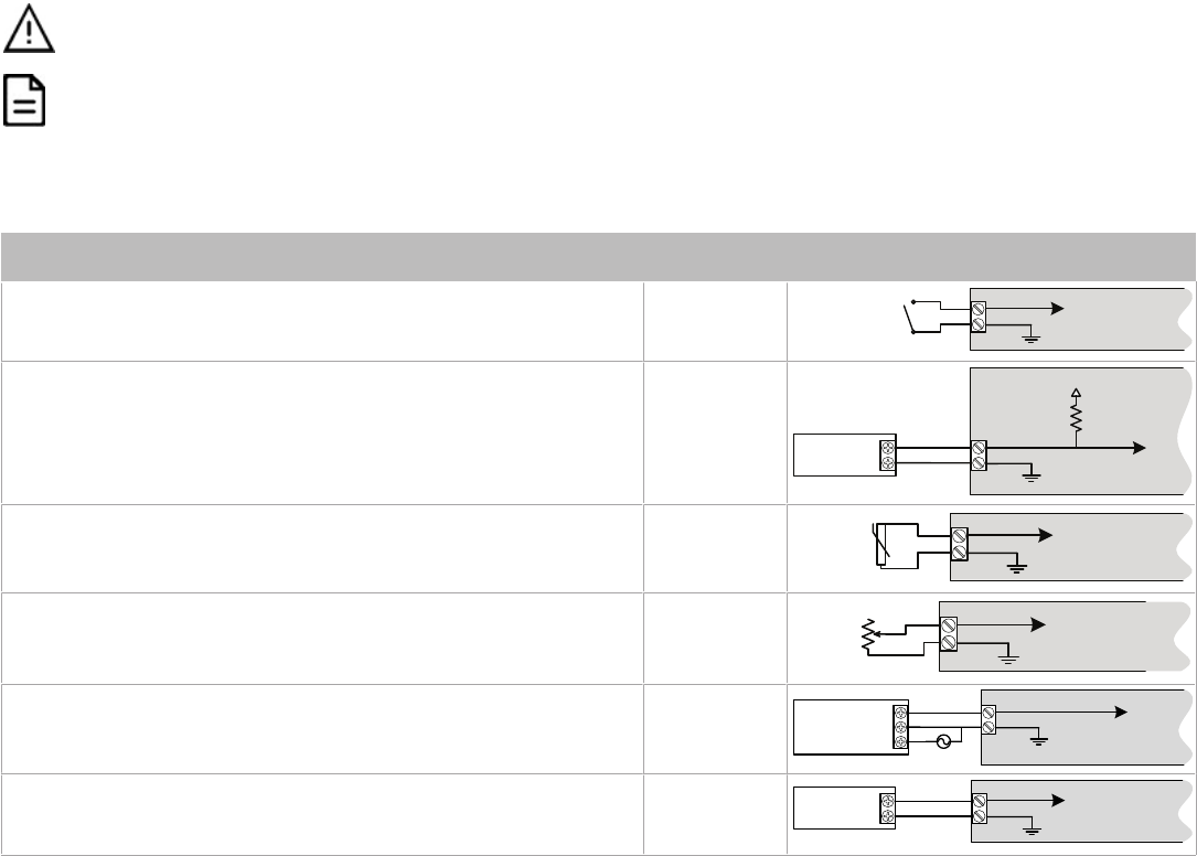
Input Wiring
Input options must be properly configured in EC-
gfx
Program to ensure correct input readings. For terminal block connector wiring best practices, see
General Wiring Recommendations. Inputs can be connected as follows.
Before connecting a sensor to the controller, refer to the installation guide of the equipment manufacturer.
£ For a wire length less than 10’ (3m), either a shielded or unshielded 18AWG wire may be used.
£ For a wire up to 33’ (10m) long, a shielded 18AWG wire is recommended.
£ The shield of the wire should be grounded on the controller side only and the shield connection to the
ground should be kept as short as possible.
£ If functional Earth is connected, input circuits will be PELV.
£ If functional Earth is NOT connected, input circuits will be SELV.
Sensor Input Type Input Designa-
tion
Input Connection Diagram
£ Dry Contact input.
£ Pulsed input.
£ UIx
£ DIx
£ SIx
UIx, DIx or SIx
COM
To Digital Input
Digital Dry Contact
NO-NC
£ Pulse input used with a 2-wire sensor powered by its own power source.
£ This input supports a maximum input frequency of 100Hz (5ms minimum
ON/OFF) for DIx, or 1Hz (500ms minimum ON/OFF) for UIx and SIx.
£ Connect the pulse input according to the figure for a pulse meter that can
pull-down a +3.3VDC supply with a 1kΩ (for DIx) or 10kΩ (for UIx and SIx)
pull-up resistor (Internal supply type).
£ DIx
£ UIx
£ SIx
Pulse Meter
Output
C
ontroller
P
ulse
Inpu
t
E
quivalent
Circuit
UIx or DIx
COM
To Pulse Count
Accumulator
+
-
10 kവ
+5 VDC
£ Thermistor Input (for example, 10kΩ type II and III). £ UIx
£ SIx
UIx or SIx
COM
To Analog-To-
Digital Converter
RTD/
Thermistor
£ Resistive input, maximum 350kΩ (for example, use with 10kΩ and 100kΩ
potentiometers).
£ UIx
£ SIx
UIx or SIx
COM
To Analog-To-
Digital Converter
3RWHQWLRPHWHU
Nവ
£ Voltage input used with a 3-wire 0 to 10VDC or 0 to 5VDC sensor powered
by an external 24 AC/DC power supply.
£ UIx
AC
+
Common
0-10V
Sensor
UIx
COM
To Analog-To-
Digital Converter
24VAC
£ Voltage input used with a 0 to 10VDC or 0 to 5VDC sensor powered by its
own power source.
£ UIx
+
-
0-10V
Sensor
UIx
COM
To Analog-
To-Digital
Converter

8 / 14
Output Wiring
Output options must be properly configured in EC-
gfx
Program to ensure correct output values. The table below shows the available output wiring meth-
ods. Outputs can be connected as follows.
Before connecting an output device (actuator, relay, etc.) to the controller, refer to the datasheet and installation
guide of the equipment manufacturer.
£ For a wire length less than 10’ (3m) long, either a shielded or unshielded 18AWG wire may be used.
£ For a wire length up to 33’ (10m) long, a shielded 18AWG wire is recommended.
£ The shield of the wire should be grounded on the controller side and the shield connection to the ground
should be kept as short as possible.
£ For relay and triac outputs; select appropriately-sized wiring suitable to the current load.
Relay Contact Outputs (typically fan speeds)
Three relay contact outputs (DO1, DO2 & DO3) can switch up to 3 A (inductive / resistive - total of all fan relay contact outputs) for fan speed control.
£ The fan relay contacts provide the same voltage as the controller’s power input (100-240 VAC).
£ The fan relay contact outputs are normally open.
£ All fan relay contact output connectors accept wires between 1 mm² (17 AWG) and 1.5 mm² (16 AWG). Select proper gauge according to the cur-
rent load.
£ It is recommended to use an appropriate external protection if connected to a highly inductive load.
Description Designation Connection Diagram
Fan speed DO1-DO2-DO3
DO
1DO
3
DO2
N
M
3
2
1
Fan
Electric Heater
The relay contact output (DO4-C4) can switch up to 9 A (resistive) for electric heater control up to 240 VAC. For example, this output can handle electric
heaters up to 2 kW @ 230 VAC.
£ If more power is needed, a relay must be connected to the relay contact output.
£ The heater relay outputs are unpowered. You must use the same Live conductor (power source) to power the heater as the one used to power the
controller.
£ All digital relay contact outputs are normally open.
£ All relay contact output connectors accept wires between 1.5 mm² (16 AWG) and 2.5 mm² (14 AWG). Select proper gauge according to the current
load.
£ It is recommended to use an appropriate external protection when connected to a highly inductive load.
£ It is recommended to use a 10 A fast-acting, high-breaking fuse to protect the heater relay contact output against short circuit/overload conditions.
Description Designation Connection Diagram
Electric heat DO4-C4
Cx
DOx
Fuse
Electric Heater
Safety Thermostat
Electric Heater
Power Supply
(same live conductor
as the controller)
Relay Contact outputs - Electric Heater (I
Electric Heater
< I
Max
)
L
N
DOx
Cx
A2
A1
L
N
Polarization
Voltage
s
(same live conductor
as the controller)
Fuse
Relay
Electric Heater
2-Line Main
Power Disconnect
Electric Heater
Power Supply
Relay Contact outputs - Electric Heater (I
Electric Heater
> I
Max
)
9 / 14
Triac Outputs
Triac outputs can be used to turn equipment and devices on and off (two-state outputs) and to control valve and damper actuators using Pulse Width
Modulation (PWM).
£ ECY-PTU-107/207: Same voltage as power supply (100-240 VAC – 0.5 A max. per output)
£ ECY-PTU-208: Low voltage (24 VAC - 600 mA total with all outputs combined, including 24 V outputs).
£ To measure the state of a triac output, an external load must be connected.
£ Triac output connectors accept wires between 1 mm² (17 AWG) and 1.5 mm² (16 AWG). Make sure the wires are suitable for the connected loads.
£ For ECY-PTU-208: A fuse is not necessary when the onboard 24 VAC output is being used with the triac outputs as the controller has a built-in
short circuit protection.
£ For ECY-PTU-208: If functional Earth is connected, triac output circuits will be PELV.
£ For ECY-PTU-208: If functional Earth is NOT connected, triac output circuits will be SELV.
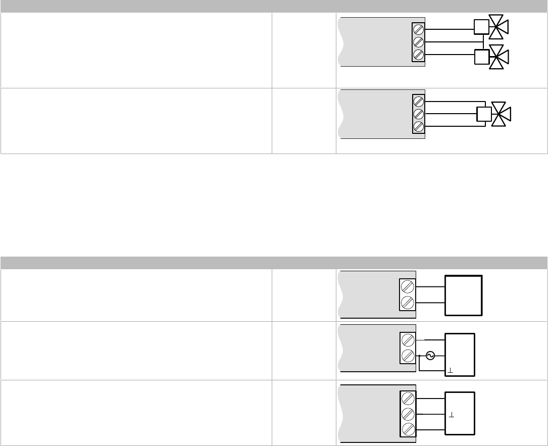
Description Designation Connection Diagram
£ Thermal Valve £ DO5-DO6
DOx
DOx
COM
Thermal Valves
£ Proportional valve: requires two triac outputs £ DO5-DO6
DOx
DOx
COM
Proportional Valve
Analog Outputs
Analog outputs are configured to provide a linear signal ranging from 0 to 10 VDC.
£ Analog output connectors accept wires between 0.75 mm² (18 AWG) and 1.5 mm² (16 AWG).
£ If an analog actuator is being controlled, connect the 0 to 10 VDC output, along with an external 24 VAC power source, to the analog actuator.
£ For ECY-PTU-208: The onboard 24 VAC power supply can be used to power 0-10 V actuators.
£ If functional Earth is connected, analog output circuits will be PELV.
£ If functional Earth is NOT connected, analog circuits will be SELV.
Control Output Type Designation Connection Diagram
£ 0 to 10VDC voltage output. £ AOx
0
-
10
V
Common
AOx
COM
£ 0 to 10VDC voltage output controlling an analog actuator powered by
an external 24VAC power source
£ AOx
AOx
COM
0
-
10
V
~
or
+
Actuator
or
-
24
VAC
£ 0 to 10VDC voltage output controlling an analog actuator powered by
the controller (ECY-PTU-208 only)
£ AOx
AOx
COM
0-
10
V
~
or +
Actuator
or -
24V~
10 / 14
Communications Wiring
The ECLYPSE User Guide provides extensive information and requirements to implement a BACnet IP network. It contains information about network
topology, wire length restrictions, cable type, device IP addressing, radio path planning (when the ECLYPSE Wi-Fi Adapter is connected to the con-
troller), etc. It can be downloaded from our website. For optimal performance, use Distech Controls category 5e network cable or refer to the ECLYPSE
User Guide for cable specifications.
Controllers are uniquely identified on the network by their MAC address. This identifier is printed on a label located on the side of the controller and on its
shipping box. Get a printed copy of the building’s floor plan. During controller installation, peel the MAC address stickers off of the shipping box and put it
on the floor plan where the controller has been installed. This MAC address is used as part of the controller’s factory-default Wi-Fi access point name
and its network hostname.
Bar Code
ID: MAC Address
For example, for a MAC Address of : 76:a5:04:cd:4a:d1
The factory-default name for the Wi-Fi access point is ECLYPSE-CD4AD1
The factory-default hostname is eclypse-cd4ad1.local
Label
Figure9: MAC Address Label Location
There are two methods to connect to the controller: wired (Ethernet connection) or wireless (when the ECLYPSE Wi-Fi Adapter is connected to the con-
troller).
Wired Connection
Network connections can be daisy-chained.
To Next IP
Device
Cat 5
e
Network
Cable
To Router
/
Previous IP Device
RJ-
45
Connector
Figure10: Communications wiring
Wireless Connection
Once the ECLYPSE Wi-Fi Adapter has been connected to the controller, a Wi-Fi hotspot becomes available that allows you to connect to the controller’s
configuration Web interface with your PC.
On your PC’s wireless networks, look for an access point named
ECLYPSE-XXYYZZ
where
XXYYZZ
are the last 6 hexadecimal characters of the con-
troller’s MAC address (see above). The default password for the wireless network is:
eclypse1234

11 / 14
Configuring the Controller
Any of the following methods can be used to connect to the controller’s interface in order to configure it:
£ Using the Xpress
Network
Utility
£ Using the controller’s factory-default Hostname in the Web browser
£ Using the controller’s IP address in the Web browser
Using the Xpress
Network
Utility
The Xpress
Network
Utility is a software application that runs on a PC that allows you to discover all ECY Series controllers connected to an IP network’s
subnetwork or Wi-Fi network and to perform a range of operations on many controllers at once: you can set each controller’s Hostname and IP address,
launch EC-
gfx
Program to program the controller, or you can access the controller’s configuration Web interface. See the Xpress
Network
Utility User
Guide for more information.
Xpress
Network
Companion mobile app can be installed on your smartphone and it works with the QR code marked on the controller’s faceplate which
encodes the controller’s MAC address and host ID. By scanning the QR code, the app records this information to which you assign a hostname. Once
the QR codes for all controllers have been read in, the app‘s information is transferred to the Xpress
Network
Utility where it is used to populate the rele-
vant data fields. See the Xpress
Network
Utility User Guide for more information.
Figure11: Typical QR Code
Using the Controller’s Factory-default Hostname in a Web Browser
Controllers have a factory-default hostname that you can use instead of an IP address to connect to it. The hostname can be used in a Web browser’s
address bar or in the EC-
gfx
Program’s
Connect to
screen. When installing the latest version of EC-
gfx
Program and your PC does not have the Bonjour
service installed, a link to install the Bonjour service is provided. The Bonjour service must be installed on your PC to allow your PC to discover con-
trollers by their hostname.
If your PC is unable to resolve the controller’s hostname, you must connect your PC to the controller through Ethernet or Wi-Fi so that your PC only sees
the controller network. For example, in this case, your PC must be disconnected from all other networks such as a corporate network or the Internet. If
necessary, temporarily disconnect your PC’s network cable from its Ethernet port.
The controller’s factory-default hostname is
eclypse-xxxxxx.local
where
xxxxxx
is the last 6 characters of the MAC address printed on a sticker located
on the side of the controller. See above.
For example, the sticker on the side of a controller shows that its MAC address is 76:a5:04:cd:4a:d1. Connect to the controller’s Web interface as fol-
lows:
1. Open your Web browser.
2. In the Web browser’s address bar, type
https://eclypse-cd4ad1.local
and click go.
3. Login to the controller. Then set the controller’s configuration parameters in the controller’s configuration Web interface. See Connecting to the Con-
troller’s Configuration Web Interface.
Using the Controller’s IP Address in a Web Browser
Connect to a controller through its IP address as follows:
£ For a Wi-Fi Network Connection:
1. Open your Web browser.
2. In the Web browser’s address bar, type
https://192.168.0.1
(the controller’s factory-default wireless hotspot IP address) and click go.
3. Login to the controller. Then set the controller’s configuration parameters in the controller’s configuration Web interface. See Connecting to the Con-
troller’s Configuration Web Interface.
£
For an Ethernet Network Connection
: You must know the controller’s current IP address (from the DHCP server for example).
1. Open your Web browser.
2. In the Web browser’s address bar, enter the controller’s IP address and click go.
3. Login to the controller. Then set the controller’s configuration parameters in the controller’s configuration Web interface. See Connecting to the Con-
troller’s Configuration Web Interface.

12 / 14
Connecting to the Controller’s Configuration Web Interface
At the first connection to an ECLYPSE Controller you will be forced to change the password to a strong password for the admin account to protect ac-
cess to the controller.
In Network Settings, configure the controller’s network parameters so that they are compatible with your network. See the ECLYPSE User Guide for
more information about network settings and how to secure the controller. It is important to create new user accounts with strong passwords to protect
the controller from unauthorized access. Remove the factory default admin account as this is a commonly known security breech (only the password for
this user account needs to be compromized).
Subnet Wiring
Supported Allure Series communicating sensors are connected to the
SUBNET
port modular connector of the controller with a standard Category 5e
Ethernet patch cable fitted with RJ-45 connectors.
The ECLYPSE User Guide provides extensive information and requirements for the connection of an Allure series communicating sensor. It contains in-
formation about network topology and length, cable type, setting the Subnet ID, etc. It can be downloaded from our website. See also the Hardware In-
stallation Guide supplied with the Allure series communicating sensor.
M-Bus Communications Wiring
M-Bus communications are made by connecting meters directly in an M-Bus port.
The controller provides an M-Bus port when connected to an ECY-MBUS extension module via a USB connection.
The M-Bus port must be configured in EC-
gfx
Program prior to use. M-Bus meters are integrated into EC-
gfx
Program using the M-Bus device block.
Maximum M-Bus Device Wiring Length
The following information provides wiring limitations for M-Bus devices. The wiring length provided below was tested as a worst-case scenario with all
meters being located at the end of the bus. If meters are more evenly spaced along the bus, then the maximum wiring length can possibly be increased.
Testing Conditions:
Current per slave/meter 1.5 mA
Max ∆V accepted on the bus 2 V
Cable capacity 110 nf/km
USB Connection:
M-Bus Meters AWG 15 AWG 22
300 Bps 2400 Bps 9600 Bps 300 Bps 2400 Bps 9600 Bps
3 12000 m (39370 ft) 4500 m (14763 ft) 2400 m (7874 ft) 4000 m (13123 ft) 2200 m (7217 ft) 1150 m (3773 ft)
Table1:
Maximum Wiring Length from the Controller to the Last M-Bus Meter on USB connection

13 / 14
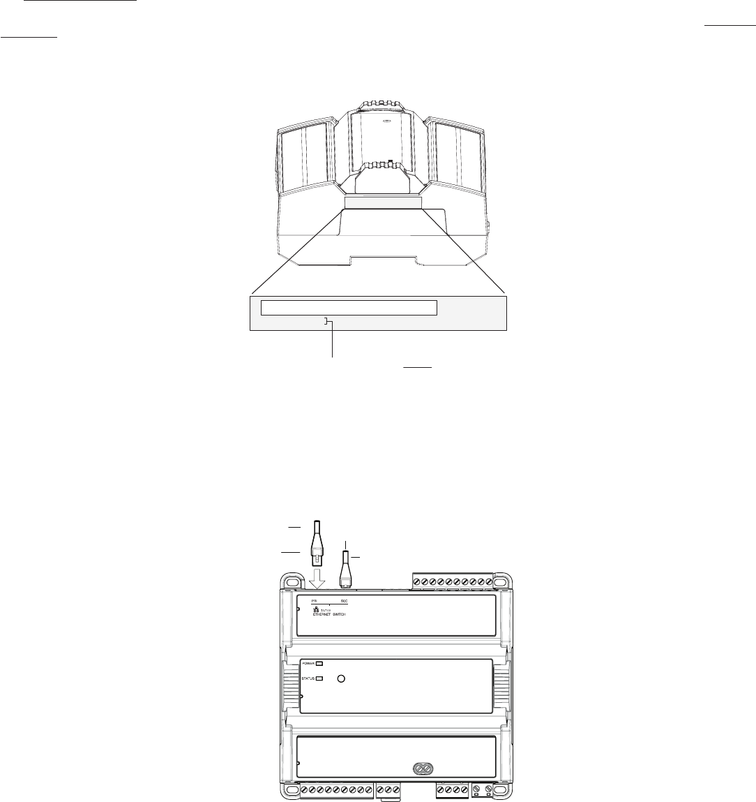
Using the Reset Button
The reset button is located under the controller’s cover. Depending on the amount of time the reset button is held down, different actions are taken by the
controller. The STATUS LED will turn off after each time interval.
SUBNET
HOST
POWER
SEC
PRI
INPUTS
RESET
OUTPUTS
Figure12: Reset button location
Hold Reset For To
5 seconds Restart / reboot the controller.
10 seconds Reset both Ethernet and Wi-Fi IP addresses back to factory default settings.
20 seconds Reset the controller to its factory default settings. User accounts (user names and passwords) will also be reset to the
factory default settings and the controller license will be cleared.
If FIPS has been enabled on the controller, this will turn FIPS off.
Always backup the controller's license through the controller's Web interface before you hold the controller’s
reset button for 20 seconds. Once the controller reboots, you will have to install the license through the
controller's Web interface.
After you hold the controller’s reset button for 20 seconds, the controller’s HTTPS security certificates will be
regenerated. If you use HTTPS to connect to the controller, you will no longer be able to connect to the controller
from any PC that was used in the past to connect to the controller unless you delete the old HTTPS security
certificate from these PCs.
Complementary Information
£ This device is designed for type 1 action
£ This device is designed for type 1.b action
£ This device presents an A class software
£ The EMC immunity test has been passed using 230 VAC and 0.5 A.
£ The Ball Pressure Test temperature is 167°F (75°C)
£ The SELV/PELV does not exceed 42 VDC
£ The maximum accessible voltage is 35 VDC.
£ All traveling cables permanently installed present an X type anchor.
£ All cables must be able to operate above 176°F (80°C)
£ This product is not repairable. If the device is physically malfunctioning or requires repair, it must be returned to Distech Controls.
£ Pollution Degree 2
£ Overvoltage Category II - 2.5 kV

14 / 14
ECY-PTU_IG_21_EN
Maintenance
Regular Maintenance
Each controller requires minimal maintenance, but it is important to take note of the following:
£ Clean the outside of the controller by polishing it with a soft dry cloth.
£ Using a torque limited screw driver set to 0.4 Nm (3.54 in-lb), retighten terminal connector screws annually to ensure the wires remain securely at-
tached.
Disposal
The Waste Electrical and Electronic Equipment (WEEE) Directive sets out regulations for the recycling and disposal of products. The WEEE2002/96/EG
Directive applies to standalone products, for example, products that can function entirely on their own and are not a part of another system or piece of
equipment.
For this reason Distech Controls products are exempt from the WEEE Directive. Nevertheless, Distech Controls products are marked with the WEEE
symbol , indicating devices are not to be thrown away in municipal waste.
Products must be disposed of at the end of their useful life according to local regulations and the WEEE Directive.
North American Emissions Compliance
United States
Changes or modifications not expressly approved by Distech Controls could void the user's authority to operate
the equipment.
This equipment has been tested and found to comply with the limits for a Class B digital device, pursuant to Part
15 of the FCC Rules. These limits are designed to provide reasonable protection against harmful interference in
a residential and commercial installation. This equipment generates, uses and can radiate radio frequency
energy and, if not installed and used in accordance with the instructions, may cause harmful interference to radio
communications. However, there is no guarantee that interference will not occur in a particular installation. If this
equipment does cause harmful interference to radio or television reception, which can be determined by turning
the equipment off and on, the user is encouraged to try to correct the interference by one or more of the following
measures:
Reorient or relocate the receiving antenna.
Increase the separation between the equipment and receiver.
Connect the equipment into an outlet on a circuit different from that to which the receiver is connected.
Consult the dealer or an experienced radio/TV technician for help.
Canada
This Class (B) digital apparatus meets all the requirements of the Canadian Interference-Causing Equipment Regulations.
Cet appareil numérique de la Classe (B) respecte toutes les exigences du Règlement sur le matériel brouilleur du Canada.
Specifications subject to change without notice.
ECLYPSE, Distech Controls, the Distech Controls logo, EC-Net, Allure, and Allure UNITOUCH are trademarks of Distech Controls Inc. BACnet is a registered trademark of ASHRAE; BTL is a registered
trademark of the BACnet Manufacturers Association. The Bluetooth
®
word mark and logos are registered trademarks owned by Bluetooth SIG, Inc. and any use of such marks is under license. All other
trademarks are property of their respective owners.
©, Distech Controls Inc., 2016 - 2024 All rights reserved.
Global Head Office - 4205 place de Java, Brossard, QC, Canada, J4Y 0C4 - EU Head Office - ZAC de Sacuny, 558 avenue Marcel Mérieux, 69530 Brignais, France
