
APPROVED FOR PUBLIC RELEASE
Reliable Software Statement of Work
Language Guidance
December 2022
Report No. FCDD-AMR-MR-22-08
Reliability, Availability, and Maintainability
Engineering and System Assessment Division
Systems Readiness Directorate
U.S. Army Combat Capabilities Development Command
Aviation & Missile Center
Redstone Arsenal, Alabama 35898-5000
APPROVED FOR PUBLIC RELEASE
Reliable Software Statement of Work Language Guidance
Report No. FCDD-AMR-SR-22-08
Foreword
This document provides the guidance for reliability engineers who are responsible
for writing statement of work language for reliability, availability, and maintainability.
The guidance is for selecting the relevant tasks for reliable software based on the type
and size of the program, current phase of acquisition, and maturity of the software.

APPROVED FOR PUBLIC RELEASE
i
EXECUTIVE SUMMARY
This document provides guidance for the reliability engineer(s) who are responsible
for generating reliable software requirements into the Statement of Work (SOW). This
guidance addresses:
• Selecting the relevant tasks for reliable software based on the type and size of
the program, current phase of acquisition, and maturity of the software.
• Tailoring the language for those tasks based on how much software is in the
system, the degree to which the software can contribute to a mission failure, how
high the reliability requirement is, the complexity of the system and software, the
contractor’s capabilities, the risks imposed by changes to the mission, hardware
or interfaces, and other factors.
The guidance document is applicable for weapon and combat systems, and the
mission systems that support weapon and combat systems. This guidance document is
not intended for or use with enterprise or business systems acquisitions (electronic mail
systems, accounting systems, travel systems, and human resources databases).
This guidance and the tailoring of the SOW language is intended for “software
intensive” systems. The Defense Acquisition University definition is “A system in which
software represents the largest segment in one or more of the following criteria: system
development cost, system development risk, system functionality, or development
time.”
1
The term software intensive is applied more broadly in this document. Any
weapon or combat system with software is considered to be software intensive for this
SOW document. Most modern weapon and combat systems have software and are
therefore software intensive for the purposes of this guidance document. The reliability
engineer can determine from the software engineering counterpart if the system is
software intensive.
This document is intended to address the following lessons learned about unreliable
software:
• The system reliability is not meeting specifications because of software failures.
• The Department of Defense (DoD) is finding out far too late in development and
test that system requirements are not being met due to the software.
• Software intensive systems have too many restarts, resets, and/or reboots which
collectively cause the system to be down longer than required.
The goals for this document are:
1
https://www.dau.edu/glossary/Pages/Glossary.aspx#!both|S|28508
APPROVED FOR PUBLIC RELEASE
ii
• Provide insight into the software development artifacts and activities so that the
Government can independently assess both the software artifacts and the
contractor’s ability to make the software mission ready.
• Define acceptable system metrics supported by Reliability and Maintainability
(R&M) to measure and evaluate (define how software related failures impact
current R&M system metrics).
• Implement effective R&M requirements and metrics into software development
programs that are employing Development, Security, and Operations
(DevSecOps).
• Contract for reliable software and effectively evaluate the risks of contractor’s
proposal to achieve reliable software.
• Differentiate roles, responsibilities, and interactions of reliability, software, and
systems engineering.
• Provide for a contractual means for using lessons learned for reliable design to
build software that is more failure resistant and fault tolerant.
• Reduce the occurrence or impact of software failures during operation.
Software does not wear out like hardware. However, software does cause failures
due to hundreds of different root causes. Software does not have to be “down” to cause
a major function failure. The software can cause failures even when operating by:
• Executing irreversible actions or decisions that contribute to a hazardous event.
• Executing a required function the wrong way.
• Executing the function at the wrong time or order.
• Inadvertently executing a function in the wrong state.
• Not executing a function at all when commanded.
• Inability to detect and recover from faults in itself and the system.
• Degraded function or malfunction for the subsystems, components, and
interfaces
Due to the immense size of today’s complex software intensive systems, finding all
the root causes in development and test is a challenge due to time and budget
constraints. For software, the likelihood of each failure is driven by:
• How detectable the underlying defect is in development and test.
• Whether there are any controls over the failure.
• The level of rigor of the test activities.

APPROVED FOR PUBLIC RELEASE
iii
TABLE OF CONTENTS
1.0 Summary of Reliable Software Tasks and Tailoring Guidance ..................... 1
1.1 Reliable Software Program Plan (RSPP) Task ............................................. 7
1.2 Inclusion of Software in System Reliability Model Task ................................ 9
1.3 Reliable Software Allocations Task ............................................................ 13
1.4 Reliable Software Prediction Task .............................................................. 17
1.5 Reliable Software Evaluation Task .............................................................. 21
1.6 Software FMEA (SFMEA) Task ................................................................... 26
1.7 Inclusion of Software in FRACAS Task ...................................................... 36
1.8 Software Reliability Risk Assessment Task ................................................. 38
1.9 Testing for Reliable Software Task ............................................................. 40
2.0 Customer and Contract Reliability Requirement ............................................. 46
3.0 Section L ......................................................................................................... 46
4.0 Section M ........................................................................................................ 47
Appendix A DoD Acquisition Pathways .................................................................. 48
Appendix B Common Defect Enumeration (CDE) .................................................. 51
Appendix C Document Summary List and CDRLs ................................................ 153
Appendix D Terms and Definitions ....................................................................... 162
List of Tables
Table 1-1 Reliable Software Tasks ............................................................................ 1
Table 1-2 Tailoring for Level of Rigor for MCA and MTA Acquisition Paths ............... 6
Table 1-3 Allocation methods for software ............................................................... 14
Table 1-4 Summary of prediction models for software ............................................. 19
Table 1-5 Software FMEA points of view ................................................................. 28
Table 1-6 Tailoring the SFMEA SOW language ...................................................... 29
Table 1-7 Reliable Software Testing Examples ....................................................... 42
Table 1-8 Justification and Applicability for Reliable Software Tests ....................... 44
List of Figures
Figure 1-1 Top Level Decision Tree for Determining Which Reliable Software Tasks
are Relevant for MCA program ............................................................... 2
Figure 1-2 Top Level Decision Tree for Determining Which Reliable Software Tasks
are Relevant for MTA program ................................................................ 3
Figure 1-3 Tailoring for Level of Rigor for MCA and MTA Acquisition Paths .............. 6
Figure 1-4 Agile Software Development .................................................................. 22
Figure 1-5 Defect Discovery Profile ......................................................................... 23
Figure 1-6 Example of a Defect Discovery for Incremental Development ................ 23
Figure 1-7 Example #2 of a Defect Discovery for Incremental Development ........... 24
Figure 1-8 Venn diagram of Coverage via Various Test Methods ........................... 41

APPROVED FOR PUBLIC RELEASE
1
1.0 Summary of Reliable Software Tasks and Tailoring Guidance
This section provides the Government reliability engineer the reliable software tasks,
rationale, and tailoring guidance applicable to Major Capability Acquisition (MCA) and
Middle Tier Acquisition (MTA). The “Software Acquisition Pathway” should use the
MCA pathway guidance in this document. Reliable software tasks are in Sections 1.1 to
1.9. The guidelines (see example SOW language for each task) are as follows:
• The Statement of Work language is italicized. Any language that can be
removed will be bolded.
• Instructions for removing language is contained in <>.
• Undo “bolding” prior to placing the language in the SOW.
• Remove all <> text prior to placing the language in the SOW.
1.0.1 Reliable Software Task and Rationale.
Table 1-1 below summarizes the reliable software tasks and rationale for the below
tasks for a successful acquisition.
Tasks
Rationale
Reliable Software
Program Plan (Section
1.1)
Ensures the tasks required for reliable software are
integrated with the engineering processes and the software,
reliability, and systems engineering personnel interact.
Inclusion of Software in
System Reliability
Model (Section 1.2)
Ensures the software is integrated into the system reliability
model to avoid underestimating the system reliability.
Reliable Software
Allocations (Section
1.3)
Ensures the software is not ignored in the system reliability
allocations and the software team knows to test a specific
reliability goal.
Reliable Software
Predictions (Section
1.4)
Ensures the contractor is predicting reliable software early in
development while there is still time to determine alternative
solutions.
Reliable Software
Evaluation (Section 1.5)
Ensures the contractor demonstrates software under test is
trending to meet or exceed the reliable software allocation.
Software Failure
Modes, Effects,
Analysis (FMEA)
(Section 1.6)
Identifies failure modes in the software that are exceedingly
difficult to identify during testing but are costly in terms of
mission failures.
Inclusion of Software in
FRACAS (Section 1.7)
Ensures the contractor is providing all software failures to
the Government for review.
Reliable Software Risk
Assessment (Section
1.8)
Ensures commonly overlooked risks do not derail the
reliability of the software.
Reliable Software
Testing (Section 1.9)
Provides confidence the software has been exercised in a
manner consistent with its operational use.
Table 1-1 Reliable Software Tasks

APPROVED FOR PUBLIC RELEASE
2
1.0.2 MCA Reliable Software Relevant Tasks Decision Tree (Figure 1-1).
The Figure 1-1, decision point #1 assesses whether the program is software
intensive and the software is mission critical. For most modern combat/weapon/mission
systems this will be affirmative. The Defense Acquisition University definition is “A
system in which software represents the largest segment in one or more of the following
criteria: system development cost, system development risk, system functionality, or
development time.”
2
The definition of software intensive for this document is broader
than the DAU definition. Any weapon or combat system with software is in scope for
this document. If there is any doubt, the reliability engineer should discuss the program
with the software and systems engineering counterpart.
Figure 1-1 Top Level Decision Tree for Determining Which Reliable Software
Tasks are Relevant for MCA program
The Figure 1-1, decision point #2 is to determine if the program is beyond the
Material Solutions Analysis (MSA) phase. Typically, there is software development in
the MSA phase and the relevant tasks for Technology Maturation & Risk Reduction
(
TMRR) or Engineering and Manufacturing Development (EMD) are relevant for MSA.
If a specific reliability objective is not yet established in MSA, reliable software tasks are
still relevant. The software FMEA and risk assessment tasks are not tagged to a
specific quantitative objective.
2
https://www.dau.edu/glossary/Pages/Glossary.aspx#!both|S|28508
APPROVED FOR PUBLIC RELEASE
3
If the software development has not started in MSA, only the reliable software risk
assessment and coordination of reliability and software personnel are relevant (Figure
1-1, decision point # 3).
If software development has started and has not entered either Production and
Deployment or Operations and Support Phase (Figure 1-1, decision point #4), then all
reliable software tasks are relevant and should be tailored as per sections 1.1 to 1.9.
If the phase is either Production and Deployment or Operations and Support and
there are still software development activities (Figure 1-1, decision point #5), then all
reliable software tasks are relevant and should be tailored as per sections 1.1 to 1.9.
If development is complete (i.e., there are no more sprints) but the reliability
objective has not been met (Figure 1-1, decision point #6), then it is too late for the
reliable software predictions or Software FMEA (SFMEA) to be a benefit by influencing
the design.
If the reliability objective has been met by the software and there are no more
planned Engineering Change Proposals (ECP), major changes or new capabilities
planned (Figure 1-1, decision point #7), then the reliable software tasks are not relevant;
If this is not true, then all the reliability tasks are relevant and should be tailored.
1.0.3 MTA Reliable Software Relevant Tasks Decision Tree (Figure 1-2).
The MTA decision path for reliable software starts out similarly to the MCA path -
only programs performing a mission critical function for a combat, weapon, or mission
system are subject to the reliable software tasks. The Figure 1-2, decision point #1,
determination of software intensive for MTAs is the same as MCA (Refer to MCA
Section 1.0.2).
The Figure 1-2, decision point # 2 is whether the MTA will transition to an MCA. If
so, then the MCA decision tree (Section 1.0.2) should be used.
The Figure 1-2, decision point # 3 is whether the MTA program is Rapid Prototyping
(RP) or Rapid Fielding (RF).
If the MTA program type is RP and a direct transition to deployment is planned
(Figure 1-2, decision point #4), then several of the reliable software tasks may require
tailoring because of the lack of calendar time. See Appendix A for an illustration of this
DoD Acquisition pathway.
If the RP will transition to RF, then the tasks should be tailored as if the program is
RF. If the software development is complete (final sprint) then the remaining decisions
are similar to Figure 1-1, decision points # 5-7 (MCA Section 1.0.2). If the development
is not complete (Figure 1-2, decision point #5), then the reliable software tasks must be

APPROVED FOR PUBLIC RELEASE
4
tailored to fit into the five (5) year calendar time requirement for MTA. The tasks in
Sections 1.1 to 1.9 are tailored within the MTA timeframe and some tasks might be
removed if the calendar time available is particularly short. This will be discussed later
in this section.
The Defense Acquisition University definition is “A system in which software
represents the largest segment in one or more of the following criteria: system
development cost, system development risk, system functionality, or development
time.”
3
The definition of software intensive for this document is broader than the DAU
definition. Any weapon or combat system with software is in scope for this document. If
there is any doubt, the reliability engineer should discuss the program with the software
and systems engineering counterpart.
Figure 1-2 Top Level Decision Tree for Determining Which Reliable Software
Tasks are Relevant for MTA program
1.0.4 Level of Rigor for MCA and MTA Pathways
Table 1-2 summarizes the tailoring scheme for the Level of Rigor (LOR) for the MCA
and MTA pathways. For most of the tasks, there are minimalistic or detailed
approaches available. Depending on the phase of the program, the complexity of the
software, and other factors, the LOR can be selected. This table assumes that the
program is software intensive and has mission critical software.
3
https://www.dau.edu/glossary/Pages/Glossary.aspx#!both|S|28508
APPROVED FOR PUBLIC RELEASE
5
For MTA programs that do not transition to MCA, all the reliable software tasks
should be tailored for minimal metrics or minimalistic models. However, further tailoring
may be needed due to the limited calendar time available for the tasks. The tasks with a
√ are generally not costly and can be complete with relatively short calendar time. As
for the other tasks, below is a ranked order of importance to MTA programs:
1. Testing for reliable software for mission critical software Line Replaceable
Units (LRUs) (Section 1.9). The best way to achieve reliable software is to test
the trajectories, boundaries, faults, data, zero values, etc. This task alone
provides the most confidence in the reliability of the mission critical software.
2. Reliable software evaluation (Section 1.5). If the software is highly unstable,
this evaluation will make that noticeably clear. This evaluation will identify the
additional test effort to make the software stable but does not guarantee that the
contractor has or will test the inputs that are most likely to result in a software
failure. This task should always be in addition to the testing for reliable software
and not instead of it.
3. Top level SFMEA (Section 1.6). This task can identify top level failure modes
that should be considered in testing. However, without the testing for reliable
software task the tests might not be executed.
For MCA programs with limited time or funding, the above tailoring scheme can be
applied.

APPROVED FOR PUBLIC RELEASE
6
Reliable
Software Tasks
MCA or MTA with
transition to MCA
path
MTA RP path with
direct transition to
deployment
MTA RP transition to
RF path
MTA RF path
Reliable Software
Program Plan
√
√
√
√
Inclusion of
Software in
System Reliability
Model
Model type can be
tailored to complexity
of SW/HW
1
Can be tailored for
simple model
1
Can be tailored for
simple model
1
Can be tailored for
simple model
1
Reliable Software
Allocations
Model selected based
on accuracy/
availability of data
1
Can be tailored for
simple model
1
Can be tailored for
simple model
1
Can be tailored for
simple model
1
Reliable Software
Predictions
Select models
depending on risk
2
Either remove task or
use simplest models
2
Either remove task or
use simplest models
2
Either remove task or
use simplest models
2
Reliable Software
Evaluation
Full or minimal metric
set depending on risk
3
Full or minimal metric
set depending on risk
3
Full or minimal metric
set depending on risk
3
Full or minimal metric
set depending on risk
3
Software FMEA
Tailored by risk.
4
Tailored by risk.
4
Tailored by risk.
4
Tailored by risk.
4
Inclusion of
Software in
FRACAS
√
√
√
√
Reliable software
risk assessment
√
√
√
√
Reliable software
testing
Tailored to apply to the most mission critical software LRUs
Table 1-2 Tailoring for Level of Rigor for MCA and MTA Acquisition Paths
√
- Applicable anytime there is mission critical software intensive system
1
-
Applies
if either the reliable software predictions or reliable software evaluation is
relevant
2
- Most useful early in the program. Not useful if the coding activities are complete.
3
-
Unless the reliability objective has been demonstrated this task is relevant.
4
-
Most useful before code is complete. Not useful if all testing is complete.
Figure 1-3 illustrates the process for how the reliable software tasks interface with each
other.

APPROVED FOR PUBLIC RELEASE
7
Figure 1-3 Tailoring for Level of Rigor for MCA and MTA Acquisition Paths
1.1 Reliable Software Program Plan (RSPP) Task
The RSPP documents the contractor’s plan for executing the reliable software tasks.
The following sections provide the basis / justification for the task and tailoring the SOW
language to the Acquisition Strategy.
1.1.1 Basis / Justification
Without the RSPP, there is no means for the government to assess the contractor’s
plan for reliable software. For example, the contractor may be planning to use “subject
matter expertise” for all reliable software tasks. By having a written plan, the
government will know in advance that the contractor is taking a high-risk approach. The
RSPP is not a cost driver, the tasks selected drive cost.
1.1.2 Tailoring the RSPP SOW Language
For maximum effectiveness, the RSPP must be integrated with the hardware
reliability plan and clearly referenced in the contractor’s Software Development Plan
(SDP). The contractor’s reliability engineers are to coordinate with the contractor’s
software personnel to ensure that the RPP RSPP section is referenced from the SDP.
The reliability engineer must tailor the SOW language per the following steps:

APPROVED FOR PUBLIC RELEASE
8
Step 1: Determine which reliable software tasks are relevant for the program as per
Figures 1-1 or 1-2 and/or Table 1-2. The SOW language for the RSPP is not affected
by the development framework. The tasks selected are affected by Agile / DevSecOps.
Step 2: Modify the RSPP SOW language:
• Remove any bolded tasks from the SOW language that are deemed to be
not relevant as per the applicable decision tree.
• Remove this text <writer shall remove items as per the guidance>
• If either condition below is not true, then remove (11) site reliability
engineer from the SOW language for the RSPP. Unless the
weapon/system is a providing network capability, the site reliability engineer
is likely to be out of scope for the program.
• Software downtime requires immediate action by on site engineer.
• The site reliability engineer is funded by the program.
• The RSPP section of the Reliability, Availability, and Maintainability Program
Plan (RPP) must be explicitly referred from the SDP to ensure the software
engineering is aware of the reliability requirements and is working to meet
the requirements. The Data Item Description (DID) for the SDP is DI-IPSC-
81427 Rev. B. This may require SOW language for the SDP.
Step 3: Merge the RSPP language with the reliability program plan language for the
hardware in the SOW.
The RSPP SOW language as follows:
“The contractor shall provide the Government an overview of their system reliability
program that includes scope to develop reliable hardware and software, as a briefing at
the Post-Award Orientation. The reliable software program shall address: <writer shall
remove items as per the guidance> 1) inclusion of software in the reliability
model; 2) reliability allocations for software; 3) the method for predicting reliable
software; 4) demonstrate reliability curves of the software in a diverse operational
environment; 5) the method to identify and mitigate software failure modes early
in development; 6) software failure mode and defect identification, tracking and
resolution; 7) software risk management; 8) the methods for development and
testing of reliable software; 9) coordination of the reliability, test, design, systems,
software, embedded software functional areas; 10) the integration of reliable software
tasks into the software development schedule to ensure that reliability is designed in
early; and 11) site reliability engineer. The contractor shall identify all mission critical
software LRUs and functions. The contractor shall describe the planning and
implementation of reliable software activities as well as coordination with reliability, test,
design, systems, software, and embedded software. The contractor shall integrate the
reliable software effort with the overall system reliability program. The contractor shall
participate and be prepared to share any reliable software task updates during the
government working group meetings per the program integrated master schedule
Reliability & Maintainability Working Group. The contractor shall reference the RSPP in
the software development plan. The contractor shall deliver the Reliable Software
Program Plan (RSPP) as part the R&M Program Plan (RPP) per DI-SESS-81613.”

APPROVED FOR PUBLIC RELEASE
9
1.1.3 Tailoring the Contract Data Requirements List (CDRL) (DD Form 1423)
See Appendix C for the CDRL template. Steps for tailoring as follows:
Step 1: Do not create a separate CDRL for software. Insert language for both the
hardware reliability and reliable software plans in the same CDRL for the R&M Program
Plan, DI-SESS-81613.
Step 2: All information related to due dates, frequency, and government approval
shown in Appendix C CDRLs are recommendations. The reliability engineer should
complete all blocks based on program-specific information. Coordinate with the
software engineering counterpart so that this deliverable coincides with the SDP.
Step 3: Coordinate with the software engineering counterpart and ensure that the
reliability engineer’s office symbol is placed into block 14 of the SDP CDRL. The DID
for the SDP is DI-IPSC-81427.
Step 4: Remove any shaded text within <>
1.2 Inclusion of Software in System Reliability Model Task
The System Reliability Model (SRM) is a graphical depiction of the system with an
underlying analysis, such as the Markov model, Sequence Diagram, Mission model,
Reliability Block Diagram (RBD) and / or Fault Tree Analysis (FTA). The initial delivery
of the model must meet the Government’s requirements to include all software
components in an appropriate manner and the structure of model includes relationship
between software and hardware components prior to approval. The following sections
provide the basis / justification for the task and tailoring the SOW language to the
Acquisition Strategy.
1.2.1 Basis / Justification
Systems may be represented by more than one model. For example, software
operated at discrete mission times may be best represented by a mission model while
software operating continuously may be best represented by a Markov model. The
analysis identifies critical weaknesses in the system design which impact reliable
software. The following are lessons learned if the contractor is not required to explicitly
list the software LRUs in the system reliability model. Reliable Software is often
disregarded / under resourced / inadequate mission reliability testing resulting in failure
to achieve mission reliability:
• Software is entirely missing from the SRM.
• Software can be partially missing. For instance, the reused or commercial
off the shelf (COTS) software might not be represented on the SRM.
APPROVED FOR PUBLIC RELEASE
10
• Software is represented on the SRM but represented as one big block. With
today’s exceptionally large and complex systems, the software is almost never
architected in one big LRU. Some software LRUs rarely need updating while
others are continually evolving with capabilities. By designing the system with
independent software LRUs, the software organization can update one LRU
without affecting the other software capabilities and functionality. The reliability
engineers often represent several software LRUs as one reliability block without
consideration of varying duty cycles or interactions. The system models provide
for a means to model the software LRUs more closely with a true operational
profile.
Including software on the system reliability model requires the government reliability
engineer to determine the Figure of Merit (FOM) in accordance with Section 1.2.2. This
allows the contractor to:
• Understand the interaction of software LRUs with the rest of the components in
the system.
• Ensure software engineering develops block diagrams as part of software
architecture. Most of the mathematical effort is conducted in the reliable software
predictions and reliable software evaluation tasks. Hence, this task, excluding
the work required to assign quantitative values, is a relatively small cost. Various
automated tools are used for system reliability modeling.
• Assess the reliability of each software LRU either via the predictions or the
reliability evaluation curves.
Cost / Schedule Impact: The software LRUs should be defined at the highest level
for the contractor to propose, therefore putting the LRUs into the system reliability
model should result in minimal to no cost or schedule impact to this task.
1.2.2 Identifying Specific FOM
If the result Figures 1-1 or 1-2 and/or Table 1-2 determines reliable software model
task is relevant, the government reliability engineer needs to identify the FOM in the
SOW language. For example, if availability and Mean Time Between Essential Function
Failures (MTBEFF) are required to be measured then place the metrics into the SOW
identified by < >. FOM examples as follows:
• “Reliability” is the probability of success over some specific mission time. This
measure is applicable for any software involved with a “mission.” This would
include missiles, aircraft, landing gear, vehicles, etc. However, if the mission
is an extended duration, “availability” typically makes more sense. Example:
Refrigerators are always on. Dishwashers are only on for discrete time
periods (missions) per day.
• “Availability” is appropriate for systems that are on for an extended duration,
such as security systems, networks, radar, or any system that does continuous

APPROVED FOR PUBLIC RELEASE
11
monitoring. Availability measures the downtime for preventive and restorative
actions. To predict software availability, the restore time must be predicted.
• “Mean Time to SoftWare Restore (MTSWR)” is the metric to measure software
downtime. This includes time to: 1) restart, 2) reboot, 3) workaround, 4)
reinstall software, 5) downgrade software, and/or 6) wait for a software
upgrade. These are listed in relative order of time required. Not all software
failures can be addressed with a restart or reboot. Some may need to be
avoided with a workaround. In a few rare cases, some issues are resolved by
reinstalling the software. In cases in which a new version of software has
defects not seen in prior releases, the software might have to be downgraded.
In some cases, in which a software failure cannot be avoided or worked
around and effects the mission the software might not be used until the
software engineering team fixes the problems and deploys an upgrade. Mean
Time to Repair (MTTR) does not apply to software because software does not
wear out.
• “Mean Time Between System Abort (MTBSA), MTBEFF, etc. and failure rate”
can be measured for any software system.
• “Total predicted software defects” is valid metric for contractor Development
Tests (DT) and/or field operation. While the predicted software defects cannot
be necessarily merged with hardware predictions, the software defect
prediction can be a useful indicator for validating the other predictions. If the
contractor’s predictions for defects are unreasonable (i.e., very close to 0 for
example) then the contractor prediction for failure rate, availability will also be
unreasonable.
1.2.3 Tailoring the SOW Language
Step 1: If the result of the decision tree in Figures 1-1 and 1-2 and/or Table 1-2 is
that software does not need to be included in the system reliability model then do not
include the entire SOW language. Otherwise, the reliability engineer must tailor the
SOW language per the following steps:
Step 2: Modify the SOW language by removing any bolded tasks from the SOW
language that are deemed to be not relevant as per the applicable decision tree.
Step 3: Determine the reliability Figure of Merit as per section 1.2.2. and <Insert the
selected figures of merit here as per guidance> in the SOW.
Step 4: If any of the below are true, the more complex models; such as the event
sequence diagrams, fault trees, Markov and mission models; are more appropriate than
the simpler models such as the reliability block diagram. In that case, make sure to
include all the choices in this statement. 3) generate event sequence diagrams, fault
trees, Markov models, reliability block diagram and/or mission models.

APPROVED FOR PUBLIC RELEASE
12
• Complex interactions between hardware and software or software and software
• The software LRUs are not up all the time.
• There is redundancy in the hardware.
• There is N version programming (This is essentially redundant software which is not
very common due to the very high cost.)
• Highly fault tolerant software
• The system and software are difficult to represent without a system model
Step 5: SOW Language is as follows:
“The contractor shall 1) incorporate all software Line Replaceable Units (LRUs)
including deployed custom software, commercial off the shelf (COTS), Free Open
Source Software (FOSS), embedded software as defined by the IEEE 1633 2016
clause 5.1.1.1 into the overall System Reliability Model (SRM) IAW DI-SESS-81496; 2)
Describe how the <Insert the selected figures of merit here as per guidance> will be
documented for comparison against system requirements; 3) generate event sequence
diagrams, fault trees, Markov models, reliability block diagram and/or mission models to
identify mission critical SW. IEEE 1633 2016 clause 5.3.4 and System and Software
Reliability Assurance Notebook FSC-RELI chapters 4 and 5 provide guidance.
The Software components identified in the SRM shall be traceable and consistent
with the software components identified in the software design. System reliability
models shall explicitly identify software LRUs. The SRM shall be used to: 1) generate
and update the reliable software allocations, and 2) identify critical software items and
additional design or testing activities required to achieve the reliable software
requirements. Critical items are defined as those items whose inoperability impacts
mission completion, essential functions per the Failure Definition Scoring Criteria
(FDSC), Preliminary Hazards Analysis (PHA), Functional Hazards Analysis (FHA), or
items whose failure rates contribute significantly to the overall system degradation. The
contractor shall keep the models up to date and be prepared to share any updates
during working group meetings.”
1.2.4 Tailoring the CDRL
See Appendix C for the CDRL template. Steps for tailoring as follows:
Step 1: Do not create a separate CDRL for software. Insert language for both the
hardware and software system reliability model in the same CRDL for Reliability and
Maintainability (R&M) Block Diagrams and Mathematical Models Report, DI-SESS-
81496.
Step 2: All information related to due dates, frequency, and government approval
shown in Appendix C CDRLs are recommendations. The reliability engineer should
complete all blocks based on program-specific information.
Step 3 Remove all shaded text within <>.

APPROVED FOR PUBLIC RELEASE
13
1.3 Reliable Software Allocations Task
This analysis ensures that the portion of the system reliability requirement is
allocated appropriately to the software LRUs. Allocations are an ongoing process which
goes hand in hand with the reliability modeling activity.
Allocation can be made based on several different techniques as illustrated in Table
1-3. IEEE 1633 Recommended Practices for Software Reliability, 2016 clauses 5.3.5
and 5.3.8 discusses several methods for allocation. In addition, the System Software
Reliability Assurance Notebook
4
section 6.3 discusses software reliability allocation.
The methods in Table 1-3 are listed in order of preference. Historical data can be
most accurate but is often difficult to acquire and must be from a recently developed
similar system. Test data is relatively accurate if it is from a recent operational test.
Bottom up allocations employ predictive models to establish the allocation so the
accuracy depends on the models selected. Allocating by relative duty cycle is
applicable if there are varying duty cycles among the components. This allows
components that are on the most to receive a proportional allocation. Allocating by
research and development cost or by number of components are the least accurate
methods but are often more accurate than subject matter expert guess.
This task applies to software projects using any development framework that has no
bearing on how each of the software LRUs is allocated its fair share of the system
reliability requirement. The timing of the deliverables may be affected by the
development framework. Note that IEEE 1633 2016 has guidance in clause 4.4 for the
reliable software tasks for agile, incremental and waterfall deliveries. For agile
development, the software specifications are provided in “user stories” as opposed to
“software requirements specifications.”
The work required for the allocations is driven by the model selected. Allocation by
cost and/or the number of LRUs are the least expensive but also least accurate.
However, either of these quick and easy approaches is more accurate than subject
matter expertise. The downside of the allocation by number of LRUs is that it is not
accurate if the reliability engineer assumes that all the software is in one big LRU and if
the software LRUs are significantly bigger in functionality than the hardware LRUs.
4
https://www.cs.colostate.edu/~cs530/rh/secs1-3.pdf

APPROVED FOR PUBLIC RELEASE
14
Allocation Method
Preference
Historical data which indicates X% of the
fielded failures are due to software.
Usually most accurate if the data is recent and
the historical data is from a similar system with
similar mission. While the accuracy of
historical data is typically the best, it’s also
difficult to collect for DoD systems.
Recent testing data which indicates X%
of testing failures are due to the
software.
Relatively accurate if the software is being
tested in an operational environment (with the
target hardware).
Bottom-up allocation – All system
configuration items undergo reliability
assessment. The hardware and software
configuration items are applied to the SRM.
The allocation for software is simply the
predicted failure rate over total of all
predicted failure rates. Even if the
assessment does not meet the system
requirement, the allocation is still the
relative contribution of the prediction to the
system prediction.
The accuracy depends on the models used for
the bottom-up predictions. More inputs to the
model usually mean more accuracy if the
model is used correctly and inputs are correct.
Allocation by duty cycle. The % allocated
to SW depends on the duty cycle of each of
the components in the system.
This model is useful when there is varying
duty cycle of the system components.
Accuracy depends on the accuracy of the
prediction model discussed in the reliable
software prediction task. If historical data is
used, this method is typically accurate.
Allocation by Research and
Development cost. The % of R&D
engineering $ spent on SW versus %
R&D engineering $ spent on HW
Cost is a good indicator of reliable software
but only if the cost is accurately predicted. If
the cost of developing the software
components is in the same range as the cost
of the hardware R&D, then the software
contribution to failure rate is likely to be similar
to the hardware.
Allocation by number of Configuration
Items. Count the hardware LRUs and the
software LRUs. Allocation is based on
relative number of LRUs.
Not as accurate as other methods. There is
much variation on how much code comprises
an LRU. If there are many small LRUs, this
method can over-allocate the software or
hardware. If there is one large software LRU,
this method can under-allocate the software
portion.
Table 1-3 Allocation methods for software
The bottom-up allocation requires using a prediction model. If the SOW requires a
reliable software prediction model, then there is no additional cost in using that
approach. The historical data and recent test data approach are not expensive but are
only useful if the contractor has the historical data. The cost of allocations by duty cycle
depends on the underlying model selected for the predictions.

APPROVED FOR PUBLIC RELEASE
15
The following sections provide the basis / justification for the task and tailoring the
SOW language to the Acquisition Strategy.
1.3.1. Basis / Justification
Reliable Software is often disregarded / under resourced / inadequate mission
reliability testing resulting in failure to achieve mission reliability.
• Contractors allocate too little if any of the system allocation to the software even
though software is a considerable part of most military weapon systems.
• Contractors may allocate part of the system objective to software but have no
means for justifying the allocation - i.e., the “leftover” method in which the
software gets whatever is left over from the hardware prediction.
• Contractors allocate the reliability objective using the “big blob” approach which
makes it difficult to track progress against when there are multiple software LRUs
Reliability engineers often assume that the software gets one big allocation of the
system reliability. Today’s large complex systems almost never have all the software
code in one LRU. One would not allocate all the hardware reliability to exactly one LRU
so this should not be done for software either. Software LRUs may/will be developed by
different teams within the same organization, or different organizations. Some LRUs will
be bigger than others and hence require a larger portion of the allocation. Some LRUs
will execute more often than other LRUs. If the software organization has one big
number to meet for the software, the software organization cannot incrementally work
towards the requirement. But if the allocation is apportioned to each LRU, then the LRU
can be designed to and tested against the allocation. Table 1-3 is a summary of the
some of the industry methods employed for reliable software allocations. Methods that
employ recent historical data are preferred.
1.3.2 Tailoring the SOW language
Step 1: If the result of the decision tree in Figures 1-1 and 1-2 and/or Table 1-2 is
that software does not need to be included in the software allocation task then do not
include the entire SOW language. Otherwise, the reliability engineer must tailor the
SOW language per the following steps:
Step 2: Modify the SOW language by removing any bolded tasks from the SOW
language that are deemed to be not relevant as per the applicable decision tree.
Step 3: Identify and tailor <Identify any components that are out of scope such
as GFE>.
• Identify any boundaries that do not need to be included in the allocations. For
example, Government Furnished Software (GFS) may be included/excluded in
the allocations or interfaces to GFS.
• Replace the above text with any out of scope components.
• If no components are out of scope, remove the above text

APPROVED FOR PUBLIC RELEASE
16
Step 4: Identify any test data and tailor <Use of recent test data is acceptable>
• If this is an MTA program with direct transition to rapid fielding then the contractor
can be advised that using recent test data is acceptable as shown below.
• If recent test data is acceptable then unbold the below text and remove <>
• Otherwise delete the below text.
Step 5: SOW Language is as follows:
“The Contractor shall allocate the system reliability requirement to software LRUs
using allocation methods using IEEE 1633 2016 clause 5.3.8 and Table 28 as a guide.
<Identify any components that are out of scope such as GFE>. <Use of recent test
data is acceptable>. The results of the reliable software allocation shall be
incorporated into the system reliability model. The contractor’s Software Requirements
Specification (SRS) or user story shall include a statement of the numerical reliability
goals (consistent with the system Figure of Merit (FOM) for hardware and system) for
each identified software LRU. For Agile/ Continuous Improvement (CI)/Continuous
Development (CD) framework IEEE 1633 2016 clause 4.4 and Table 16 provide
guidance. The contractor shall keep the allocations up to date and be prepared to
share any updates during working group meetings. The contractor shall deliver the
allocated reliability of the software of each software LRU as part of the Reliability and
Maintainability (R&M) Report IAW DI-SESS-81968.”
Note: The allocations may change for software whenever the predictions or
reliability evaluations change. The reliable software predictions drive the allocations.
Early in the program the size estimations may be volatile and affect the allocations. The
allocations should be revisited by the contractor any time there is a major change in the
size of the software. However, the results do not need to be formerly delivered to the
Government except at formal milestones. The contractor should keep the models up to
date and be prepared to share any updates during working group meetings.
1.3.3 Tailoring the CDRLs
See Appendix C for the CDRL template. Steps for tailoring as follows:
Step 1: Do not create a separate CDRL for software. Insert language for both the
hardware and software system reliability allocation in the same CRDL for Reliability and
Maintainability (R&M) Allocation Report, DI-SESS-81968.
Step 2: All information related to due dates, frequency, and government approval
shown in Appendix C CDRLs are recommendations. The reliability engineer should
complete all blocks based on program-specific information.
Step 3 Remove all shaded text within <>.
Step 4: Ensure that the reliability engineer’s office code is added to block 14 of the
CDRL for the SRS (DI-IPSC-81433).
APPROVED FOR PUBLIC RELEASE
17
1.4 Reliable Software Prediction Task
This task is the prediction of the reliability of the software through comparable
systems software/items, industry models based on historical data of similar systems or
historical reliability from the same system. A “prediction” is conducted early in
development portion of the program. IEEE Recommended Practices for Software
Reliability, 2016 clauses 5.3.2 and 6.2 discusses the reliable software predictions early
in development. This task should be used in conjunction with the SSRM and the
reliable software allocation to quantify the reliable software metrics for each software
LRU and to identify low, medium, and high-risk critical items.
The frequency of the predictions should be the major milestones or annually. The
predicted reliability of the software can and will change more rapidly than the predictions
for hardware for the simple reason that predictions are primarily driven by how much
software is scoped. Software organizations are historically prone to underestimating the
amount of software to be developed. The predictions should be revisited by the
contractor every 6-12 months, at every milestone, or whenever it is demonstrated that
the allocated reliability objective is not being met or whenever there is an ECP. This
frequency applies whether the software is developed in an agile framework or a
waterfall framework. While the contractor should keep the predictions up to date and
make available during reliability working group meetings, the formal report to the
Government should be made at major milestones.
The following sections provide the basis / justification for the task and tailoring
the SOW language to the Acquisition Strategy.
1.4.1. Basis / Justification
Reliable Software is often disregarded / under resourced / inadequate mission
reliability testing resulting in failure to achieve mission reliability.
• Contractors assume that the reliability of the software = 1 or failure rate = 0.
• Contractor assumes that the reliability of the software is part of the hardware
reliability prediction.
• Contractor uses models that were developed more than 20 years ago.
• Contractor uses subject matter expertise which is historically the least accurate
method.
A common myth is time to failure for software cannot be predicted. The reason for
this myth is that reliability engineers are trying to predict the time between the same
failure mode. Software does not wear out. For software, time to failures predictions are
predicting the time in between different and previously unknown failure modes. This is
opposed to predicting the time between the same failure occurring repeatedly.
Predicting the time between the same failure mode only has value when that failure
mode is related to a hardware failure or resource usage. For example, one can
APPROVED FOR PUBLIC RELEASE
18
estimate the time it takes to a hard drive to run out of space because the software was
not designed to overwrite or offload the log files once the drive fills up. For all other
failure modes, the failure occurs based on the mission profile and inputs.
Example: Mean Time to Failure (MTTF) of 100 hours for software means a software
failure previously not detected will occur in the next 100 hours. Software does not wear
out. The MTTF means the time to the next failure due to a different root cause or
defect. Once a software failure occurs, the root cause of the failure (the defect) will
either be corrected by software engineering or avoided by the user until it can be
corrected. MTTF provides no real value to a maintenance engineer because the
maintainer has no idea as to where the software failure will be and the maintainer is not
the person who will ultimately remove the underlying defect when it does manifest into a
failure. However, the prediction does provide value to the software organization
responsible for maintaining the software. The software organization can schedule
software engineering maintenance effort based on the predicted failures per time unit to
ensure that the technical debt (unresolved defects) don’t pileup.
Software can’t fail if it’s not running. Hence, software predictions are not a function
of calendar time. The key parameters that effect reliable software are:
• Total number of inherent defects in the software. This is a function of the total
amount of software and the development practices.
o The amount of software – bigger software systems will have more inherent
defects
o Development factors
The level of rigor by the software development team with regards to
requirements, design, code, unit level, integration level, system
level testing
Software planning, execution, and project management
Defect reduction techniques
Other risks associated with the software such as whether the
software is for a relatively new weapon, availability of software
engineers experienced with the weapon, etc.
• The amount of usage time
• The degree to which the software is exercised in a real environment
Since the amount of the software is key parameter and the software does not fail as
a function of calendar time, reliability software is predicted by determining / estimating
the following:
• Total defects to escape into operation
• Usage time
• Rate at which inherent defects will expose themselves as failures (growth rate)
• MTBEFF as a function of defects, usage time and growth rate
• MTBSA by calibrating the MTBEFF by the percentage of EFFs that are
historically system aborts.

APPROVED FOR PUBLIC RELEASE
19
• MTSWR is used to predict availability.
• Probability of failure as a function of the MTBSA and the known mission time
The models shown in Table 1-4 are methods for predicting either the defect density
or defects in the reliability prediction models. The techniques range from simple to
complex. Typically, the models with more inputs are more accurate than models with
fewer inputs if the inputs to the model are correct.
Prediction
Method
Advantages
Disadvantages
Historical data
from similar
systems
Usually, the most accurate when
calibrated for any differences in
mission or development practices
Many organizations either do
not have any or do not have
processes to collect it
Detailed
assessment
surveys with
several input or
assessment
areas as per the
IEEE 1633
Next to historical data, the detailed
assessment surveys are most accurate
and based on historical data from real
software programs in which the actual
reliability as well as the development
practices are known. Accuracy
depends on 1) number of questions, 2)
ability for organization to answer all
questions accurately, and 3) the age of
the model (Models > 20 years old are
generally not accurate).
Requires contractor’s
software and reliability
people coordinated activities.
Time to complete
assessment depends on the
number of questions and if
the reliability engineer can
get the answers from
software engineering.
Rayleigh model
When based on historical data such as
QSM’s SLIM
5
, these models are
relatively accurate.
Requires contractor’s
software and reliability
people coordinated activities.
Weibull analysis
Generalization of Rayleigh model;
based on program’s own historical
data, not that of comparable systems.
Yields more accurate forecasts in
context. Defect data often readily
available. Widely recognized and
accepted.
Forecasts not reliable until
>60% of defects discovered.
Not reliable in early
development stages.
Requires access to defect
data.
Simple look up
tables based on
application type
or CMMi®
Quick and easy
The least accurate of the
other methods shown above
but significantly more
accurate than subject matter
estimates
Table 1-4 Summary of prediction models for software
This task applies to software projects using any development framework. While the
reliability of the software may be affected by agile development methods, the steps for
assessing the software LRU predictions are not affected by the software development
5
Quantitative Software Management Software Life Cycle Model Management Suite

APPROVED FOR PUBLIC RELEASE
20
framework. The timing of the deliverables may be affected by the development
framework and is discussed in the guidance for the CDRL/1423. Note that IEEE 1633
2016 has guidance in clause 4.4, Tables 16 and 23, clause 5.3.2.4, for the reliable
software tasks for agile, incremental and waterfall deliveries. Clause F.3.3. shows an
example of how predictions are applied in an agile framework.
The cost tailoring for this task depends on the degree of software in the system and
the risk level of that software in terms of stability. Stable programs which are having
relatively small or minor software upgrades are at less risk than a brand-new major
program. This task is not relatively expensive as there are several documented ways to
predict and assess the reliable software using IEEE 1633 2016. Even with the low
relative cost, some models require fewer inputs than others and less work by the
contractor’s reliability engineers to use the model. The government reliability engineer
may specifically allow for the models with fewer inputs if subject matter expertise is not
employed.
1.4.2 Tailoring the SOW Language
Step 1: If the result of the decision tree in Figures 1-1 and 1-2 and/or Table 1-2 is
that software does not need to be included in the system reliability prediction then do
not include the entire SOW language. Otherwise, the reliability engineer must tailor the
SOW language per the following steps:
Step 2: The only model that is not acceptable for a prediction for any program is
“subject matter expertise.” The SOW language as follows:
“The contractor shall predict the reliability of the software of each software LRU.
The contractor shall identify the method and justification for each prediction. The
predictive models discussed in IEEE 1633 2016 clauses 5.3.2, 6.2 and B.2, or historical
data from similar systems is acceptable. Predictions based on subject matter shall not
be used. The contractor shall update the reliable software predictions whenever size
estimations or other factors change and make the updates available to reliability
working groups. The contractor shall conduct reliable software predictions during
development through to testing. IEEE 1633 2016 Tables 16, 23, and clause 5.3.2.4
provide guidance for how the predictions are conducted in an agile/CI/CD framework.
The contractor shall deliver the predicted reliability of the software of each software LRU
as part of the Reliability and Maintainability (R&M) Report IAW DI-SESS-81497.”
1.4.3 Tailoring the CDRL
See Appendix C for the CDRL template. Steps for tailoring as follows:
Step 1: Do not create a separate CDRL for software. Insert language for both the
hardware and software system reliability predictions in the same CRDL for Reliability
and Maintainability (R&M) Prediction Report, DI-SESS-81497.

APPROVED FOR PUBLIC RELEASE
21
Step 2: All information related to due dates, frequency, and government approval
shown in Appendix C CDRLs are recommendations. The reliability engineer should
complete all blocks based on program-specific information.
Step 3 Remove all shaded text within <>.
1.5 Reliable Software Evaluation Task
Reliability growth is the positive improvement in reliability metric over a period of
time due to the implementation of corrective actions. For software, reliability
improvement is a function of:
• Amount of test hours with no new features added to the software system.
• The stability of the reused and off the shelf software components
• The number of installed sites (the number of weapons deployed) during reliability
growth - more installed sites and end users means faster growth while fewer
installed sites usually mean less rapid growth
• Implementation of corrective actions, fix effectiveness, and management
attention.
The Software Reliability Evaluation should measure the:
• Defect discovery due to software failures (increasing, peaking, or decreasing or
some combination)
• Actual reliability of software tracked against reliable software goals
• Capability drops and expected effect on reliability
• Degradation due to test environment, scalability, etc.
This task applies to software projects using any development framework. While the
actual reliability expected for Agile development may be different for Waterfall
development, the steps for tracking reliability is the same regardless of the development
framework.
The following sections provide the basis / justification for the task and tailoring the
SOW language to the Acquisition Strategy.
The reliable software evaluation is conducted during contractor testing as well as
Government testing. The below Figure 1-4 illustrates the agile development process.
The testing is conducted iteratively. The circles represent an iteration of development.
Within each circle is a testing activity. The software reliability is evaluated during each
testing activity of each iteration.
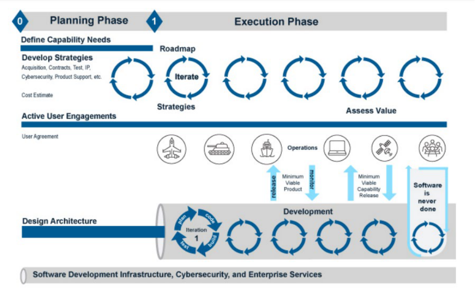
APPROVED FOR PUBLIC RELEASE
22
Figure 1-4 Agile Software Development
1.5.1 Basis / Justification
Reliable Software is often disregarded / under resourced / inadequate mission
reliability testing resulting in failure to achieve mission reliability.
Figure 1-5 illustrates the typical defect discovery profile over the life of a software
version (Only unique defect discoveries graphed). If the contractor deploys the software
before the peak, the software is immature and not suitable for the customer. If
contractor deploys the software between the peak and when the software stabile
(defects flatten out), the software may be usable but not meet the reliability goals. If the
software deploys once the defect discovery rate flattens either the reliability objectives
of the program have been met or are on the path to meeting those objectives.
With Agile/CI/ Continuous Development may or will have multiple peaks with
(ideally) a final burn down at the final sprint. Every time there is a new software version,
there is a new profile.

APPROVED FOR PUBLIC RELEASE
23
Figure 1-5 Defect Discovery Profile
The defect profiles can and do overlap in the defects from version 1 or Sprint 1 can
and will be found in version 2 or Sprint 2. See Figure 1-6 for an example of reliability
evaluation with agile or incremental development. The figure shows an example of
merging in a new sprint after the peak but before the previous sprints stabilize. Note
only issues that have an effect on the mission should be graphed.
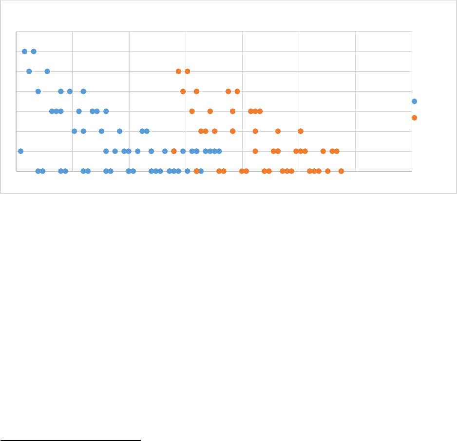
Figure 1-6 Example of a Defect Discovery for Incremental Development
The most important metric is the defect discovery trend. If the trend is not
decreasing, then most of the other metrics are largely irrelevant. The second most
important metric is the fix rate which ensures that the contractor is fixing the defects fast
enough to address the failures that effect reliability or availability. Also important are the
defects not piling up from release to release or Sprint to Sprint. Figure 1-6 is an
example of defect pileup. The discovered defects are plotted in increments of 10 usage
hours. When Sprint 2 was merged in at 190 hours, the most recent defect discovery rate
was at 1 defect per 10 hours. However, at 350 hours, the most recent rate is at 5 per
10 hours (4 from Sprint 2 and 1 from Sprint 1). Sprint 3 is about to be merged in despite
the increase in the rate and the fact that Sprint 2 received 30 hours less of testing than
0
2
4
6
8
0 50 100 150 200 250 300 350 400
on-
Cumulative unique defects
discovered
Usage in hours
Defects discovered
over usage time
Sprint 1
Sprint 2
Sprint 2
merged here
Sprint 3 will
be merged
here
APPROVED FOR PUBLIC RELEASE
24
Sprint 1. If Sprints 3 and beyond continue in this pattern, eventually the software will be
released with an increasing defect rate.
In the below Figure 1-7, the sprints are spaced far enough apart so that the defect
discovery rate is not increasing from sprint to sprint. At the start of sprint 2 the total
defects discovered per day peaks at 5 per day for sprint 2 plus 1 per day from sprint 1.
This isn’t worse than the peak defect discovery rate for sprint 1. Since the defects are
directly related to the amount of new code, sprint 2 was likely smaller in scope than
sprint 1. In order to deliver sprints of the same size as sprint 1, the sprints would need
to be spaced at 375 hours instead of 300 hours. At 375 usage hours is when there are
no more defects being found from sprint 1.
Figure 1-7 Example #2 of a Defect Discovery for Incremental Development
The below two (2) metrics are not relatively expensive and are generally required for
DevSecOps dashboards:
• The defect discovery fault rate (it should not be increasing)
• The fix rate should be keeping up with the discovered defects failures as per the
FDSC.
Stable programs having new software upgrades are at less risk than a brand-new
major program. This task is not terribly expensive as there are a variety of low
cost/open-source tools such as C-SFRAT
6
that trend the reliability as per the IEEE 1633
2016 clause 5.4.
If this is an MTA program, the reliability software evaluation will typically be one of
the most important tasks next to the testing for reliable software. MTA programs with no
transition to MCA can be specified to have only the fault and fix rates.
6
https://lfiondella.sites.umassd.edu/research/software-reliability/
0
1
2
3
4
5
6
7
0 100 200 300 400 500 600 700
Faults over usage time
Sprint 1
Sprint 2

APPROVED FOR PUBLIC RELEASE
25
1.5.2 Tailoring the SOW Language
Step 1: If the result of the decision tree in Figures 1-1 and 1-2 and/or Table 1-2 is
that software does not need to be included in the software reliability evaluation then do
not include the entire SOW language. Otherwise, the reliability engineer must tailor the
SOW language per the following steps:
Step 2: Modify the SOW language:
• Remove any bolded tasks from the SOW language that are deemed to
be not relevant as per the applicable decision tree.
• Remove the non applicable DID <DI-SESS-81628 or DI-SESS-80255>.
Step 3: The SOW language is:
“The contractor shall perform software Reliability Evaluation IAW IEEE 1633 2016
clauses 5.4.4, 5.4.5, 5.4.6, 6.3 and Annex C and shall identify: 1) justification for
selecting of reliability evaluation models; 2) provide the reliable software curves to the
Government; 3) trend of failure rate (increasing, peaking or decreasing); 4) evidence
that fix rate is addressing failures; 5) backlogged defects; 6) estimated defects, test
hours and test assets to achieve the specified/allocated reliability; 7) trend in severity of
discovered defects; 8) downtime (mean time to software restore). The contractor shall
deliver the reliability evaluation model(s), curve(s), and justification as part of the
Reliable Software Program Plan (RSPP) delivered in the R&M Program Plan (RPP) per
DI-SESS-81613.”
The reliability evaluation models shall be applied during contractor testing of each
build. The contractor shall include all software LRUs with the system in the reliability
agile/CI/CD framework. The contractor shall identify the test / usage hours per day or
week since software fails as a function of usage and not calendar time. The contractor
shall record the defects and corresponding failure modes found in the FRACAS system,
update the reliability models after each software build tests and update the system
reliability growth model. The contractor shall keep the models, tracking, and projections
up to date and be prepared to share any updates during working group meetings. The
contractor shall deliver reliability evaluation curves at the system level, and separately
for hardware and software. The reliability test results (models, tracking, and
projections) shall be delivered as per <DI-SESS-81628 or DI-SESS-80255.>”
1.5.3 Tailoring the CDRL
See Appendix C for the CDRL template. Steps for tailoring as follows:
Step 1: Do not create a separate CDRL for software reliability evaluation model(s),
curve(s), and justification(s). These should be delivered as part of the RSPP section of
the RPP DI-SESS-81613.

APPROVED FOR PUBLIC RELEASE
26
Step 2: All information related to due dates, frequency, and government approval
shown in Appendix C CDRLs are recommendations. The reliability engineer should
complete all blocks based on program-specific information.
• Initial delivery – The initial reliability evaluation should occur as soon as the first
developer test event concludes. If the Waterfall model is being used, then this
will be at the end of an external release cycle.
• Frequency of updates – If the contractor is employing Agile/CI/CD then the
testing is conducted iteratively. Sometimes testing sprints are very short in
duration so delivering a CDRL every test event will be expensive. Instead, the
contractor should make the reliability evaluations visible to the government
during test events by simply providing the government reliability engineer with the
failure data and times to failure to perform trend analysis
Step 3: Remove all shaded text within <>.
1.6 Software FMEA (SFMEA) Task
Software failure modes can originate in one of three ways:
• The specification - including Software Requirements Specifications (SRS),
Interface Requirements Specification (IRS) or design – is inherently faulty.
• The software specification is missing a crucially import detail or scenario.
• The code is not written exactly to the written specifications.
A common myth is only defects originating in the code are root cause failures as
opposed to the design or specifications being “failures.” Another common myth is that
failures due to systematic design faults don’t count. Another myth is that failures are
limited only to those that cause a shut down or termination. See the IEEE 1633
definitions in the appendix. As per the definitions, failure is defined by the effect with
regards to the specifications and not the underlying root cause. If the system fails
due to software, the cause does not matter if it was due to the implementation error or
the design / architecture error. The system still failed. The purpose of this task is to
focus on the failure modes due to the architecture, specifications, design, interfaces,
and code. Process related failure modes are those that pertain to flaws in
organizational structure and processes that allowed the defect to escape into operation.
A process FMEA is possible for software but is not the scope of this task or this
statement of work. The following sections provide the basis / justification for the task
and tailoring the SOW language to the Acquisition Strategy.
1.6.1 Basis / Justification
Since 1962, the same software failure modes have affected multiple missions
repeatedly. Below are a few examples of the failure modes:

APPROVED FOR PUBLIC RELEASE
27
• Faulty error handling – Quantas flight 72
7
un-commanded downward pitch
(incorrect fault recovery), Mars Polar Lander (software failed to detect spurious
data)
8
, Denver Airport (software assumed the luggage would not get jammed)
9
,
NASA Spirit Rover
10
(too many files on drive not detected)
• Faulty data definition – ESA Ariane 5 explosion (16/64-bit mismatch)
1112
, Mars
Climate Orbiter (Metric/English mismatch)
13
, TITANIV (wrong constant defined)
14
• Faulty logic/sequence – Solar Heliospheric Observatory spacecraft mishap
15
,
AT&T Mid Atlantic outage in 1991
16
, Operator’s choice of weapon release
overridden by software control
17
• Faulty state management – Incorrect missile firing from invalid setup
sequence
18
• Faulty algorithm – Flight controls fail at supersonic transition
19
, Mariner 1
20
mishap
• Faulty timing – 2003 Northeast blackout
21
, Therac 25 race condition
22
, Missile
launch timing error
23
, Apollo 11 lunar landing
24
• Faulty endurance – PATRIOT system failure
25
• Peak load conditions – IOWA caucus failure
26
• Faulty usability
• Software makes it too easy for humans to make irreversible mistakes –
Panama City, Panama over-radiation
27
• Insufficient positive feedback of safety and mission critical events
The SFMEA is beneficial when executing functions that cannot be reversed, have a
serious effect, cannot be avoided or overridden by humans and happen
instantaneously. Also, the SFMEA is beneficial when conducted against the design
and specifications as opposed to a source code line by line analysis. Historically,
greater than 50% of all software faults originate in the specifications or design
28
.
7
https://www.atsb.gov.au/publications/investigation_reports/2008/aair/ao-2008-070/
8
https://solarsystem.nasa.gov/system/internal_resources/details/original/3338_mpl_report_1.pdf
9
http://calleam.com/WTPF/wp-content/uploads/articles/DIABaggage.pdf
10
https://llis.nasa.gov/lesson/1483
11
https://www.nytimes.com/1996/12/01/magazine/little-bug-big-bang.html
12
https://www.esa.int/Newsroom/Press_Releases/Ariane_501_-_Presentation_of_Inquiry_Board_report
13
https://solarsystem.nasa.gov/missions/mars-climate-orbiter/in-depth/
14
https://www.faa.gov/regulations_policies/faa_regulations/commercial_space/media/Guide-Software-Comp-Sys-Safety-RLV-
Reentry.pdf
15
https://umbra.nascom.nasa.gov/soho/SOHO_final_report.html
16
https://telephoneworld.org/landline-telephone-history/the-crash-of-the-att-network-in-1990/
17
JOINT SOFTWARE SYSTEMS SAFETY ENGINEERING HANDBOOK, Appendix F Lessons Learned Section F.6.
18
JOINT SOFTWARE SYSTEMS SAFETY ENGINEERING HANDBOOK, Appendix F Lessons Learned Section F.5.
19
JOINT SOFTWARE SYSTEMS SAFETY ENGINEERING HANDBOOK, Appendix F Lessons Learned Section F.4.
20
https://nssdc.gsfc.nasa.gov/nmc/spacecraft/display.action?id=MARIN1
21
https://www.energy.gov/sites/prod/files/oeprod/DocumentsandMedia/BlackoutFinal-Web.pdf
22
JOINT SOFTWARE SYSTEMS SAFETY ENGINEERING HANDBOOK, Appendix F Lessons Learned Section F.1.
23
JOINT SOFTWARE SYSTEMS SAFETY ENGINEERING HANDBOOK, Appendix F Lessons Learned Section F.2
24
https://history.nasa.gov/computers/Ch2-6.html
25
JOINT SOFTWARE SYSTEMS SAFETY ENGINEERING HANDBOOK, Section E.3.15 Endurance Issues
26
https://www.cnbc.com/2020/02/04/iowa-caucus-app-debacle-is-one-of-the-most-stunning-it-failures-ever.html
27
https://www.fda.gov/radiation-emitting-products/alerts-and-notices/fda-statement-radiation-overexposures-panama
28
Neufelder, Ann Marie. “Cold Hard Truth About Reliable Software, Edition 6j, 2019”.

APPROVED FOR PUBLIC RELEASE
28
Analyzing the design and specifications ensures more coverage because the SFMEA
may identify failure modes that span across many lines of code.
A popular myth is software failures originate in a single line of code. While some
failures can be traced to exactly one line of code, most are the result of defects in
several lines of code or even several functions. Analyzing the lines of code results in
less coverage due to the effort required. This approach is implied as a best practice in
the SAE ARP-5580 standard, but should be avoided. Table 1-5 illustrates the points
of view or levels of analysis for the software FMEA that are recommended.
Method
Description
Functional
Focus on architecture and specifications and, in particular, unwritten
assumptions. Applied at 3 levels:
1. Functional Top Level (TL) – general requirements of the system.
For example, the PATRIOT system failure
29
was due to the
endurance. Endurance issues like this typically are not traceable to
any single feature or functional specification.
2. Functional Capability Level (CL) – general requirements specific to
use case, feature, or capability level (e.g. peak load related to single
use case).
3. Functional Specification Level (SL) – requirements of a single
software specification statement or user story. For example, the
NASA DART spacecraft required velocity accuracy of +/- 2m/s. The
numerical part of the requirement was wrong.
Interface
Focus on the interface design faults such as, conflicts with data type /
size/ format /scale / resolution / units of measure. For example, the
Mars Climate Orbiter crash
30
due to metric-English unit conflict.
Detailed
Focus on the code, is most labor intensive and cannot identify faults
due to “missing code.” For example, the software engineers of the
Denver Airport Luggage handler assumed that all luggage would be
perfectly placed onto the luggage belt. The software developer never
wrote code to manage this known and guaranteed scenario.
Table 1-5 Software FMEA points of view
The SFMEA must be completed prior to the code being finished and definitely prior
to the testing completion. Some approaches for completing the SFMEA in the faster
calendar time include but are not limited to analyzing:
• A checklist of top-level failure modes that have affected similar DoD weapons
• A narrow selection of the most critical software capability
• A wider selection of mission critical capabilities examined against one or two
failure modes such as faulty error handling (software cannot handle hardware
faults, power faults, network faults)
29
JOINT SOFTWARE SYSTEMS SAFETY ENGINEERING HANDBOOK, Section E.3.15 Endurance Issues
30
https://solarsystem.nasa.gov/missions/mars-climate-orbiter/in-depth/
APPROVED FOR PUBLIC RELEASE
29
• The critical interfaces or new interfaces or interfaces between multiple contracts
and contractors
• An alternative software fault tree – Conduct a fault tree of anything that can go
wrong with the software (this is typically less expensive than a SFMEA)
When calendar time is running short, one alternative is to select top level failure
modes that have wreaked havoc on major DoD systems (Appendix B TL Common
Defect Enumeration (CDE)). The following are CDEs applicable to most weapon
systems:
• Endurance – system degrades during life of mission – CDE TL-PR-1 and TL-PR-
2
• Peak loading – system cannot handle multiple threats at same time or different
threats CDE TL-PR-5 through TL-PR-8
• Processing – Videos, data logs, files build up over time and eventually cause
mission computers to shut down – CDE TL-PR-3
• Inability to detect or handle hardware faults, power faults, communication faults,
computations faults or user faults – CDE TL-EH-1 through CDE TL-EH-30
• Changes in mission such as duration – CDE TL-FC-4
• Prohibited state transition allowed by code – CDE TL-SM-1 and CDE TL-SM-2
• Software is unable to recover after an abort or unexpected shut down or loss of
power – CDE TL-SM-5
1.6.2 Tailoring the SOW Language
Step 1: If the result of the decision tree in Figures 1-1 and 1-2 and/or Table 1-2
indicates that this task is not relevant, then remove the SFMEA from the RSPP and the
SOW Otherwise, the reliability engineer must tailor the SOW language per the following
steps:
Step 2: The SFMEA SOW language consists of two paragraphs, first paragraph
defines the scope while the second paragraph ensures that the SFMEA is conducted by
the right people at the right time. Determine the program type and applicable section
IAW Table 1-6.
Step 3: Given the program type proceed to the applicable section for SOW
language as per the following subsections.

APPROVED FOR PUBLIC RELEASE
30
Program type
Applicable section
MCA
1.6.2.1
MTA program with no transition to MCA program
1.6.2.2
MTA program with rapid prototyping transition directly
to deployment
1.6.2.3
Air worthiness program which are required to conform
to SAE ARP 5580
1.6.2.4
Any program with change in mission time, weight, or
payload
Add the text in 1.6.2.5 to
one of the above sections
Table 1-6 Tailoring the SFMEA SOW language
1.6.2.1 MCA Program
The SFMEA may focus on the mission critical capabilities, specifications, and
interfaces with tailoring of these architectural levels, failure modes and root causes that
are most applicable for the type of system. The bolded text represents the default
approach. Visit the Defense Acquisition University (DAU) R&M Communities of
Practice (CoP) website (https://www.dau.edu/cop/rm-engineering/Pages/Default.aspx)
for update to the CDEs in Appendix B. Select or exclude the CDEs based on the
recommendations. Tailor SOW language as follows:
Step 1: Tailor <top level, capability level, specification level, interface level>.
Caution: The SAE ARP-5580 discusses detailed FMEAs. Detailed level failure modes
analysis is expensive, time consuming, and labor intensive and not recommended.
Delete any levels not selected. Unbold the text and remove the brackets.
Step 2: Tailor <Top-Level, Capability Level, Specification Level, and Interface
Common Defect Enumeration Table(s) or Select specific CDEs from DAU COP
Tables to narrow the scope >. Delete any levels not selected. Unbold the text and
remove the brackets or select specific CDEs to narrow the scope of the SFMEA.
Step 3: If the Specification Level is selected then the following text will remain,
<The contractor shall tailor the Specification Level Common Defect Enumerations
for software specifications that are new, mission critical, and weakly stated as per
the INCOSE Guide for Writing Software Requirements. > otherwise remove the
bracketed text.
Step 4: Tailor <and software fault tree analysis>. Remove software fault tree
analysis if not selected, otherwise unbold the text and remove the brackets.
Step 5: Visit section 1.6.2.5 and if applicable add in the CDEs related to changes in
mission, payload or hardware interfaces.
Step 6: Government reliability engineer coordinate with the Software Engineer to
tailor SOW language, since DIDs are controlled by the software engineering

APPROVED FOR PUBLIC RELEASE
31
organization: <The derived requirements shall be incorporated into the software
requirements, software design, software test and verification plans IAW DI-IPSC-
81433, DI-IPSC-81435, DI-IPSC-81438, and DI-IPSC-81439. >” Delete any DIDs with
corresponding language not selected. Unbold the text and remove the brackets.
SOW language as follows:
“The contractor shall identify, confirm, and mitigate the software failure modes
affecting mission critical functions. The contractor shall demonstrate understanding of
SW controls that do not depend on human interaction and link to mitigating mission
critical functions. The contractor shall analyze the <top level, capability level,
specification level, interface level> from the software functional FMEA viewpoint
employing the software centric failure modes in the <Top-Level, Capability Level,
Specification Level and Interface Common Defect Enumeration Tables or Select
specific CDEs from DAU COP Tables to narrow the scope > located on the Defense
Acquisition University (DAU) R&M Community of Practice (CoP) website
(https://www.dau.edu/cop/rm-engineering/Pages/Default.aspx). <The contractor shall
tailor the Specification Level Common Defect Enumerations for software
specifications that are new, mission critical, and weakly stated as per the INCOSE
Guide for Writing Software Requirements.> All mission modes shall be considered
in the analysis. The justification for the tailoring the CDE shall be documented. The
software FMEA (SFMEA) shall be prepared using the IEEE 1633 2016 clause 5.2.2 as a
guide.
The SFMEA < and software fault tree analysis> shall be conducted prior to the
completion of the software code with or by a cross functional effort between software
engineering, systems engineering and reliability engineering. At least one member of
the cross functional team understands software development. If agile/CI/CD framework
is employed, the SFMEA is conducted incrementally prior to the development of the
code and continuing throughout the lifecycle for the particular increment. Use IEEE
1633 2016 Table 10, as guidance. The contractor shall update the SFMEA during
development and test and make available to Government Working Groups. The
SFMEA shall be delivered in contractor format, an electronically searchable and
filterable, in the overall Failure Modes Effects Criticality Analysis report as per DI-SESS-
81495 except for column M, P, R, S, T, and U which do not apply to software failure
modes. In lieu of items T and U, the contractor shall assess likelihood of software
failure modes based on detectability of the specific software failure mode/root cause in
development and test. The contractor shall derive software requirements for
identification and recovery of uncontrolled mission critical failure modes identified in the
SFMEA. The contractor shall define fault tolerance for mission critical SW and link to
SRS requirement/user story and verify fault tolerance, controls, and mitigations via fault
injection testing. <The derived requirements shall be incorporated into the
software requirements, software design, software test and verification plans IAW
DI-IPSC-81433, DI-IPSC-81435, DI-IPSC-81438, and DI-IPSC-81439. >”
APPROVED FOR PUBLIC RELEASE
32
1.6.2.2 MTA Program with no transition to MCA
If this is an MTA program with no transition to MCA, then the SFMEA should focus
on the top-level failure modes. The reliability engineer might also define which modes
to focus on to narrow the focus even further. One option is to cover the mission critical
modes that are not be covered by a software safety assessment. Tailor SOW language
as follows:
Step 1: Follow the instructions in section 1.6.2.1. Remove all viewpoints except for
the top level.
Step 2: If possible, identify specific top level CDEs to reduce the cost and time even
further as per section 1.6.2.1.
Step 3: Visit section 1.6.2.5 and if applicable add in the CDEs related to changes in
mission, payload or hardware interfaces.
1.6.2.3 MTA Program with Rapid Prototyping Transition Directly to Deployment
For an MTA program with Rapid Prototyping transitioning directly to field
deployment, the government reliability engineer must evaluate the available time and
cost for the SFMEA. Testing for reliable software and reliability evaluation will be the
most important tasks. If the SFMEA is chosen, a top-level SFMEA or very tailored to a
specific hazard (see SOW language in section 1.6.2.2) would be appropriate.
Alternatively, the SFMEA can be substituted with the fault trees which can be completed
in shorter calendar time. The CDE table is reviewed and those CDEs that pertain to the
mission critical function are listed.
Software fault tree analysis (FTA) is useful for preparing for the SFMEA and should
be performed in conjunction with a hardware FTA. Software FTA is conducted from the
opposite viewpoint of the SFMEA. The software FTA can identify failure modes using a
top down as opposed to bottom-up viewpoint. The software FTA is often conducted
prior to a SFMEA to identify the hazards and most likely root causes. The SFMEA then
explores those root causes and may identify additional hazards not uncovered by the
software FTA. The software FTA is typically less labor intensive than a SFMEA. Tailor
SOW language as follows:
Step 1. Decide whether to substitute the SFMEA with the software fault tree. The
software fault tree is most effective when there is a hardware fault tree. If there is no
hardware fault tree specified then the SFMEA with only the top level failure modes is a
better option. If the SFMEA is selected then refer to section 1.6.2.2. Otherwise
proceed to step 2.
Step 2: Select relevant CDEs <List any relevant CDEs here that pertain to the
features>. Unbold the text and remove the brackets

APPROVED FOR PUBLIC RELEASE
33
Step 3: Visit section 1.6.2.5 and if applicable add in the CDEs related to changes in
mission, payload or hardware interfaces.
Step 4: Government reliability engineer coordinate with the Software Engineer to
tailor SOW language, since DIDs are controlled by the software engineering
organization: < The software fault and failure management requirements shall be
incorporated into the software requirements, software design, software test and
verification plans IAW DI-IPSC-81433, DI-IPSC-81435, DI-IPSC-81438, and DI-IPSC-
81439.> Delete any DIDs with corresponding language not selected. Unbold the text
and remove the brackets.
The SOW language as follows:
“The contractor shall define mission critical SW and link to the SRS requirements or
user stories to mission critical hazards here. Each mission critical SRS/user story shall
be verified during build test. The contractor shall identify, confirm, and mitigate the
software failure modes affecting mission critical hazards. The contractor shall
demonstrate understanding of SW controls that do not depend on human interaction
and that link to mitigating mission critical functions. The contractor shall consider, at a
minimum, <List any relevant CDEs here that pertain to the features> from the
Common Defect Enumeration table located on the Defense Acquisition University
(DAU) R&M Community of Practice (CoP) website (https://www.dau.edu/cop/rm-
engineering/Pages/Default.aspx).. The software fault tree analysis (SFTA) shall be
prepared using the IEEE 1633 2016 clause 5.2.3 as a guide.
“The SFTA shall be conducted prior to the completion of the software code by a
cross functional effort consisting of software engineering, systems engineering and
reliability engineering. The contractor shall update the SFTA during development and
test and make available to Government Working Groups. If Agile/CI/CD framework
employed the analysis is conducted incrementally prior to the development of the code
as per the IEEE 1633 2016 Table 10 and clause 5.2.3, as guidance, and continuing
throughout the lifecycle for the particular increment. The interim results of the SFTA
shall provide inputs for the software test plan and FRACAS. The contractor shall
illustrate tracing of failure modes to specific test cases. The contractor shall derive
software requirements for identification and recovery of mission critical hazards for
uncontrolled mission critical failure modes identified in the SFTA and shall ensure that
those derived software requirements are tested. The contractor shall define fault
tolerance for mission critical SW and link to SRS requirement / user story and verify
fault tolerance, controls, and mitigations via fault injection testing. The contractor shall
avoid “one size fits all” fault handling by determining the most appropriate means on an
individual fault by fault basis. The SFTA shall be delivered in contractor format, an
electronically searchable and filterable, in the overall FTA report as per DI-MISC-
80711A. <The software fault and failure management requirements shall be
incorporated into the software requirements, software design, software test and
verification plans IAW DI-IPSC-81433, DI-IPSC-81435, DI-IPSC-81438, and DI-IPSC-
81439.>”

APPROVED FOR PUBLIC RELEASE
34
1.6.2.4 A program required to conform to SAE ARP 5580
Some programs, such as air worthiness programs, may be required to conform to
SAE ARP 5580. Tailor SOW language as follows:
Step 1: Tailor <top level, capability level, specification level, interface level,
detailed level>. Caution: Detailed level failure modes analysis is expensive, time
consuming, and labor intensive and not recommended. Delete any levels not selected.
Unbold the text and remove the brackets.
Step 2: Tailor <Top-Level, Capability Level, Specification Level, and Interface
Common Defect Enumeration Table(s) or Select specific CDEs from DAU COP
Tables to narrow the scope >. Delete any levels not selected. Unbold the text and
remove the brackets or select specific CDEs to narrow the scope of the SFMEA.
Step 3: If the Specification Level is selected then the following text will remain,
<The contractor shall tailor the Specification Level Common Defect Enumerations
for software specifications that are new, mission critical, and weakly stated as per
the INCOSE Guide for Writing Software Requirements. > otherwise remove the
bracketed text.
Step 4: Tailor <and software fault tree analysis>. Remove software fault tree
analysis if not selected, otherwise unbold the text and remove the brackets.
Step 5: Visit section 1.6.2.5 and if applicable add in the CDEs related to changes in
mission, payload or hardware interfaces.
Step 6: Government reliability engineer coordinate with the Software Engineer to
tailor SOW language, since DIDs are controlled by the software engineering
organization: <The derived requirements shall be incorporated into the software
requirements, software design, software test and verification plans IAW DI-IPSC-
81433, DI-IPSC-81435, DI-IPSC-81438, and DI-IPSC-81439. >” Delete any DIDs with
corresponding language not selected. Unbold the text and remove the brackets.
The SOW language as follows:
“The contractor shall identify, confirm, and mitigate the software failure modes
affecting mission critical functions. The contractor shall demonstrate understanding of
SW controls that do not depend on human interaction and link to mitigating mission
critical functions. The contractor shall analyze the <top level, capability level,
specification level, interface level, and detailed level failure modes> from the
software functional FMEA viewpoint employing the software centric failure modes in the
<Top-Level, Capability Level, Specification Level and Interface Common Defect
Enumeration Tables or Select specific CDEs from DAU COP Tables to narrow the
scope > located on the located on the Defense Acquisition University (DAU) R&M
Community of Practice (CoP) website (https://www.dau.edu/cop/rm-
engineering/Pages/Default.aspx). <The contractor shall tailor the Specification
APPROVED FOR PUBLIC RELEASE
35
Level Common Defect Enumerations for software specifications that are new,
mission critical, and weakly stated as per the INCOSE Guide for Writing Software
Requirements.> All mission modes shall be considered in the analysis. The
justification for the tailoring the CDE shall be documented. The SFMEA shall be
prepared using the SAE ARP-5580 as a guide, except for sections 6.1.2 and 6.4 which
do not apply to software failure modes. In lieu of paragraph 6.4, the contractor shall
assess likelihood of software failure modes based on detectability of the specific
software failure mode/root cause in development and test. The failure modes identified
in the CDE tables shall be considered in lieu of section 6.1.
The SFMEA < and software fault tree analysis> shall be conducted prior to the
completion of the software code with or by a cross functional effort between software
engineering, systems engineering and reliability engineering. At least one member of
the cross functional team understands software development. If agile/CI/CD framework
is employed, the SFMEA is conducted incrementally prior to the development of the
code and continuing throughout the lifecycle for the particular increment. Use IEEE
1633 2016 Table 10, as guidance. The contractor shall update the SFMEA during
development and test and make available to Government Working Groups. The final
SFMEA shall be delivered in contractor format, an electronically searchable and
filterable, in the overall Failure Modes Effects Criticality Analysis report as per DI-SESS-
81495 except for columns M, P, R, S, T, and U which do not apply to software failure
modes. In lieu of items T and U, the contractor shall assess likelihood of software
failure modes based on detectability of the specific software failure mode/root cause in
development and test. The contractor shall derive software requirements for
identification and recovery of uncontrolled mission critical failure modes identified in the
SFMEA. The contractor shall define fault tolerance for mission critical SW and link to
SRS requirement/user story and verify fault tolerance, controls, and mitigations via fault
injection testing. <The derived requirements shall be incorporated into the
software requirements, software design, software test and verification plans IAW
DI-IPSC-81433, DI-IPSC-81435, DI-IPSC-81438, and DI-IPSC-81439. >”
1.6.2.5 Any program with a change in mission time, weight, or payload
If this program scope requires a change in either mission time, payload, or hardware
interface then the below bolded text should be added to the SOW to ensure that the
SFMEA focuses on the key risk areas. Note that this type of SFMEA is applicable even
if the software organization thinks that the software is unaffected. The below text can be
merged into SOW language from other sections such as the airworthiness language or
the MCA program language or the MTA program language.
“The contractor shall analyze all of the failure modes and root causes associated
with TL-FC-4, SL-FC-12, SL-FC-13 and SL-FC-14 from the Top-Level Common Defect
Enumeration table.”

APPROVED FOR PUBLIC RELEASE
36
1.6.3 Tailoring the CDRL
See Appendix C for the CDRL template. Steps for tailoring as follows:
Step: 1: Do not create a separate CDRL for software. Insert language for both the
SFMEA/FMECA in Failure Modes Effects Criticality Analysis report as per DI-SESS-
81495.
Step: 2: All information related to due dates, frequency, and government approval
shown in Appendix C CDRLs are recommendations. The reliability engineer should
complete all blocks based on program-specific information.
• Initial delivery – The contractor should provide a preliminary SFMEA that has the
failure modes and root causes identified and ranked and stacked by severity and
controls. The CDRL should identify a preliminary SFMEA to be delivered for
MCA [90 DAC (TMRR) / 30 DAC (EMD)] TMRR and MTA (90 DAC).
• Frequency of updates – The SFMEA is most effective when it is conducted
immediately after the software requirements are baselined but before all the code
is developed and tested for that set of requirements. If the requirements are
developed incrementally, the SFMEA can and should be conducted
incrementally. The intent of the SFMEA is to identify and mitigate the failure
modes that are typically either expensive to fix if found in testing or highly likely to
escape the testing process. After the initial delivery, final SFMEA has the failure
mode/root cause pairs that have the highest severity and least controls mitigated
or tested out. The contractor should keep the SFMEA up to date throughout
development and be prepared to share these SFMEA in working group meetings.
However, the formal deliveries are made at major milestones.
Step 3: Remove all shaded text within <>.
1.7 Inclusion of Software in FRACAS Task
The contractor is required to have a closed loop process for software failure reports.
This task is simply making those reports available to the Government and tagging the
failures that effect reliability.
This task is needed in the SOW because the
contractor will often not provide these reports unless contractual language that
specifically calls out software problem reports is included in the SOW.
All
software failure reports must be delivered in a format friendly to automation. A format in
conformance with some standard is required to ensure semantic interoperability with
tools the government has, or can script to analyze the failure report, make forecasts,
provide dashboards, etc. The following sections provide the basis / justification for the
task and tailoring the SOW language to the Acquisition Strategy.
1.7.1 Basis / Justification
Reliable Software is often disregarded / under resourced / inadequate mission
reliability testing resulting in failure to achieve mission reliability.

APPROVED FOR PUBLIC RELEASE
37
The contractor must have a FRACAS to be minimally able to manage the program
therefore, providing DoD access to FRACAS data should not be cost prohibitive. This
task applies to software projects, such as, Incremental, Agile, Waterfall or Spiral.
Integrated FRACAS provides the ability to collect trends and implement corrective
actions to ensure mission reliability and maintainability. The developmental framework
determines the frequency that the data is provided to the DoD. The contractor must not
have duplication of effort with multiple problem reporting systems. Instead, the mission
reliability related software failures should be tagged appropriately, (as reliability related)
and made available to the Government via export.
For agile/CI/CD frameworks, the FRACAS shall be continuous updated as the
system grows from a Minimum Viable Product (MVP) and continues until end of the
contract. The reliability engineer should monitor contractor FRACAS at start of MVP,
initial/baseline software build, or initial software release under configuration control.
1.7.2 Tailoring the SOW Language
No tailoring is required. SOW language as follows:
“The Contractor shall tag all software failure reports from the start of Minimum Viable
Product, initial / baseline software build, or initial software release under configuration
control. The failure reports shall capture the failure effects and severity. The failures
shall be captured in an automated system. The contractor should show evidence (via
regression testing) that corrective actions did not cause any adverse effect on the rest
of the SW. The contractor shall prioritize fixing of the root cause of the software failure
and software maturity. The contractor shall participate and be prepared to share any
FRACAS updates during the government working group meetings per the program
integrated master schedule. The contractor shall deliver the FRACAS report IAW DI-
SESS-80255 (CDRL AXX).”
1.7.3 Tailoring the CDRL
See Appendix C for the CDRL template. Steps for tailoring as follows:
Step 1: Do not create a separate CDRL for software. Insert language for both the
hardware and software FRACAS in DI-SESS-80255.
Step 2: All information related to due dates, frequency, and government approval
shown in Appendix C CDRLs are recommendations. The reliability engineer should
complete all blocks based on program-specific information.
Step 3: Remove all shaded text within <>.

APPROVED FOR PUBLIC RELEASE
38
1.8 Software Reliability Risk Assessment Task
The SFMEA and software fault tree identify specific functional failure modes that
directly lead to a specific system failure. Software risks are organizational decisions
that can lead to many software failures. Whenever software is seriously late, the
software will also be seriously faulty. One or two bad decisions or unmitigated risks can
derail the entire program. Historically, these risks were known from the start of the
program but no one paid attention to them or understood their effect on the program.
One notorious example of a reliable software risk was with the Denver Airport
upgrade
31
. This project, which cost $560 million in the 1990s, was intended to fully
automate the luggage handling at three (3) concourses in the Denver airport. The
project was doomed from the first day because:
• The scope of the work was significantly underestimated by the contractor and the
airport.
• The contractor ignored numerous warnings from people who developed similar
systems that their plan was impossible in the timeframe quoted.
• The software team ignored advice from experts who understand how airport
systems work.
• The software engineers did not understand or work towards the goal - which is to
reduce aircraft turnaround time.
• The software solution was never coordinated with the plans for the airport.
• The contractor accepting change requests even though the original plan was
already impossible to meet.
• No contingency or backup plans
• Schedule decisions were agreed to by people who did not understand what it
takes to develop software.
The software was two (2) years late and was significantly reduced in scope. The
reduced solution required significant manual work from the airport staff and was
eventually scrapped because the automation cost the airport more than having no
automation. This example is from the commercial world but the risks and lessons
learned applies to every DoD program. These are some of the risks that can single
handedly derail a program:
• Grossly underestimating the complexity of the problem to be solved. This is most
likely the first time a contractor has developed a system like this.
• The contractor has a team of software engineers that does not understand the
mission, weapon, customer, or industry.
• Grossly underestimated the work required to modify the code for a new mission
duration or mission type or new weapon hardware.
• The contractor has software people who are not near or integrated with the target
hardware or hardware engineers
31
http://calleam.com/WTPF/wp-content/uploads/articles/DIABaggage.pdf

APPROVED FOR PUBLIC RELEASE
39
• The contractor is attempting to handle too many learning curves in a single
customer release.
• The contractor has no contingency plans.
• The schedule is determined by people who are not knowledgeable about
software development.
• The contractor plans to reuse code that is not reusable.
• The contractor is not planning to reuse code when the contractor should.
• Learning curves include but are not limited to:
• New technology to the software team (e.g., the first time the contractor
has developed a cloud application).
• Hardware interfaces that are undefined and evolving
• A sudden change in staff or company leadership.
These are the lessons learned when this task is not included in the SOW:
• Too many learning curves for the software engineers leads to underestimates of
effort.
• When effort is underestimated, the schedule may slip by a non-trivial amount
then reliability suffers.
The following sections provide the basis / justification for the task and tailoring the
SOW language to the Acquisition Strategy.
1.8.1 Basis / Justification
This task is effective given the following:
• The system is new system or introduces new technology or undergoing a major
upgrade.
• The system includes a relatively large software program – million lines of code or
more (check with the software engineering counterpart to gauge the size and
complexity of the proposed software).
• Some software reuse is expected.
• The software is being developed by more than one company.
• There is any technology involved that has never been used before.
This task is not expensive and can avoid faulty decisions made early the program
that are difficult / time consuming / expensive to undo later in the program. The
development framework does not have much of an effect on this task. Every risk can
apply whether there is agile development or waterfall development.
1.8.2 Tailoring the SOW Language
Step 1: If the result of the decision tree in Figures 1-1 and 1-2 and/or Table 1-2 is
that this task is not relevant, then remove this task from the RSPP and do not include
the entire SOW language. Otherwise, the reliability engineer must tailor the SOW
language per the following steps:

APPROVED FOR PUBLIC RELEASE
40
Step 2: Modify the SOW language by identifying risk that is not included in the IEEE
1633 2016 clause 5.1. Additional risks that might affect the program then replace
<include any other risks here not captured in clause 5.1.3> or remove text if no
additional risk are identified.
SOW language as follows:
“All risks identified in clause 5.1.3 and Figure 16 of the IEEE 1633 2016 <include
any other risks here not captured in clause 5.1.3> shall be identified, managed, and
mitigated. The contractor shall manage these risks and make plans for mitigating these
risks available to the Government. The contractor shall update the risk assessment
during development and test and make available to Government Working Groups. The
identified risks and plans for mitigating shall be delivered, in the software portion of the
RAM Program Plan IAW DI-SESS-81613.”
1.8.3 Tailoring the CDRL
See Appendix C for the CDRL template. Steps for tailoring as follows:
Step 1: Do not create a separate CDRL for software. Insert language for reliable
software risk assessment in the RSPP as part of the R&M Program Plan, DI-SESS-
81613.
Step 2: All information related to due dates, frequency, and government approval
shown in Appendix C CDRLs are recommendations. The reliability engineer should
complete all blocks based on program-specific information.
Step 3: Coordinate with the software engineering counterpart and ensure that the
reliability engineer’s office symbol is placed into block 14 of the SDP CDRL. The DID
for the SDP is DI-IPSC-81427. The software related risks can change if the software
scope changes or there is a new subcontractor/vendor/COTS component. This risk
assessment should be delivered at the same time as the SDP. Coordinate with the
software engineering counterpart so that this deliverable coincides with the SDP.
Step 4: Remove any shaded text within <>
1.9 Testing for Reliable Software Task
During testing, the contractor will generally test each of the software requirements to
demonstrate 100% requirements coverage. However, 100% coverage of software
requirements does not guarantee that all the code has been tested and the nominal and
off nominal cases are covered. In general, approximately 30-50% of the lines of code
are executed with requirements testing. Therefore, additional test coverage is required
to exercise the remaining nominal and off nominal conditions. Some methods for
increasing coverage include:
• Boundary value testing ensures that the edges of the data values and logic work
as well as the extreme data values such as exceptionally large and small values.

APPROVED FOR PUBLIC RELEASE
41
• Trajectory testing ensures that changing of data over time is handled.
• Go-no go testing ensures that the software satisfies both the true and false
outcomes. Go-no go testing verifies that the requirement isn’t executed unless
the conditions are met.
• Zero value testing ensures that the numbers close to zero do not cause an
overflow.
• Fault injection testing ensures that the software detects and recovers from
hardware, communication, computation, I/O, user faults, etc.
• Power testing ensures that when there is a power outage that the software /
weapon is safe upon startup.
• State testing verifies that states are not dead or orphaned and that transitions are
made only under the required conditions.
• Timing testing verifies that the software does it required job at the right time – not
too early and not too late.
• Data – tests diverse types and formats of data – i.e... Integers, fractions, strings,
etc.
The Venn diagram in Figure 1-8 shows all things that can be tested for software. If
the entire diagram is covered, then all lines of code, paths, and inputs are also covered.
Requirements testing is conducted against the written software requirements. If
conducted properly these tests can dramatically increase coverage and minimize
failures at both the nominal and the “edge cases.”
Figure 1-8 Venn diagram of Coverage via Various Test Methods
Example: The software is performing a driverless vehicle function. Table 1-7 shows
an example illustrates system level tests. While this example is from a vehicle level,
each of these tests can also be applied at a software function level. It may appear to be
many test cases but the tests can be combined to satisfy multiple objectives. The below
tests reduce to only twenty unique scenarios because the endurance, peak loading,

APPROVED FOR PUBLIC RELEASE
42
requirements, data value, zero value, timing and trajectory tests can be combined with
the other test cases.
The following sections provide the basis / justification for the task and tailoring the
SOW language to the Acquisition Strategy. The lessons learned is that when the
software isn’t tested for reliability that the DoD finds defects in operation that cost time
and dollars.
Test type
Software functional level example
System functional level example
TLYO
Drive like real people drive (teenagers, adults, working people, retired people, professional
drivers, etc.)
Trajectory
Using the same algorithm- it can range
from 50 to 90. Trajectory tests might
include starting at 50 and transitioning
to 90 and vice versa. Starting at 75
and transitioning to 50. Starting at 75
and transitioning to 90. Many others.
The vehicle is accelerated and deaccelerated from
each of these velocities to every other velocity – 1)
Very low speeds (school bus scenario), 2) low speed
(side streets), 3) medium speed (major roads), and 4)
high speed (highways)
Go-no go
The BIT software is required to
execute after 100ms. The no-go test
is that it does not start before 100ms.
The car does not brake when not commanded, does
not accelerate when not commanded, the convertible
top is not put down when not commanded
Fault
injection
tests
Injecting bad data such as NaN (not a
number)
Fault injection with faulty vehicle hardware or
consumables (brakes, oil, fluids, tires, etc.)
Power test
Cutting the power while running any
software intensive function.
Run out of gas and verify that the vehicle does not
accelerate or shift into reverse immediately after
refueling (i.e., should not remember what it was doing
before running out of gas).
State tests
Testing the lower-level state
transitions for all software functions.
Showing all low-level prohibited state
transitions are not allowed by the
software.
The vehicle does not transition to park mode while
driving or transition to drive mode while parking; or
the convertible top is not allowed to go up or down
while moving (whether commanded or not).
Timing
The BIT test starts no later than
100ms after startup and finishes no
later than 2 seconds
The car can brake or change lanes within the time
required
Endurance
test
Test each software function for the
maximum mission time for that
function
Get on a major highway and drive until nearly out of
fuel
Peak
loading
tests
Testing each function with the
maximum volume of concurrent inputs
Rapid succession of stop and go (traffic lights or
school bus)
Boundary
The algorithm accepts values between
50 and 90. The boundary tests are
49, 50, 90, and 91.
The vehicle is accelerated from stop, and from
maximum speed limit
Zero value
test
Setting values in computations to zero
or near zero.
Verify transitioning to stop (zero velocity) from all four
(4) velocity ranges and transitioning from stop to all
four (4) velocity ranges
Data value
tests
Using the algorithm example for
boundary testing – testing large jumps
in values, small jumps in values,
fractional changes in values.
Small velocity changes (going a few MPH faster or
slower), velocity changes in whole numbers, velocity
changes in fractional numbers, big velocity changes
(i.e., from 40 to 70mph or 70 to 40)
Table 1-7 Reliable Software Testing Examples
1.9.1 Basis / Justification
APPROVED FOR PUBLIC RELEASE
43
Testing every line of code or branch in logic can be relatively expensive mainly
because of the tools and effort that are required to prove the coverage. However, if
conducted properly, the tests discussed in this SOW language can cover the code. This
task can and should be tailored for the particular mission critical functions / LRUs.
Ideally the SOW is applied to those software functions that can cause a mission failure
and is not otherwise covered by testing requirements for air worthiness or software
safety.
This task identifies “what” types of tests to be run. The development framework has
no bearing on “what” is tested. This task is very relevant for software developed in an
agile framework. “When” the program expects conduct software test should be
identified in the program master schedule. The software delivery schedule shows when
software is being tested but not necessarily when these specific types of tests will be
tested. The important thing is tests are run prior the first deployed version for
government testing.
1.9.2 Tailoring the SOW Language
If the decision tree in Figures 1-1 or 1-2 or Table 1-2 indicates that this task is not
relevant, then remove this task from the RSPP and the SOW. Otherwise proceed to
these 6 steps:
Step 1: Identify which functions will need the reliability testing.
a. Determine if the software is required to conform to DO-178C. Aircraft
operating in controlled airspace and are required to comply with DO-178C
might be applying this task; but only for the safety significant software such as
the flight control system. DO-178C requires a certain level of coverage which
can be accomplished via the tests shown in Table 1-9. The mission critical
code may or may not be required to conform to DO-178C depending on the
Design Assurance Level.
• Coordinate with software engineering, software safety, and software
airworthiness to identify the level of rigor required above DO-178C for
each of the software functions to meet the reliability requirements.
• Ensure that software partitioning is used to isolate faults in a
system. For example, a fault in built-in test processing should be isolated
from flight control software.
• The reliability engineer should levy this task only on the software that is
tagged to specific mission hazards or specific mission critical features that
are not otherwise covered by the safety requirements.
• The reliability engineer should ensure that reliability is on distribution for all
software related testing.
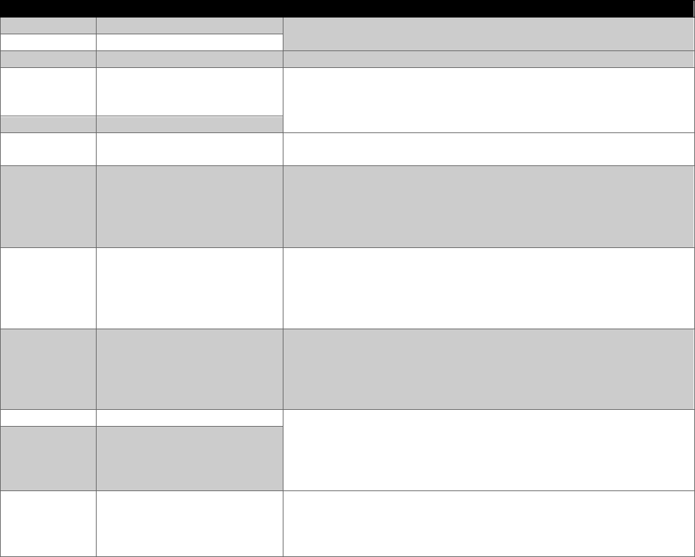
APPROVED FOR PUBLIC RELEASE
44
b. Determine if the software is required to conform with the Joint System Safety
Engineering Handbook (JSSSEH). Safety significant software for weapon
systems may be required to conform to the JSSSEH. The definition of “safety
significant” is defined by the program and safety panel.
• Coordinate with software engineering, software safety, and software
airworthiness to identify the level of rigor required for the JSSSEH for each
of the software functions to meet the reliability requirements.
• The reliability engineer should levy only on the software that is tagged to
specific mission hazards or specific mission critical features that are not
otherwise covered by the safety requirements.
• The reliability engineer should ensure that reliability is on distribution for all
software related testing.
Step 2: Identify which tests are needed. Use the below chart as a guide and listed
in priority for most weapon systems.
Test type
Applicability
Justification
TLYO
Applicable to all systems.
TLYO is the closest test to end user operation. The trajectory
tests are an important ingredient of TLYO.
Trajectory
Applicable to all systems.
Go-no go
Applicable to all systems.
Can be easily combined with requirements testing.
Fault
injection
tests
Applicable to all systems.
Can be covered at same time as a hardware fault injection test
if the required behavior of the software under various faulted
conditions is documented.
Power testing is a subset of fault injection testing.
Power test
Applicable to all systems.
State tests
Applicable to all systems.
This test ensures no inadvertent irreversible weapon events. It
is not expensive to test.
Timing
Applicable to all systems.
Timing is critical for weapons. If the software specifications
cover timing budgets this will be implicitly tested in the
requirements testing. However, tests for interrupt scheduling
analysis are typically not covered in the contractor’s
requirements testing.
Endurance
test
Applicable to all systems.
Most relevant for systems
that are on for an extended
duration (more than a few
hours).
This consists of one test for the duration of the mission time
without reboot. If the mission time is particularly long
benchmarking of timing and accuracy can establish whether the
software degrades for the entire mission.
Peak
loading
tests
Applicable to systems that
have multiple users,
multiple simultaneous
threats, multiple
workstations, etc.
This test is not expensive to run. Most of the work is in the
setup of the workstations, users, etc.
Boundary
Applicable to all systems.
Zero values and boundary tests are conducted at the same
time. These tests cost effectively verify ranges of value so as
to test the values that are most likely to be problematic. These
tests are not expensive, particularly when conducted at an LRU
level.
Zero value
test
Applicable to all systems.
Data value
tests
Applicable to all systems.
Data value tests are combined with other tests such as
boundary, zero value and trajectory tests to minimize the total
test cases. The goal is simply to test with varying data types
and sizes.
Table 1-8 Justification and Applicability for Reliable Software Tests
APPROVED FOR PUBLIC RELEASE
45
Step 3: Tailor <TLYO, trajectory, fault injection, power, state, timing,
endurance, peak loading, boundary, zero value and data value >. Delete the tests
that aren’t applicable for the system or are covered elsewhere in the SOW for the
mission critical functions. Delete the “<>” and unbold the font.
Step 4: The reliability engineer coordinates with the software engineering
organization as the outputs of this task reside in the software test plans, procedures and
results. The reliability engineer must work with software engineering personnel to craft
a SOW that balances reliability with other performance criteria such as safety.
SOW language as follows:
“The contractor shall develop software requirements for <TLYO, trajectory, fault
injection, power, state, timing, endurance, peak loading, boundary, zero value and
data value >. and conduct contractor development and operational tests on mission
critical software tagged to mission hazards to ensure reliable software.”
Note: The Government reliability engineer should coordinate with the Government
software engineering organization to ensure the SOW address language similar to the
following: 1) The contractor shall update and maintain a Software Test Plan (STP) IAW
DI-IPSC-81438, for each software external release which defines the plan, for new or
modified SW, to fully exercise the software as discussed above; 2) The contractor shall
develop Software Test Descriptions (STD) IAW DI-IPSC-81439 for each software
external release IAW the approved STP; and 3) The contractor shall perform all
software test activities IAW the SRM and the approved STP and develop and deliver
Software Test Reports (STR) IAW DI-IPSC-81440 for each external software release.
1.9.3 Tailoring the CDRLs
See Appendix C for the CDRL template. Reliability software testing requirements
should not have a separate CDRL requirement from the software engineering
organization. The reliability engineer coordinates with the software engineering
Government counterpart to ensure that the reliability engineer’s office symbol is placed
into the block 14 side of the CDRL/DID below. This ensures that test reports are
delivered to the reliability engineer. Once the documents are received, the reliability
engineer will review the documents to determine if the test planning and procedures will
cover any of the tests in Table 1-7. The reliability engineer will also verify that the
software procedures cover demonstration of the reliability allocation for the software as
per the SOW requirements discussed in section 1.3.
a. Software Test Plan (STP), DI-IPSC-81438
b. Software Test Description (STD), DI-IPSC-81439
c. Software Test Report (STR), DI-IPSC-81440
APPROVED FOR PUBLIC RELEASE
46
2.0 Customer and Contract Reliability Requirement
Two things must be considered for specifying the customer and contractual
reliability requirement. First, there must be an Failure Definition Scoring Criteria (FDSC)
defined by the customer. Second, the customer should be defining the objectives for
the whole system.
Below are some of the reasons for an FDSC:
• Failure criticalities outlined by Mil-STD 882E provides the top-level hazard
categories but does not provide a mapping from a specific software failure rate to
one of these categories. A FDSC is needed to objectively evaluate failure
criticalities.
• The same medium priority software fault occurs multiple times can have a
catastrophic effect.
• The same fault can have a different severity depending on the mode and context.
• Software that takes too long or requires too many manual steps or is too tedious
to use can be hazardous.
• Critical for Materiel Developer Reliability Engineer and User Community develop
a FDSC for the program prior to TMRR and updated as the program and
requirements mature. For MTA programs the FDSC should be started
immediately after contract and updated regularly.
Reliability specifications for system reliability such as system MTBEFF, can be
established by DoD but allocating appropriate portion to the software has to be done by
contractor. This is because the allocation to hardware and software is dependent on
how much software/hardware is in the design. The DoD should identify a system
reliability objective and require the contractor to allocate to hardware and software. The
contractor must know the DoD considers software as part of the system for
reliable purposes.
3.0 Section L
The below is example language that applies to all RAM tasks. Software has been
integrated into the language. If a particular paragraph does not apply to software, then
there is no mention of software in the paragraph.
Bold - addition to existing language to include software
R&M Program Strategy: The proposal shall describe the offeror's R&M processes,
tools, procedures, practices, and schedules for the integration of R&M engineering into
the system engineering process and the roles and responsibilities of R&M engineers in
design, fabrication, and testing of the system. This shall include the integration of
software.
APPROVED FOR PUBLIC RELEASE
47
4.0 Section M
In section M it needs to be clear that software is a key consideration in the proposal.
The below bolded text may be added to existing language.
1. Proven design – the proposed system or subsystems have been built, tested, and
documented to meet the proposed R&M requirements.
2. Proven concept – the proposed concept has been demonstrated and
documented to meet the proposed R&M requirements.
3. Documented plan for achieving the following objectives:
• R&M is incorporated into all aspects of the system engineering design
including hardware and software
• The design includes specific features which enhance ease of performing
maintenance
• The R&M requirements contained within the offeror’s proposal are achieved
and verified throughout the performance of R&M design analyses and test
activities including hardware and software
4. Documented understanding of R&M requirements and plans for the
management, design, monitoring, testing, and verification efforts for both hardware
and software.

APPROVED FOR PUBLIC RELEASE
48
Appendix A DoD Acquisition Pathways
Figure A-1 shows the six DoD acquisition pathways
32
. This SOW guidance is only
for MCA, MTA, and Software Acquisition.
Figure A-1: DoD Acquisition Pathways
Figure A-2: Flow of the MTA Paths
32
DoDI 5000.02, “Operation of the Adaptive Acquisition Framework,” January 23, 2020)
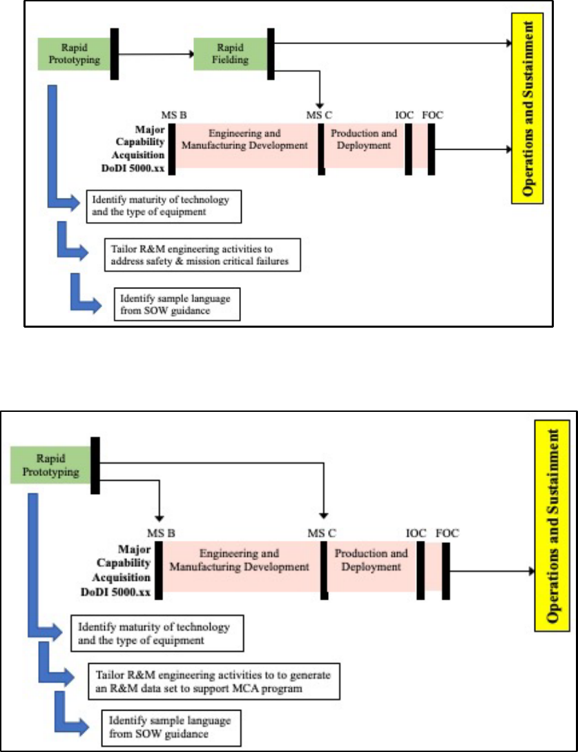
APPROVED FOR PUBLIC RELEASE
49
Figure A-3: Tailoring Flow Diagram for the RP Path: transition to RF
Figure A-4: Tailoring Flow Diagram for the RP Path: transition to MCA

APPROVED FOR PUBLIC RELEASE
50
Figure A-5: Tailoring Flow Diagram for the Software Acquisition Pathway

APPROVED FOR PUBLIC RELEASE
51
Appendix B Common Defect Enumeration (CDE)
1.0 Purpose and Background
The CDE provides a listing of software defects that are applicable for virtually all
software intensive systems.
Since the 1980s, there have been several “Software Bug Taxonomies”. These
taxonomies cover functional software defects, vulnerabilities, organizational defects,
documentation defects, testing, and other quality related defects.
The goal for this CDE is include defects that:
• Can be tested.
• Aren’t detected by automated code analysis tools.
• Represent the span of things that can and have gone wrong with software
systems
• Can be identified in the specifications and design as opposed to code reviews.
• Are cheaper to fix earlier rather than later.
Figure 1-1 illustrates the goals of the CDE within a continuous development
environment.
Figure 1-1 Goal of the CDE within DevOps

APPROVED FOR PUBLIC RELEASE
52
The focus for this enumeration is entirely on functional software defects that can
cause for a mission failure. All the defects enumerated can be tested. For example,
one common functional defect is when the software allows for a transition between two
states that is prohibited. The specification can be written to explicitly prohibit the
transition which invokes a test procedure. The software is then tested to ensure that it
rejects any prohibited transition. Without this specification the software test engineers
would be testing only the allowed transitions.
In contrast, organization defects typically lead to more defects but are not
necessarily directly traceable to a specific failure. For example, it has been proven that
when software engineers have industry experience with the application under
development that there are fewer software failures than otherwise
33
. This information is
useful for predicting the quantity of defects but not for identifying a specific defect that
will cause a specific mission event. In other words, one cannot develop a test case for
or design for the fact that the software engineers are not experienced with the system
under development.
Several software bug taxonomies focus on defects that can only be visible by
detailed code inspections. The goal of this CDE is to identify those that are visible long
before the code is written. Today’s weapon systems are far too large to wait until the
code is written to conduct a software failure mode effect analysis (SFMEA). The
defects introduced in the specifications typically have a wider effect and are less
detectable in testing than defects that are due to poor coding practices.
Since the 1980s, there have been various attempts to define software defects.
These were called “Taxonomies” because software defects were commonly referred to
as “bugs.” Table 1 shows the type of software defects that the authors enumerated.
When conducting a SFMEA the defects due to organization, documentation, and testing
are not analyzed as these cannot directly lead to a specific software failure. Defects
due to e-commerce and cyber security can be analyzed when conducting a SFMEA, but
this CDE does not address e-commerce and cyber security.
Defects due to object-oriented programming are applicable for a SFMEA but this
enumeration is focused more on the defects that originate in the specifications and
design.
33
This is proven by both of these quantitative studies: Cold Hard Truth about Reliable Software Edition 6j, and
Rome Laboratories TR-92-52, “Software Reliability Measurement and Test Integration Techniques”.
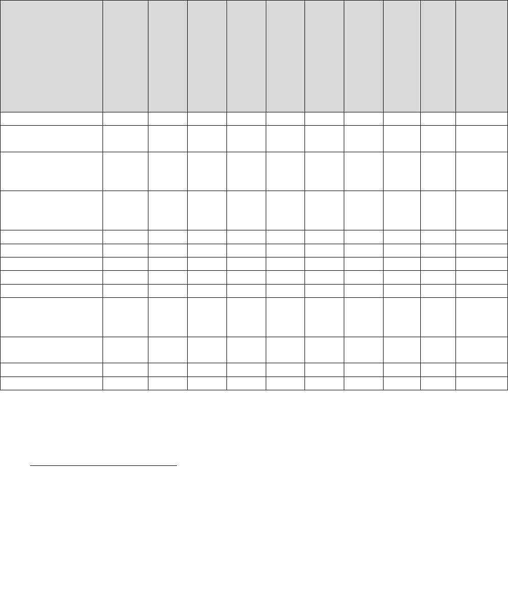
APPROVED FOR PUBLIC RELEASE
53
Taxonomy
Functional
specification level
Functional coding
level
Functional
interface
Functional top
level
Usability
Cyber security
Organizational
Documentation
Testing
Other “ ilities”
such as security,
interoperability
Boris Beizer
34
√
√
√
√
√
√
√
Kaner, Faulk and
Nguyen
35
√
√
√
√
√
Binder’s Object
Oriented
36
Taxonomy
√
√
√
Vijayaraghavan’s
E-commerce
Taxonomy
37
√
√
√
√
Whittaker
38
√
√
Hagar
39
√
√
√
√
√
Neufelder 2014
40
√
√
√
√
√
√
Neufelder 2021
41
√
√
JSSSEH
42
√
√
√
Mitre Common
Weakness
Enumeration
43
√
Rome Laboratory
TR-92-52
44
√
√
√
Neufelder 2019
45
√
Microsoft 2022
46
√
√
Table 1 Software Defect Taxonomies
34
Beizer, Boris Software Testing Techniques. Van Nostrand Reinhold, 1984.
35
Kaner, Cem, Jack Falk and Hung Quoc Nguyen (1999). Testing Computer Software (Second Edition). John Wiley & Sons.
36
Binder, Robert V. (2000). Testing Object-Oriented Systems: Models, Patterns, and Tools. Addison-Wesley.
37
Vijayaraghavan, Giri and Cem Kaner. "Bugs in your shopping cart: A Taxonomy."
http://www.testingeducation.org/articles/BISC_Final.pdf
38
Whittaker, James A. How to Break Software: A Practical Guide to Testing. Addison Wesley, 2003.
39
Hagar, Jon. Error/Fault Taxonomy Mind Map, 2021.
40
Neufelder, Ann Marie. Effective Application of Software Failure Modes Effects Analysis, 2014.
41
Neufelder, Ann Marie. CDE November 2021.
42
Joint Systems Software Safety Engineering Handbook, 2010.
43
https://cwe.mitre.org/
44
Rome Laboratories TR-92-52, “Software Reliability Measurement and Test Integration Techniques”.
45
Neufelder, Ann Marie. “Cold Hard Truth About Reliable Software, Edition 6j, 2019”
46
Failure mode analysis for Azure applications https://docs.microsoft.com/en-
us/azure/architecture/resiliency/failure-mode-analysis
APPROVED FOR PUBLIC RELEASE
54
2.0 Common Defect Enumeration Key
The common software defect enumeration is as follows:
<Architectural level> - <Failure Mode> - <Root cause #> - <Artifact> - <Artifact#>
2.1 Architectural Level
TL - Top level failure modes affect the entire software LRU. The root cause is not directly traceable to one capability or one
specification. These are also called mission level failures. This viewpoint provides for the widest coverage of the software but the
least level of detail.
CL - Capability Level failure modes and root causes affect one feature, use case, or capability. Example - launch, track,
engage, etc.
SL - SRS Level failure modes and root causes are related to exactly one software requirements specification that is faulty.
IL - Interface Level. These failure modes and root causes originate in the interface design specification. To analyze these
failure modes, the analysts will need to have an interface requirements specification or an interface design document.
DL- Detailed Level. These failure modes and root causes are visible only when looking at the source code. The detailed level
is usually too expensive to be applied across more than a small segment of the code. This level does not identify faults due to
poor specifications as it focuses purely on defects that are introduced in the coding activity. The CDE doesn’t discuss the detailed
level defects but those are available in the references shown in Table 1.
2.2 Failure Mode Categories
SM - State management - The software is unable to maintain state, executes incorrect transitions, dead states, etc.
EH - Error handling - The software is unable to identify, and handle known system faults.
T - Timing - The software executes the right thing too early or too late.
SE - Sequencing - The software executes the right thing in the wrong order.
DD - Data definition - The software has wrong or incompatible definitions of size, type, format, unit of measure, scale, etc.
PR - Processing - The software is unable to handle peak loading, extended duration, file I/O etc.
F - Functionality - The software does the wrong thing perfectly. The software does not meet the basic reason for the
software. For example, the Denver airport software was required to reduce baggage delivery time to the aircraft to support on
time delivery. The software was so poorly developed that it increased the time of baggage delivery to the aircraft.
A - Algorithm - The simplest algorithm is a division of two numbers. The most common algorithm fault is when the software
engineer fails to write code to handle a denominator that is near zero.
U - Usability - Usability faults caused by the software have led to mission faults.
ML - Machine learning - This includes faults due to data collection, labeling and modeling.
2.3 Root Cause #
This is a unique sequential identifier for multiple root causes related to the failure mode.
APPROVED FOR PUBLIC RELEASE
55
2.4 Artifact
Regardless of whether the level is top, capability, SRS, or interface, the root cause can originate in the following activities:
S - The root cause originates in the software specification (software requirements or interface requirements) due to omission or
commission.
D - The root cause originates in the software design due to omission or commission.
C - The root cause originates in the code. The specification and design are clearly correct.
2.5 Artifact #
This is a unique identifier for multiple root causes originating from the same artifact. This identifier is not always used.
Example: TL-SM-2-S-2 corresponds to a failure mode that applies to the entire software LRU or system related to state
management. This enumeration discusses the third root cause which originated in the specifications. It is the second type of
specification related root cause for this artifact.
2.6 Tailoring of CDEs
The CDEs should be filtered by applicability initially. If tailoring is required for time/budget constraints, the CDEs that are not
easily detectable in development or test should be considered first. In this CDE - failure modes of detectability level “5” (see
section 2.7) are higher risk because fault injection and/or special tools are required to detect in testing. In contrast, detectability
level “1” failure modes are obvious by functioning the system. Tailoring can also be established based on the effort required by
the software FMEA analysts to identify the failure mode. Some failure modes are easily identifiable in the documentation while
other failure modes may require involvement of subject matter experts / investigation teams (see skill / effort level section 2.7).
2.7 Detectability Level
1 - Failure mode will be immediately visible by simply turning on the system and performing any function.
2 - Failure mode will be detected via testing of a written requirement.
3 - Failure mode requires a specific code review to identify.
4 - Failure mode won't be identified by testing the software requirements.
5 - Failure mode requires fault injection and/or specific tools to identify.
2.8 Skill / effort required by SFMEA analyst
Low - The software FMEA analyst needs only a top level diagram / specifications to identify if this failure mode exists.
Medium - Someone must review the code to confirm or deny that this failure mode exists.
High - Usually requires an investigation by a subject matter expert.
2.9 CDE Tables
The CDE table has the following outline:
• Failure Mode ID: <Architecture level><Failure Mode><Root cause #>

APPROVED FOR PUBLIC RELEASE
56
• Failure Mode Description
• Discussion / Example of Failure Mode
• Tailoring Recommendation
• CDE: <Architecture level><Failure Mode><Root cause #><Artifact><Artifact#>. Note that this is not applicable for the
specification or interface levels as these are specification level by default.
• Description: The description is specific to the artifact level. The same root cause can originate in the requirements, design,
or code.
• Detectability Level
• Skill / Effort required by SFMEA analysts
• Applicability: Some CDEs are not always applicable while others are always applicable.
• Reference
3.0 Common Defect Enumeration Tables / Worksheets
For the latest CDE tables refer to the DAU R&M CoP website (https://www.dau.edu/cop/rm-engineering/Pages/Default.aspx).
The CDE spreadsheet has worksheets for each of the four (4) analysis levels (Top Level, Capability Level, Specification Level,
and Interface Level) as follows:

APPROVED FOR PUBLIC RELEASE
57
Top Level Failure Modes
Failure
Mode ID
Failure Mode
Description
Discussion/
Example of Failure
Mode
Tailoring
Recommendation
Common
Defect
Enumeration
Description
Detectability Level
Skill /
Effort required by
SFMEA analysts
Applicability
Reference
TL-SM-1
Prohibited state
transitions are
executed
Prohibited
transitions are
what lead to
irrecoverable
events such as
inadvertent
launches
This is applicable
for virtually all
software intensive
systems
TL-SM-1-S-1
The
specifications
fail to identify
allowed or
disallowed state
transitions.
4 - Since there is no specification this won't be
identified in testing
Low - prohibited
transitions are
easy to see on a
state diagram
All mission
critical systems
Neufelder
2021
Section 3.1
TL-SM-1-S-2
The
specifications
identify allowed
state transitions
but fail to
require that not
allowed
transitions are
explicitly
prohibited.
4 - Since there is no specification this won't be
identified in testing
Low - prohibited
transitions are
easy to see on a
state diagram
Neufelder
2021
Section 3.1,
BEIZER
7.2.2
TL-SM-1-C-1
The
specification for
prohibited
transitions is
clear but the
software
doesn't meet it.
3- Failure mode requires a specific code review
to identify
Medium - the
FMEA analyst
needs to read the
test procedures to
ensure this was
tested
Neufelder
2021
Section 3.1
TL-SM-2
(cont. on
next page)
Valid transitions
are allowed under
invalid conditions
(This is a
conditional
prohibited state
transition)
A transition made
with the wrong
criteria reduces to
a prohibited
transition which is
what lead to
irrecoverable
events such as
inadvertent
launches
This is applicable
for virtually all
software intensive
systems
TL-SM-2-S-1
The
specifications
fail to identify all
valid conditions
for all state
transitions.
4 - Since there is no specification this won't be
identified in testing
Low -
conditionally
prohibited
transitions are
easy to see on a
state diagram
All mission
critical systems
Neufelder
2021
Section 3.1
TL-SM-2-S-2
The
specifications
identify
conditions for
state transitions
but fail to
require that any
other conditions
are explicitly
prohibited.
4 - Since there is no specification this won't be
identified in testing
Low -
conditionally
prohibited
transitions are
easy to see on a
state diagram
Neufelder
2021
Section 3.1

APPROVED FOR PUBLIC RELEASE
58
Top Level Failure Modes
Failure
Mode ID
Failure Mode
Description
Discussion/
Example of Failure
Mode
Tailoring
Recommendation
Common
Defect
Enumeration
Description
Detectability Level
Skill /
Effort required by
SFMEA analysts
Applicability
Reference
TL-SM-2
(cont.)
TL-SM-2-C-1
The
specifications
clearly identify
the prohibited
transitions, but
the code allows
the prohibited
transition
3- Failure mode requires a specific code review
to identify
Medium - the
FMEA analyst
needs to read the
test procedures to
ensure this was
tested
BEIZER
7.2.2
Unspecified
transitions
TL-SM-3
States are stuck
(dead state. This
is most common
when an error
state is entered
but isn't reset
when the error is
corrected.)
Systems often get
stuck when they
enter an error
state, the error is
fixed and then the
user has to reboot
to clear the fault.
This is applicable
for virtually all
software intensive
systems
TL-SM-3-S-1
The
specifications
are missing an
exit criteria for a
state
(particularly
applicable to an
exit from an
error state).
4 - Since there is no specification this won't be
identified in testing
Low - the states
are easy to see
on a state
diagram
All mission
critical systems
Neufelder
2021
Section 3.1
TL-SM-3-C-1
The
specifications
indicate an
explicit exit from
every state but
the code
causes a dead
state in conflict
with the
specifications
2 - Failure mode will be detected via testing of a
written requirement
Medium - the
FMEA analyst
needs to read the
test procedures to
ensure this was
tested
Neufelder
2021
Section 3.1,
BEIZER
7.2.2
TL-SM-4
(continued
next page)
The software is
unstable after an
unexpected loss
of power while in
a particular state
Forgetting to
design for an
unexpected power
loss is a common
oversight. From a
software
perspective the
failure happens
when the power is
restored. The
software can be in
the wrong state or
unpredictable
state.
This is applicable
for virtually all
software intensive
systems
TL-SM-4-S-1
The
specifications
fail to identify
what the
software shall
do after an
unexpected
loss of power
for each and
every state.
4 - Since there is no specification this won't be
identified in testing
Low - the states
are easy to see
on a state
diagram
All mission
critical systems
Neufelder
2021
Section 3.1

APPROVED FOR PUBLIC RELEASE
59
Top Level Failure Modes
Failure
Mode ID
Failure Mode
Description
Discussion/
Example of Failure
Mode
Tailoring
Recommendation
Common
Defect
Enumeration
Description
Detectability Level
Skill /
Effort required by
SFMEA analysts
Applicability
Reference
TL-SM-4
(cont.)
TL-SM-4-S-2
The
specifications
identify what
the software
shall do after an
unexpected
power loss but
it isn't tailored to
each of the
states (i.e. the
appropriate
recovery may
be different
depending on
the state when
the power
outage occurs)
5 - The fact that a requirement is itself faulty is
never identified in testing
Low - the states
are easy to see
on a state
diagram
TL-SM-4-C-1
The
specifications
clearly identify
the behavior
required after
an unexpected
loss of power
for every state
but the code
doesn't
implement the
requirements
2 - Failure mode will be detected via testing of a
written requirement
Medium - the
FMEA analyst
needs to read the
test procedures to
ensure this was
tested
TL-SM-5
(continued
on next
page)
The software is
unstable after an
unexpected user
abort while in a
particular state
Software
engineers often fail
to consider all of
the possible states
that a user can
execute an abort.
Sometimes it may
be required to
disable the abort.
(Ex: when
upgrading an
operating system
the user is not
allowed to reboot).
Depending on the
state in which the
user aborts, there
This is applicable
for any system with
a user interface
TL-SM-5-S-1
The
specifications
fail to identify
what the
software shall
do after an
unexpected
user abort for
each and every
state.
4 - Since there is no specification this won't be
identified in testing
Low - the states
are easy to see
on a state
diagram
All mission
critical systems
Neufelder
2021
Section 3.1

APPROVED FOR PUBLIC RELEASE
60
Top Level Failure Modes
Failure
Mode ID
Failure Mode
Description
Discussion/
Example of Failure
Mode
Tailoring
Recommendation
Common
Defect
Enumeration
Description
Detectability Level
Skill /
Effort required by
SFMEA analysts
Applicability
Reference
TL-SM-5
(cont.)
could be
dramatically
different required
behavior.
TL-SM-5-S-2
The
specifications
identify what
the software
shall do after an
unexpected
user abort but it
isn't tailored to
each of the
states (i.e. the
appropriate
recovery may
be different
depending on
the state when
the abort
occurs)
5 - The fact that a requirement is itself faulty is
never identified in testing
Low - the states
are easy to see
on a state
diagram
Neufelder
2021
Section 3.1
TL-SM-5-C-1
The
specifications
clearly identify
the behavior
required after
an unexpected
user for every
state but the
code doesn't
implement the
requirements
2-Failure mode will be detected via testing of a
written requirement
Medium - the
FMEA analyst
needs to read the
test procedures to
ensure this was
tested
Neufelder
2021
Section 3.1,
Kaner/Faulk/
Nguyen
page 369
Aborting
errors
TL-SM-6
(continued
on next
page)
The software is
missing a fault or
safe state
if a weapon is
failed it needs to
be in a reduced
capability state.
This is applicable
for virtually all
software intensive
systems
TL-SM-6-S-1
The
specification
does not
explicitly
identify a fault
or safe state
4 - Since there is no specification this won't be
identified in testing
Low - it's easy to
determine if there
is no faulted or
safe state just
from looking at a
diagram
All mission
critical systems.
Note that this is
typically required
for safety critical
systems.
JSSSEH
Appendix
E.3.1

APPROVED FOR PUBLIC RELEASE
61
Top Level Failure Modes
Failure
Mode ID
Failure Mode
Description
Discussion/
Example of Failure
Mode
Tailoring
Recommendation
Common
Defect
Enumeration
Description
Detectability Level
Skill /
Effort required by
SFMEA analysts
Applicability
Reference
TL-SM-6
(cont.)
TL-SM-6-C-1
The
specification
identifies a fault
or safe state but
it's not
implemented in
the code
2 - Failure mode will be detected via testing of a
written requirement
Medium - The
FMEA analyst
needs to read the
test procedures to
ensure this was
tested
TL-SM-7
The software is
missing a
transition to a fault
or safe state
In addition to
having a fault/safe
state there also
needs to be a
transition to the
fault or safe state
This is applicable
for virtually all
software intensive
systems
TL-SM-7-S-1
The
specification
fails to identify
at least one
transition to a
fault or safe
state
4 - Since there is no specification this won't be
identified in testing
Low - it's easy to
determine if there
is no transition to
a faulted or safe
state just from
looking at a
diagram
All mission
critical systems.
Note that this is
typically required
for safety critical
systems.
JSSSEH
Appendix
E.3.2
TL-SM-7-C-1
The
specification
identifies at
least one
transition to a
fault or safe
state but it's not
implemented in
the code
2-Failure mode will be detected via testing of a
written requirement
Medium - the
FMEA analyst
needs to read the
test procedures to
ensure this was
tested
TL-SM-8
(continued
on next
page)
The behavior of
the fault or safe
state is
inappropriate for
the system
mission
Once the software
enters the safe or
fault state it must
execute the
correct behavior.
In some cases that
means doing
nothing. In other
cases it might
mean attempting
to heal the fault.
This is applicable
for virtually all
software intensive
systems
TL-SM-8-S-1
The
specification
identifies an
inappropriate
behavior once
the software
enters a safe or
fault state (i.e.
rebooting
instead of
ignoring
commands.)
4 - Since there is no specification this won't be
identified in testing
Medium - The
"correct" behavior
usually requires
someone with
knowledge of the
system
All mission
critical systems
Neufelder
2021
Section 3.1

APPROVED FOR PUBLIC RELEASE
62
Top Level Failure Modes
Failure
Mode ID
Failure Mode
Description
Discussion/
Example of Failure
Mode
Tailoring
Recommendation
Common
Defect
Enumeration
Description
Detectability Level
Skill /
Effort required by
SFMEA analysts
Applicability
Reference
TL-SM-8
(cont.)
TL-SM-8-C-1
The
specification
identifies an
appropriate
fault state
behavior but it's
not
implemented in
the code
2-Failure mode will be detected via testing of a
written requirement
Medium - The
FMEA analyst
needs to read the
test procedures to
ensure this was
tested
TL-SM-9
The software as a
whole is missing a
state
This is a general
version of TL-SM-
6. The software
might be missing
any state. This can
happen if there are
many states.
This is applicable
for virtually all
software intensive
systems
TL-SM-9-S-1
The top level
specifications
are missing a
required state.
4 - Since there is no specification this won't be
identified in testing
Medium -
Understanding
what is missing
usually requires
knowledge of the
system
All mission
critical systems
Neufelder
2021
Section 3.1
TL-SM-9-C-1
The
specifications
discuss all
states but the
software
doesn't
implement all
states.
2-Failure mode will be detected via testing of a
written requirement
Medium - the
FMEA analyst
needs to read the
test procedures to
ensure this was
tested
TL-SM-10
The software as a
whole is missing a
state transition
This is a general
version of TL-SM-
7. The software
might be missing
any state transition
This can happen if
there are many
states and
transitions.
This is applicable
for virtually all
software intensive
systems
TL-SM-10-S-1
The top level
specifications
are missing a
required state
transition.
4 - Since there is no specification this won't be
identified in testing
Medium -
Understanding
what is missing
usually requires
knowledge of the
system
All mission
critical systems
Neufelder
2021
Section 3.1
TL-SM-10-C-1
The
specifications
discuss all state
transitions but
the software
doesn't
implement all
states.
2 - Failure mode will be detected via testing of a
written requirement
Medium - The
FMEA analyst
needs to read the
test procedures to
ensure this was
tested

APPROVED FOR PUBLIC RELEASE
63
Top Level Failure Modes
Failure
Mode ID
Failure Mode
Description
Discussion/
Example of Failure
Mode
Tailoring
Recommendation
Common
Defect
Enumeration
Description
Detectability Level
Skill /
Effort required by
SFMEA analysts
Applicability
Reference
TL-SM-11
(continued
on next
page)
The software
commits a
prohibited
transition to
different feature (a
different state
machine) within
the software
This is similar to
TL-SM-1 except
that the software
allows a prohibited
transition to a
different feature
within the
software.
This is applicable
for virtually all
software intensive
systems
TL-SM-11-S-1
The
specifications
fail to identify
that a particular
state machine
cannot execute
a prohibited
state transition
from another
state machine
4 - Since there is no specification this won't be
identified in testing
Low - Prohibited
transitions are
easy to see on a
state diagram
All mission
critical systems
TL-SM-11-S-2
The
specifications
identify allowed
state transitions
but fail to
require that not
allowed
transitions are
explicitly
prohibited
4 - Since there is no specification this won't be
identified in testing
Low - Prohibited
transitions are
easy to see on a
state diagram
TL-SM-11-C-1
The
specification for
prohibited
transitions is
clear but the
software
doesn't meet it.
3- Failure mode requires a specific code review
to identify
Medium - the
FMEA analyst
needs to read the
test procedures to
ensure this was
tested
TL-SM-12
(continued
on next
page)
The software
accommodates a
prohibited
transition from a
different software
feature (a different
state machine)
This is similar to
TL-SM-11 except
that the software
allows a prohibited
transition from a
different feature
within the
software.
This is applicable
for virtually all
software intensive
systems
TL-SM-12-S-1
The
specifications
fail to identify
that a particular
state machine
cannot accept a
prohibited state
transition from
another state
machine
4 - Since there is no specification this won't be
identified in testing
Low - prohibited
transitions are
easy to see on a
state diagram
All mission
critical systems
Neufelder
2021
Section 3.1

APPROVED FOR PUBLIC RELEASE
64
Top Level Failure Modes
Failure
Mode ID
Failure Mode
Description
Discussion/
Example of Failure
Mode
Tailoring
Recommendation
Common
Defect
Enumeration
Description
Detectability Level
Skill /
Effort required by
SFMEA analysts
Applicability
Reference
TL-SM-12
(cont.)
TL-SM-12-S-2
The
specifications
identify allowed
state transitions
but fail to
require that not
allowed
transitions are
explicitly
prohibited
4 - Since there is no specification this won't be
identified in testing
Low - prohibited
transitions are
easy to see on a
state diagram
Neufelder
2021
Section 3.1,
BEIZER
7.2.2
TL-SM-12-C-1
The
specification for
prohibited
transitions is
clear but the
software
doesn't meet it.
3 - Failure mode requires a specific code review
to identify
Medium - the
FMEA analyst
needs to read the
test procedures to
ensure this was
tested
Neufelder
2021
Section 3.1
TL-EH-1
Hardware faults
aren't detected
Whether the
software
requirements say
so or not, it's the
job of the software
to detect any and
all hardware faults.
Hardware faults
includes sensors,
weapon hardware,
etc.
This is applicable
for virtually all
software intensive
systems
TL-EH-1-S-1
There is no
specification
that requires
that the
software detect
all known
hardware faults
5 - There is no specification and this requires
fault injection testing to identify
Low - the
hardware faults
are well
established.
Either the
specifications
discuss detecting
these or they
don't
All weapons,
combat and
mission systems
Neufelder
2021
Section 3.1
TL-EH-1-C-1
There is an
overarching
specification but
one or more
contractor/LRU
ignored the
specification
2-Failure mode will be detected via testing of a
written requirement
Medium - the
FMEA analyst
needs to read the
test procedures to
ensure this was
tested
Neufelder
2021
Section 3.1,
BEIZER
Bugs in
perspective
section 3.3,
Kaner/Faulk/
Nguyen
page 369
Ignore
hardware
faults

APPROVED FOR PUBLIC RELEASE
65
Top Level Failure Modes
Failure
Mode ID
Failure Mode
Description
Discussion/
Example of Failure
Mode
Tailoring
Recommendation
Common
Defect
Enumeration
Description
Detectability Level
Skill /
Effort required by
SFMEA analysts
Applicability
Reference
TL-EH-2
Hardware faults
are detected but
aren't
appropriately
handled
Detecting
hardware faults is
only half of what's
needed. The
software must
execute the
correct behavior
based on the type
of hardware fault.
One common fault
is for the software
to "reboot" when
the hardware fails.
This is rarely the
right behavior.
This is applicable
for virtually all
software intensive
systems
TL-EH-2-S-1
There is no
specification for
how the
software will
handle a
hardware fault
once detected
5 - There is no specification and this requires
fault injection testing to identify
Medium -
Understanding
what is
"appropriate"
requires
knowledge of the
system
All weapons,
combat and
mission systems
Neufelder
2021
Section 3.1
TL-EH-2-C-1
There is an
overarching
specification but
one or more
contractor/LRU
ignored the
specification
2-Failure mode will be detected via testing of a
written requirement
Medium - the
FMEA analyst
needs to read the
test procedures to
ensure this was
tested
Neufelder
2021
Section 3.1.
Kaner/Faulk/
Nguyen
page 369
Ignore
hardware
faults.
Recovery
from
hardware
problems.
TL-EH-3
(continued
next page)
Communication
faults aren't
detected
The software
needs to detect a
loss of
communication
regardless of
whether the
software
requirements say
so.
This is applicable
for virtually all
software intensive
systems
TL-EH-3-S-1
There is no
specification
that requires
that the
software detect
all comm faults
5 - There is no specification and this requires
fault injection testing to identify
Low - either the
specifications
discuss detection
of communication
faults or they don't
Any network
system
Neufelder
2021
Section 3.1

APPROVED FOR PUBLIC RELEASE
66
Top Level Failure Modes
Failure
Mode ID
Failure Mode
Description
Discussion/
Example of Failure
Mode
Tailoring
Recommendation
Common
Defect
Enumeration
Description
Detectability Level
Skill /
Effort required by
SFMEA analysts
Applicability
Reference
TL-EH-3
(cont.)
TL-EH-3-S-2
There is no
specification for
the software to
detect a
connection to a
Virtual Machine
that fails or a
VM instance
that is
unhealthy
5 - There is no specification and this requires
fault injection testing to identify
Low - Either the
specifications
discuss detecting
these or they
don't
Virtual machines
Microsoft
2022
TL-EH-3-C-1
There is an
overarching
specification but
one or more
contractor/LRU
ignored the
specification
2-Failure mode will be detected via testing of a
written requirement
Medium - the
FMEA analyst
needs to read the
test procedures to
ensure this was
tested
Any network
system
Neufelder
2021
Section 3.1
TL-EH-4
(continued
on next
page)
Communication
faults are
detected but
aren't
appropriately
handled
Detecting
communication
faults is only half
of what's needed.
The software must
execute the
correct behavior
once the fault is
detected. One
common fault is for
the software to
"reboot" when
there is a comm
failure. This is
rarely the right
behavior.
This is applicable
for virtually all
software intensive
systems
TL-EH-4-S-1
There is no
specification
that specifically
states what the
software should
do when there
is a comm fault.
5 - There is no specification and this requires
fault injection testing to identify
Medium -
Understanding
what is
"appropriate"
requires
knowledge of the
system
Any network
system
Neufelder
2021
Section 3.1
TL-EH-4-S-2
There is no
specification for
the software to
properly
recover from a
connection to a
Virtual Machine
that fails or a
VM instance
that is
unhealthy
5 - There is no specification and this requires
fault injection testing to identify
Low - Either the
specifications
discuss detecting
these or they
don't
Virtual machines
Microsoft
2022

APPROVED FOR PUBLIC RELEASE
67
Top Level Failure Modes
Failure
Mode ID
Failure Mode
Description
Discussion/
Example of Failure
Mode
Tailoring
Recommendation
Common
Defect
Enumeration
Description
Detectability Level
Skill /
Effort required by
SFMEA analysts
Applicability
Reference
TL-EH-4
(cont.)
TL-EH-4-C-1
There is an
overarching
specification but
one or more
contractor/LRU
ignored the
specification
2-Failure mode will be detected via testing of a
written requirement
Medium - the
FMEA analyst
needs to read the
test procedures to
ensure this was
tested
Any network
system
Neufelder
2021
Section 3.1
TL-EH-5
Computational
faults aren't
detected
Computational
faults are when
software
computations don't
consider all
possible inputs or
outputs. One
example is the
"NaN" - not a
number fault when
the software
doesn't consider
data is that is not
numeric. These
need to be
detected whether
the specification
says so or not.
This is applicable
for virtually all
software intensive
systems. It is most
relevant for any
software that is
performing any
calculations.
TL-EH-5-S-1
There is no
specification
that specifically
states that the
software shall
detect all
computational
faults.
4 - Since there is no specification this won't be
identified in testing
Medium -
Someone with
understanding of
where the
computational
faults lurk is
required to do this
analysis
All mission
critical systems
Neufelder
2021
Section 3.1
TL-EH-5-C-1
There is an
overarching
specification but
one or more
contractor/LRU
ignored the
specification
3- Failure mode requires a specific code review
to identify
Medium - the
FMEA analyst
needs to read the
test procedures to
ensure this was
tested
TL-EH-6
(continued
next page)
Computational
faults are
detected and
aren't
appropriately
handled
Detecting
computational
faults is only half
of what's needed.
The software must
execute the
correct behavior
once the fault is
detected. One
common fault is for
the software to
"reboot" when
there is a
This is applicable
for virtually all
software intensive
systems. It is most
relevant for any
software that is
performing any
calculations.
TL-EH-6-S-1
There is no
specification
that specifically
states what the
software should
do when there
is a
computational
fault.
4 - Since there is no specification this won't be
identified in testing
Medium -
Someone with
understanding of
where the
computational
faults lurk is
required to do this
analysis
All mission
critical systems
Neufelder
2021
Section 3.1

APPROVED FOR PUBLIC RELEASE
68
Top Level Failure Modes
Failure
Mode ID
Failure Mode
Description
Discussion/
Example of Failure
Mode
Tailoring
Recommendation
Common
Defect
Enumeration
Description
Detectability Level
Skill /
Effort required by
SFMEA analysts
Applicability
Reference
TL-EH-6
(cont.)
computational
failure. This is
rarely the right
behavior.
TL-EH-6-C-1
There is an
overarching
specification but
one or more
contractor/LRU
ignored the
specification
3- Failure mode requires a specific code review
to identify
Medium -
Someone with
understanding of
where the
computational
faults lurk is
required to do this
analysis
TL-EH-7
Power faults (i.e.
wrong voltages)
aren't detected
Power faults are
when the software
allows an out of
range voltage or
current or doesn't
allow an in range
voltage or current.
This is applicable
for any system that
has specific power
up requirements.
TL-EH-7-S-1
There is no
specification
that specifically
states the
voltages that
are out of range
and the fact that
the software
must detect this
event.
5 - There is no specification and this requires
fault injection testing to identify
Low - The power
requirements in a
specification are
easy to identify
All weapons,
combat and
mission systems
Neufelder
2021
Section 3.1
TL-EH-7-C-1
There is an
overarching
specification but
one or more
contractor/LRU
ignored the
specification
2-Failure mode will be detected via testing of a
written requirement
Medium - The
FMEA analyst
needs to read the
test procedures to
ensure this was
tested
TL-EH-8
(continued
next page)
Power faults (i.e.
wrong voltages)
are detected but
aren't
appropriately
handled
Sometimes the
software engineers
may design a one
size fits all for
voltage faults such
as endless loops
that wait for the
voltages to
converge or
prematurely
declaring a
This is applicable
for any system that
has specific power
up requirements.
TL-EH-8-S-1
There is a
specification for
detecting power
faults but the
specified
recovery is
inappropriate.
5 - There is no specification and this requires
fault injection testing to identify
Medium -
Understanding
what is
"appropriate"
requires
knowledge of the
system
All weapons,
combat and
mission systems
Neufelder
2021
Section 3.1

APPROVED FOR PUBLIC RELEASE
69
Top Level Failure Modes
Failure
Mode ID
Failure Mode
Description
Discussion/
Example of Failure
Mode
Tailoring
Recommendation
Common
Defect
Enumeration
Description
Detectability Level
Skill /
Effort required by
SFMEA analysts
Applicability
Reference
TL-EH-8
(cont.)
weapon NMC.
TL-EH-8-C-1
There is an
overarching
specification but
one or more
contractor/LRU
ignored the
specification
2 - Failure mode will be detected via testing of a
written requirement
Medium - The
FMEA analyst
needs to read the
test procedures to
ensure this was
tested
TL-EH-9
Battery depletion
isn't detected prior
to depletion
Detection /
monitoring of
battery depletion
may be critical
This is applicable
for any battery
powered system
TL-EH-9-S-1
There is no
specification for
detecting low
battery.
5 - There is no specification and this requires
fault injection testing to identify
Low - The battery
depletion
detection
requirements in a
specification are
easy to identify
Any battery
operated system
Neufelder
2021
Section 3.1
TL-EH-9-C-1
There is an
overarching
specification but
one or more
contractor/LRU
ignored the
specification
2-Failure mode will be detected via testing of a
written requirement
Medium - the
FMEA analyst
needs to read the
test procedures to
ensure this was
tested
TL-EH-10
(continued
next page)
Battery depletion
is detected but
aren't
appropriately
handled
Detection/monitori
ng of battery
depletion may be
critical
This is applicable
for any battery
powered system
TL-EH-10-S-1
There is a
specification for
how low battery
is handled but
the specified
recovery is
inappropriate.
5 - There is no specification and this requires
fault injection testing to identify
Medium -
Understanding
what is
"appropriate"
requires
knowledge of the
system
Any battery
operated system
Neufelder
2021
Section 3.1

APPROVED FOR PUBLIC RELEASE
70
Top Level Failure Modes
Failure
Mode ID
Failure Mode
Description
Discussion/
Example of Failure
Mode
Tailoring
Recommendation
Common
Defect
Enumeration
Description
Detectability Level
Skill /
Effort required by
SFMEA analysts
Applicability
Reference
TL-EH-10
(cont.)
TL-EH-10-C-1
There is an
overarching
specification but
one or more
contractor/LRU
ignored the
specification
2 - Failure mode will be detected via testing of a
written requirement
Medium - the
FMEA analyst
needs to read the
test procedures to
ensure this was
tested
TL-EH-11
CRC faults aren't
detected
Detection of Cyclic
Redundancy
Check ensures
that there isn't
noise in
transmission.
This is applicable
for most real time
systems. Some
systems need a
CRC check and
don't have one.
TL-EH-11-S-1
There is no
specification for
CRC checking
5 - This requires a specialized tool and set up to
identify
This is highly
recommended
since CRC faults
are often serious
and the checks for
CRC faults are
relatively simple.
All mission
critical systems.
Note that this is
typically required
for safety critical
systems.
JSSSEH
Appendix
E.8.5
TL-EH-11-C-1
There is an
overarching
specification but
one or more
contractor/LRU
ignored the
specification
5 - This requires a specialized tool and set up to
identify
Medium - the
FMEA analyst
needs to read the
test procedures to
ensure this was
tested
TL-EH-12
(continued
next page)
CRC faults are
detected but not
appropriately
handled
Even if a CRC
fault is detected it
many be handled
inappropriately
This is applicable
for most real time
systems. Some
systems need a
CRC check and
don't have one.
TL-EH-12-S-1
There is a
specification for
CRC handling
but it is
inappropriate
5 - This requires a specialized tool and set up to
identify
Medium -
Understanding
what is
"appropriate"
requires
knowledge of the
system
All mission
critical systems.
Note that this is
typically required
for safety critical
systems.
JSSSEH
Appendix
E.8.5

APPROVED FOR PUBLIC RELEASE
71
Top Level Failure Modes
Failure
Mode ID
Failure Mode
Description
Discussion/
Example of Failure
Mode
Tailoring
Recommendation
Common
Defect
Enumeration
Description
Detectability Level
Skill /
Effort required by
SFMEA analysts
Applicability
Reference
TL-EH-12
(cont.)
TL-EH-12-C-1
There is an
overarching
specification but
one or more
contractor/LRU
ignored the
specification
5 - This requires a specialized tool and set up to
identify
Medium - The
FMEA analyst
needs to read the
test procedures to
ensure this was
tested
TL-EH-13
File I/O faults
aren't detected
File I/O faults
include files not
found, files can't
open, files read
error, file write
error, files building
up on a computer
drive.
This is applicable
for any software
that interfaces with
any files such as a
database, ini files,
text files, etc. Data
logging for example
writes to a file.
TL-EH-13-D-1
There is no
design for file
I/O faults
4 - Since there is no specification this won't be
identified in testing
Medium - The
analyst needs to
understand how
to identify
functions that are
reading/writing to
files
Any software
LRU that has
any file input
output (i.e. data
logging, text
files, etc.)
Neufelder
2021
Section 3.1
TL-EH-13-C-1
There is a
design
requirement for
file I/O checks
but one or more
contractor/LRU
ignored the
specification
2-Failure mode will be detected via testing of a
written requirement
Medium - the
FMEA analyst
needs to read the
test procedures to
ensure this was
tested
TL-EH-14
(continued
next page)
File I/O faults are
detected but not
appropriately
handled
Detecting an I/O
fault is only half of
what's needed.
Appropriate
recovery is the
other half.
Rebooting or "one
size fits all" error
recovery are rarely
appropriate.
This is applicable
for any software
that interfaces with
any files such as a
database, ini files,
text files, etc. Data
logging for example
writes to a file.
TL-EH-14-D-1
The design for
handling file I/O
faults is
inappropriate
(one size fits all
or unnecessary
reboot)
4 - Since there is no specification this won't be
identified in testing
Medium -
Understanding
what is
"appropriate"
requires
knowledge of the
system
Virtually all
software
systems have
file I/O
Neufelder
2021
Section 3.1

APPROVED FOR PUBLIC RELEASE
72
Top Level Failure Modes
Failure
Mode ID
Failure Mode
Description
Discussion/
Example of Failure
Mode
Tailoring
Recommendation
Common
Defect
Enumeration
Description
Detectability Level
Skill /
Effort required by
SFMEA analysts
Applicability
Reference
TL-EH-14
(cont.)
TL-EH-14-C-1
There is an
appropriate
design
requirement for
handling file I/O
checks but one
or more
contractor/LRU
ignored the
specification
2 - Failure mode will be detected via testing of a
written requirement
Medium - The
FMEA analyst
needs to read the
test procedures to
ensure this was
tested
TL-EH-15
Multiple
simultaneous
faults aren't
detected
Software
engineers often fail
to consider that
more than one
fault can occur at
about the same
time.
Consequently the
first failure or last
failure may not be
recorded.
This is applicable
for virtually any
software system
TL-EH-15-S-1
There
specifications
for faults don't
consider that
there could be
more than one
at a time
5 - There is no specification and this requires
fault injection testing to identify
Low - either the
specifications
discuss detection
of multiple faults
All mission
critical systems
Neufelder
2021
Section 3.1
TL-EH-15-C-1
There is a
requirement for
detecting
multiple
concurrent
faults but one or
more
contractor/LRU
ignored the
specification
2-Failure mode will be detected via testing of a
written requirement
Medium - the
FMEA analyst
needs to read the
test procedures to
ensure this was
tested
TL-EH-16
(continued
next page)
Multiple
simultaneous
faults are
detected but not
appropriately
handled
Detecting multiple
faults is half of
what's required.
Properly handling
multiple concurrent
faults is the other
half. Examples of
improper handling
include reporting
of the less
important fault
This is applicable
for virtually any
software system
TL-EH-16-S-1
There are
specifications
for concurrent
fault detection
but the handling
is inappropriate.
5 - There is no specification and this requires
fault injection testing to identify
Medium -
Understanding
what is
"appropriate"
requires
knowledge of the
system
All mission
critical systems
Neufelder
2021
Section 3.1

APPROVED FOR PUBLIC RELEASE
73
Top Level Failure Modes
Failure
Mode ID
Failure Mode
Description
Discussion/
Example of Failure
Mode
Tailoring
Recommendation
Common
Defect
Enumeration
Description
Detectability Level
Skill /
Effort required by
SFMEA analysts
Applicability
Reference
TL-EH-16
(cont.)
before the more
important fault,
addressing one
fault at a time even
though the
concurrent faults
might be related.
TL-EH-16-C-1
There is an
appropriate
requirement for
handling
multiple
concurrent
faults but one or
more
contractor/LRU
ignored the
specification
2 - Failure mode will be detected via testing of a
written requirement
Medium - The
FMEA analyst
needs to read the
test procedures to
ensure this was
tested
TL-EH-17
Multiple
sequential faults
aren't detected
Software
engineers often fail
to consider that
more than one
fault can occur in a
sequence.
Consequently, the
first failure or last
failure may not be
recorded.
This is applicable
for virtually any
software system
TL-EH-17-S-1
There
specifications
for faults don't
consider that
there could be
more than one
at a time
5 - There is no specification and this requires
fault injection testing to identify
Low - either the
specifications
discuss detection
of multiple faults
All mission
critical systems
Neufelder
2021
Section 3.1
TL-EH-17-C-1
There is a
requirement for
detecting
multiple
concurrent
faults but one or
more
contractor/LRU
ignored the
specification
2 - Failure mode will be detected via testing of a
written requirement
Medium - The
FMEA analyst
needs to read the
test procedures to
ensure this was
tested
TL-EH-18
(continued
on next
page)
Multiple
sequential faults
are detected but
not appropriately
handled
Detecting multiple
faults is half of
what's required.
Properly handling
multiple sequential
faults is the other
half. Examples of
improper handling
include reporting
of the less
important fault
This is applicable
for virtually any
software system
TL-EH-18-S-1
There are
specifications
for sequential
fault detection
but the handling
is inappropriate.
5 - There is no specification and this requires
fault injection testing to identify
Medium -
Understanding
what is
"appropriate"
requires
knowledge of the
system
All mission
critical systems
Neufelder
2021
Section 3.1

APPROVED FOR PUBLIC RELEASE
74
Top Level Failure Modes
Failure
Mode ID
Failure Mode
Description
Discussion/
Example of Failure
Mode
Tailoring
Recommendation
Common
Defect
Enumeration
Description
Detectability Level
Skill /
Effort required by
SFMEA analysts
Applicability
Reference
TL-EH-18
(cont.)
before the more
important fault,
hiding the faults
until the fault first
detected is
recovered from,
etc.
TL-EH-18-C-1
There is an
appropriate
requirement for
handling
multiple
concurrent fault
handling but
one or more
contractor/LRU
ignored the
specification
2-Failure mode will be detected via testing of a
written requirement
Medium - the
FMEA analyst
needs to read the
test procedures to
ensure this was
tested
TL-EH-19
(continued
next page)
BIT software
returns a false
negative
A false negative
BIT result can
happen if 1) BIT
results are
reversed 2) if early
BIT failures are
overwritten by later
BIT passes or 3)
BIT results are
improperly ANDed
instead of ORed or
4) the software
proceeds to the
next BIT test when
it should stop at
the first BIT failure.
Applicable for any
software that has
Power On Self Test
or Bit InTest or
Continuous BIT or
Periodic BIT
TL-EH-19-S-1
There aren't
detailed
specifications
for how BIT
results are
processed to
avoid all 4
potential BIT
reversals to
ensure early
BIT failures
aren't
overwritten by
later BIT
passes.
5 - There is no specification and this requires
fault injection testing to identify
Low - Any
software with BIT
is subject to this
failure mode.
Any system with
Built In Test
Neufelder
2021
Section 3.1
TL-EH-19-C-1
There are
detailed
specifications
for BIT results
to ensure that
all 4 potential
BIT reversals
but the code
isn't written to
specification.
3 - Failure mode requires a specific code review
to identify
Medium - the
FMEA analyst
needs to read the
test procedures to
ensure this was
tested

APPROVED FOR PUBLIC RELEASE
75
Top Level Failure Modes
Failure
Mode ID
Failure Mode
Description
Discussion/
Example of Failure
Mode
Tailoring
Recommendation
Common
Defect
Enumeration
Description
Detectability Level
Skill /
Effort required by
SFMEA analysts
Applicability
Reference
TL-EH-20
(continued
on next
page)
TL-EH-20
(cont.)
BIT software
returns a false
positive
A false positive
BIT result can
happen if 1) There
was previously a
failed BIT result
that wasn't cleared
from memory or 2)
BIT results are
reversed.
Applicable for any
software that has
Power On Self Test
or Bit InTest or
Continuous BIT or
Periodic BIT
TL-EH-20-S-1
There aren't
detailed
specifications
for how BIT
results are
processed to
avoid all 2
potential BIT
reversals
leading to false
BIT positive.
5 - There is no specification and this requires
fault injection testing to identify
Low - Any
software with BIT
is subject to this
failure mode.
Any system with
Built In Test
Neufelder
2021
Section 3.1
TL-EH-20-C-1
There are
detailed
specifications
for BIT results
to ensure that
all 2 potential
BIT reversals
but the code
isn't written to
specification.
3 - Failure mode requires a specific code review
to identify
Medium - the
FMEA analyst
needs to read the
test procedures to
ensure this was
tested
TL-EH-21
(continued
next page)
Software is
unable to handle
known user input
errors
Humans will with
100% input
incorrect data.
Software
engineers often
assume otherwise.
This is applicable
for any software
with a user interface
TL-EH-21-S-1
There are
specifications
for the software
to range
change every
mission critical
user input
4 - Since there is no specification this won't be
identified in testing
Low - the FMEA
analyst can
identify all user
inputs as per the
user interface
specification or
user manual.
Any system with
a user interface.
This could be
required for
safety critical
systems.
JSSSEH
Appendix E
TL-EH-21-C-1
There is an
appropriate
requirement for
handling invalid
user inputs but
one or more
contractors/LR
U ignored the
specification
2 - Failure mode will be detected via testing of a
written requirement
Medium - The
FMEA analyst
needs to read the
test procedures to
ensure this was
tested
BEIZER
Bugs in
Perspective
3.5, 5.0

APPROVED FOR PUBLIC RELEASE
76
Top Level Failure Modes
Failure
Mode ID
Failure Mode
Description
Discussion/
Example of Failure
Mode
Tailoring
Recommendation
Common
Defect
Enumeration
Description
Detectability Level
Skill /
Effort required by
SFMEA analysts
Applicability
Reference
TL-EH-22
(continued
on next
page)
TL-EH-22
(cont.)
The software
does not clear out
faults that have
been resolved
When faults are
resolved they need
to be marked so
that the user can
focus only on the
unresolved faults.
Software
engineers often
forget to clear
resolved faults
from the user
interface.
This is applicable
for all software
systems
TL-EH-22-S-1
There are
specifications
for the software
to clear out
faults that are
resolved.
5 - There is no specification and this requires
fault injection testing to identify
Low - Either there
are specifications
to clear out the
detected faults or
there are not
All mission
critical systems
Neufelder
2021
Section 3.1
TL-EH-22-C-1
There are
requirements
for clearing
faults but one or
more
contractors/LR
U ignored the
specification
2 - Failure mode will be detected via testing of a
written requirement
Medium - The
FMEA analyst
needs to read the
test procedures to
ensure this was
tested
Neufelder
2021
Section 3.1,
Kaner/Faulk/
Nguyen
page 369
Where does
program go
back to?
TL-EH-23
The software is
overly sensitive to
faults
This happens
when the criteria
for the fault doesn't
have any buffer for
determining the
fault. A
commercial
example - if a
person pays their
mortgage and is
one penny short
This is applicable
for all software
systems
TL-EH-23-S-1
There are
specific
requirements to
provide for
confidence
ranges or
waiting periods
to ensure that
the fault is
actually a fault.
4 - Since there is no specification this won't be
identified in testing
Medium -
Identifying over-
sensitivity typically
requires
knowledge of the
system
All mission
critical systems
Neufelder
2021
Section 3.1

APPROVED FOR PUBLIC RELEASE
77
Top Level Failure Modes
Failure
Mode ID
Failure Mode
Description
Discussion/
Example of Failure
Mode
Tailoring
Recommendation
Common
Defect
Enumeration
Description
Detectability Level
Skill /
Effort required by
SFMEA analysts
Applicability
Reference
but the software
sends them to
foreclosure
immediately.
Another example
is the software
fails to wait for a
short period of
time to ensure that
the fault isn't
transient. Refer to
Apollo 11 landing
in which the
software asserted
a fault when the
problem was
temporary.
TL-EH-23-C-1
There are
requirements
for fault
detection
confidence but
one or more
contractors/LR
U ignored the
specification
3- Failure mode requires a specific code review
to identify
Medium - The
FMEA analyst
needs to read the
test procedures to
ensure this was
tested
Neufelder
2021
Section 3.1.
Kaner/Faulk/
Nguyen
page 365 -
Reporting
non-errors
TL-EH-24
(continued
next page)
The software fails
to detect when
communication
has resumed after
a communications
loss
Detecting loss of
communication is
important. But
detecting when the
communication
has been restored
is also important.
In commercial
applications it's a
common event to
have to reboot for
the software to
recognize that
communication is
restored.
This is applicable
for all software
systems
TL-EH-24-S-1
There are
specific
requirements
for the software
to detect when
communication
s are restored.
5 - There is no specification and this requires
fault injection testing to identify
Low - Either the
specifications
discuss resuming
operations after a
communications
fault or it does not
Any system that
communicates
with any other
system
Neufelder
2021
Section 3.1
TL-EH-24-C-1
There are
requirements
for detecting
that the
communication
s are restored
but one or more
contractors/LR
U ignored the
specification
2 - Failure mode will be detected via testing of a
written requirement
Medium - the
FMEA analyst
needs to read the
test procedures to
ensure this was
tested

APPROVED FOR PUBLIC RELEASE
78
Top Level Failure Modes
Failure
Mode ID
Failure Mode
Description
Discussion/
Example of Failure
Mode
Tailoring
Recommendation
Common
Defect
Enumeration
Description
Detectability Level
Skill /
Effort required by
SFMEA analysts
Applicability
Reference
TL-EH-25
(continued
next page)
TL-EH-25
(cont.)
System is unable
to handle removal
of external
storage device
If there is an
external storage
device there is
always the
possibility that the
user will remove it
in operation. If the
software isn't
monitoring
whether the device
is still connected
that can cause a
range of problems.
Any system with a
removable storage
device such as
removable drives,
etc.
TL-EH-25-S-1
There are no
specifications
for monitoring
for removal of
an external
storage device
prior to writing
data to that
storage device
4 - Since there is no specification this won't be
identified in testing
Low - The
specifications
either discuss this
or they don't
Any system
which has an
external storage
device
Neufelder
2021
Section 3.1,
Kaner/Faulk/
Nguyen
page 369 No
escape from
missing disk
TL-EH-25-C-1
There are
specifications
for monitoring
for removal of
an external
storage device
prior to writing
data to that
storage device
but the code
isn't written to
spec
2 - Failure mode will be detected via testing of a
written requirement.
Medium - The
FMEA analyst
needs to read the
test procedures to
ensure this was
tested
Neufelder
2021
Section 3.1,
Kaner/Faulk/
Nguyen
page 369 No
escape from
missing disk
TL-EH-25-S-2
There are no
specifications
for monitoring
for removal of
an external
storage device
prior to reading
data from that
storage device
4 - Since there is no specification this won't be
identified in testing
Low - The
specifications
either discuss this
or they don't
Neufelder
2021
Section 3.1

APPROVED FOR PUBLIC RELEASE
79
Top Level Failure Modes
Failure
Mode ID
Failure Mode
Description
Discussion/
Example of Failure
Mode
Tailoring
Recommendation
Common
Defect
Enumeration
Description
Detectability Level
Skill /
Effort required by
SFMEA analysts
Applicability
Reference
TL-EH-25
(cont.)
TL-EH-25-C-2
There are
specifications
for monitoring
for removal of
an external
storage device
prior to reading
data from that
storage device
but the code
isn't written to
spec
2 - Failure mode will be detected via testing of a
written requirement
Medium - The
FMEA analyst
needs to read the
test procedures to
ensure this was
tested
Neufelder
2021
Section 3.1
TL-EH-25-S-3
There are no
specifications
for recovering
from removal of
an external
storage device
during a read
operation
4 - Since there is no specification this won't be
identified in testing
Low - The
specifications
either discuss this
or they don't
Neufelder
2021
Section 3.1.
Kaner/Faulk/
Nguyen
page 369 No
escape from
missing disk
TL-EH-25-C-3
There are
specifications
for recovering
from removal of
an external
storage device
during a read
operation but
the code isn't
written to spec
2 - Failure mode will be detected via testing of a
written requirement
Medium - the
FMEA analyst
needs to read the
test procedures to
ensure this was
tested
Neufelder
2021
Section 3.1

APPROVED FOR PUBLIC RELEASE
80
Top Level Failure Modes
Failure
Mode ID
Failure Mode
Description
Discussion/
Example of Failure
Mode
Tailoring
Recommendation
Common
Defect
Enumeration
Description
Detectability Level
Skill /
Effort required by
SFMEA analysts
Applicability
Reference
TL-EH-25-S-4
There are no
specifications
for recovering
from removal of
an external
storage device
during a write
operation
4 - Since there is no specification this won't be
identified in testing
Low - The
specifications
either discuss this
or they don't
Neufelder
2021
Section 3.1
TL-EH-25-C-4
There are
specifications
for recovering
from removal of
an external
storage device
during a read
operation but
the code isn't
written to spec
2 - Failure mode will be detected via testing of a
written requirement
Medium - The
FMEA analyst
needs to read the
test procedures to
ensure this was
tested
Neufelder
2021
Section 3.1
TL-EH-26
(continued
next page)
Data logging is
unable to handle
failing of external
storage device
If there is an
external storage
device there is
always the
possibility that the
user will remove it
in operation. If the
software isn't
monitoring
whether the device
is still connected
that can cause a
range of problems.
Any system with a
removable storage
device such as
removable drives,
etc.
TL-EH-26-S-1
There are no
specifications
for monitoring
for failure of an
external storage
device prior to
writing data to
that storage
device
4 - Since there is no specification this won't be
identified in testing
Low - The
specifications
either discuss this
or they don't
Any system
which has an
external storage
device
Neufelder
2021
Section 3.1
TL-EH-26-C-1
There are
specifications
for monitoring
failure of an
external storage
device prior to
writing data to
that storage
device but the
code isn't
written to spec
2 -Failure mode will be detected via testing of a
written requirement
Medium - The
FMEA analyst
needs to read the
test procedures to
ensure this was
tested

APPROVED FOR PUBLIC RELEASE
81
Top Level Failure Modes
Failure
Mode ID
Failure Mode
Description
Discussion/
Example of Failure
Mode
Tailoring
Recommendation
Common
Defect
Enumeration
Description
Detectability Level
Skill /
Effort required by
SFMEA analysts
Applicability
Reference
TL-EH-26
(cont.)
TL-EH-26-S-2
There are no
specifications
for monitoring
for failure of an
external storage
device prior to
reading data
from that
storage device
4 - Since there is no specification this won't be
identified in testing
Low - The
specifications
either discuss this
or they don't
TL-EH-26-C-2
There are
specifications
for monitoring
for failure of an
external storage
device prior to
reading data
from that
storage device
but the code
isn't written to
spec
2 - Failure mode will be detected via testing of a
written requirement
Medium - The
FMEA analyst
needs to read the
test procedures to
ensure this was
tested
TL-EH-26-S-3
There are no
specifications
for recovering
from failure of
an external
storage device
during a read
operation
4 - Since there is no specification this won't be
identified in testing
Low - The
specifications
either discuss this
or they don't
TL-EH-26-C-3
There are
specifications
for recovering
from failure of
an external
storage device
during a read
operation but
the code isn't
written to spec
2 - Failure mode will be detected via testing of a
written requirement
Medium - The
FMEA analyst
needs to read the
test procedures to
ensure this was
tested

APPROVED FOR PUBLIC RELEASE
82
Top Level Failure Modes
Failure
Mode ID
Failure Mode
Description
Discussion/
Example of Failure
Mode
Tailoring
Recommendation
Common
Defect
Enumeration
Description
Detectability Level
Skill /
Effort required by
SFMEA analysts
Applicability
Reference
TL-EH-26-S-4
There are no
specifications
for recovering
from failure of
an external
storage device
during a write
operation
4 - Since there is no specification this won't be
identified in testing
Low - The
specifications
either discuss this
or they don't
TL-EH-26-C-4
There are
specifications
for recovering
from failure of
an external
storage device
during a write
operation but
the code isn't
written to spec
2 - Failure mode will be detected via testing of a
written requirement
Medium - The
FMEA analyst
needs to read the
test procedures to
ensure this was
tested
TL-EH-27
Software fails to
detect low or no
consumable
levels
Consumables can
include fuel, oil,
ink, etc.
Any system with a
consumable such
as fuel, oil, ink, etc.
TL-EH-27-S-1
There are no
specifications
for detecting
low or no
consumables
4 - Since there is no specification this won't be
identified in testing
Low - The
specifications
either discuss this
or they don't
Any system with
any consumable
Neufelder
2021
Section 3.1
TL-EH-27-C-1
There are
specifications
for detecting
low or no
consumables
but the code
isn't written to
spec
2-Failure mode will be detected via testing of a
written requirement
Medium - the
FMEA analyst
needs to read the
test procedures to
ensure this was
tested

APPROVED FOR PUBLIC RELEASE
83
Top Level Failure Modes
Failure
Mode ID
Failure Mode
Description
Discussion/
Example of Failure
Mode
Tailoring
Recommendation
Common
Defect
Enumeration
Description
Detectability Level
Skill /
Effort required by
SFMEA analysts
Applicability
Reference
TL-EH-28
(continued
next page)
The software fails
to check the state
of the system
before submitting
a job that could be
too big for the
hardware to
support
Ex: A user wants
to send a 5000
page document to
a printer. The
printer software
cannot
accommodate a
job that big. The
user should be
advised that the
job is too big for
the system to
handle.
Almost any system
TL-EH-28-S-1
There are no
specifications
for the software
to detect
whether a job is
sufficiently
sized for the
system and
hardware
4 - Since there is no specification this won't be
identified in testing
Low - The
specifications
either discuss this
or they don't
This is
applicable for
any function that
has the potential
to be too big for
the system to
handle
TL-EH-28-C-1
There are
specifications
for the software
to detect
whether a job is
sufficiently
sized for the
system and
hardware but
the code isn't
written to spec
2 - Failure mode will be detected via testing of a
written requirement
Medium - The
FMEA analyst
needs to read the
test procedures to
ensure this was
tested
TL-EH-29
The software fails
to detect that
another software
component that is
not or has
stopped executing
Ex: There are
dozens of software
applications in the
system. One of
them stops
working and the
others don't detect
this.
Virtually every
system (nearly all
modern systems
have more than one
software
component).
TL-EH-29-S-1
There are no
specifications
for the software
to detect that
other software
components
aren't executing
4 - Since there is no specification this won't be
identified in testing
Low - The
specifications
either discuss this
or they don't
This is
applicable for
any function that
has more than
one software
CSCI or LRU
JSSSEH
Appendix
E.3.
TL-EH-29-C-1
There are
specifications
for the software
to detect that
other software
components
aren't executing
but the code
isn't written to
spec
2 - Failure mode will be detected via testing of a
written requirement
Medium - The
FMEA analyst
needs to read the
test procedures to
ensure this was
tested

APPROVED FOR PUBLIC RELEASE
84
Top Level Failure Modes
Failure
Mode ID
Failure Mode
Description
Discussion/
Example of Failure
Mode
Tailoring
Recommendation
Common
Defect
Enumeration
Description
Detectability Level
Skill /
Effort required by
SFMEA analysts
Applicability
Reference
TL-EH-30
(continued
next page)
The software fails
to properly handle
and recover from
another software
component that is
not or has
stopped executing
Ex: The software
detects that
another software
component is not
executing but it
does the wrong
thing such as shut
down.
Virtually every
system (nearly all
modern systems
have more than one
software
component).
TL-EH-30-S-1
There are no
specifications
for the software
to detect that
other software
components
aren't executing
4 - Since there is no specification this won't be
identified in testing
Low - The
specifications
either discuss this
or they don't
This is
applicable for
any function that
has more than
one software
CSCI or LRU
JSSSEH
Appendix
E.3.
TL-EH-30-C-1
There are
specifications
for the software
to detect that
other software
components
aren't executing
but the code
isn't written to
spec
2 - Failure mode will be detected via testing of a
written requirement
Medium - The
FMEA analyst
needs to read the
test procedures to
ensure this was
tested
TL-FC-1
A required feature
is missing
Today's systems
are large and
complex. It's not
unusual for system
requirements to be
inadvertently left
out of the software
requirements.
Software
requirements are
traced to system
requirements but
rarely are system
requirements
traced downwards
to software
requirements. Ex:
The Cryosat-1
Applicable for any
software. But
particularly relevant
for systems that are
so large that a
required feature
might be
overlooked.
TL-FC-1-S-1
The required
feature is
missing from
the
specifications.
(i.e. The feature
is so obvious
that no one
writes it down.)
5 - This won't be detected in any test
Medium -
Understanding
what is "missing"
requires
knowledge of the
system
All mission
critical systems
BEIZER
Bugs in
Perspective
3.2.1
Specification
s which are
known to the
specifier but
not the
designer
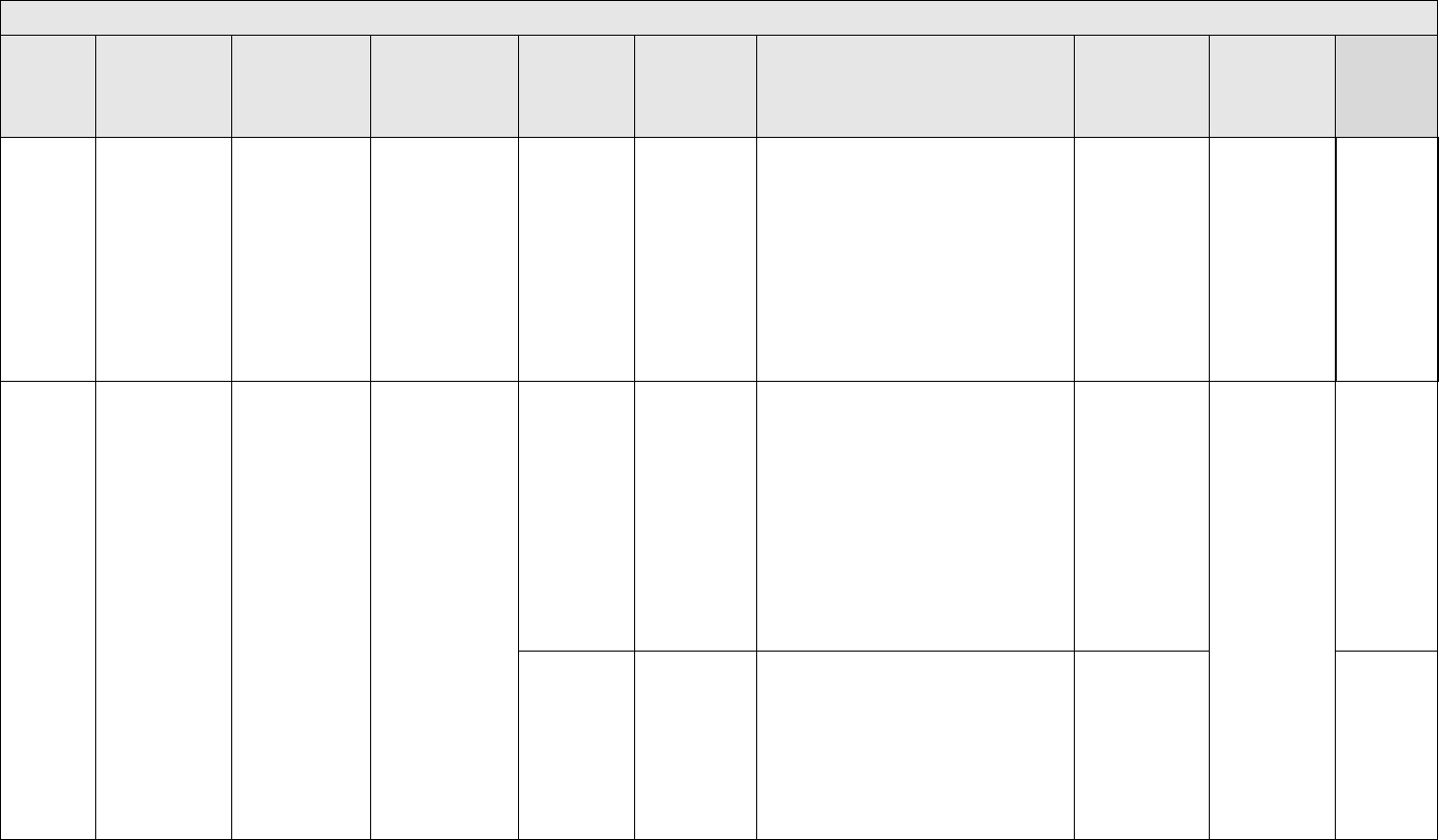
APPROVED FOR PUBLIC RELEASE
85
Top Level Failure Modes
Failure
Mode ID
Failure Mode
Description
Discussion/
Example of Failure
Mode
Tailoring
Recommendation
Common
Defect
Enumeration
Description
Detectability Level
Skill /
Effort required by
SFMEA analysts
Applicability
Reference
failed because the
command for the
main engine cutoff
was missing.
TL-FC-1-C-1
The required
feature is
specified but
code isn't
written to
implement it.
2 -Failure mode will be detected via testing of a
written requirement
Medium - The
FMEA analyst
needs to read the
test procedures to
ensure this was
tested
Neufelder
2021
Section 3.1,
3.2.2
Missing
function;
Kaner/Faulk/
Nguyen
page 365
TL-FC-2
(continued
on next
page)
TL-FC-2
(cont.)
A crucially
important detail is
missing from the
entire set of
specifications
Overly general
requirements is a
common problem
in every industry.
The software
engineers have
too many options
for implementing
the requirements
and hence may
guess at a solution
that isn't what the
customer wants.
All software
systems
TL-FC-2-S-1
The crucially
important detail
is missing from
the specification
5 - This won't be detected in any test
Medium -
Understanding
what is "missing"
requires
knowledge of the
system
All mission
critical systems
BEIZER
Bugs in
Perspective
3.2.1
Incomplete
specification,
ambiguous
specification
TL-FC-2-C-1
The
specification is
detailed but the
code doesn't
implement the
entire
specification
2 - Failure mode will be detected via testing of a
written requirement
Medium - The
FMEA analyst
needs to read the
test procedures to
ensure this was
tested
Neufelder
2021
Section 3.1

APPROVED FOR PUBLIC RELEASE
86
Top Level Failure Modes
Failure
Mode ID
Failure Mode
Description
Discussion/
Example of Failure
Mode
Tailoring
Recommendation
Common
Defect
Enumeration
Description
Detectability Level
Skill /
Effort required by
SFMEA analysts
Applicability
Reference
TL-FC-3
(continued
next page)
The software
cannot
accommodate a
full range of input
trajectories
An input trajectory
is not just the
range of inputs but
the time sequence
of inputs. Ex: A fin
on a missile must
move from one
angular position to
another. The
trajectories are the
sequence of
movements over
the flight.
All software
systems
TL-FC-3-S-1
There are no
requirements to
consider or test
the trajectories.
4 - This requires trajectory testing which is not
part of requirements testing
Medium -
Understanding
what is "missing"
requires
knowledge of the
system
All mission
critical systems
BEIZER
Bugs in
Perspective
3.2.1
Incomplete
specification,
ambiguous
specification
TL-FC-3-C-1
There are
requirements
for trajectories
and testing
them but the
software
doesn't comply.
2 - Failure mode will be detected via testing of a
written requirement
Medium - The
FMEA analyst
needs to read the
test procedures to
ensure this was
tested
Neufelder
2021
Section 3.1
TL-FC-4
(continued
next page)
The software is
unable to operate
with a change in
mission distance
or time
Ex: A system used
to have a mission
time of X hours
and now has a
mission time of
X+Y hours. The
software may not
work as required
with the new
mission time.
Any system that has
recently been
modified to have a
change in mission
time
TL-FC-4-S-1
Even though
the system
requirement
has the new
mission time
there is no
software
requirement for
the new mission
time
4 - Since there is no specification this won't be
identified in testing
Low - The
specifications
either discuss this
or they don't
Any existing
system that has
a new mission
time
Neufelder
2021
Section 3.1

APPROVED FOR PUBLIC RELEASE
87
Top Level Failure Modes
Failure
Mode ID
Failure Mode
Description
Discussion/
Example of Failure
Mode
Tailoring
Recommendation
Common
Defect
Enumeration
Description
Detectability Level
Skill /
Effort required by
SFMEA analysts
Applicability
Reference
TL-FC-4
(cont.)
TL-FC-4-C-1
There is a clear
software
requirement for
the new mission
time but the
software has
hard coded
constants that
prevent
operating for
the new time
2-Failure mode will be detected via testing of a
written requirement
Medium - the
FMEA analyst
needs to read the
test procedures to
ensure this was
tested
TL-FC-4-C-2
There is a clear
software
requirement for
the new mission
time but the
software has
data sizes that
are too small for
the new mission
time
2-Failure mode will be detected via testing of a
written requirement
Medium - the
FMEA analyst
needs to read the
test procedures to
ensure this was
tested
Example #2: An
aircraft used to
have a distance of
500 miles. Now it
has a distance of
1000 miles.
Any system that has
recently been
modified to have a
change in mission
distance
TL-FC-4-S-2
Even though
the system
requirement
has the new
mission
distance there
is no software
requirement for
the new mission
distance
4 - Since there is no specification this won't be
identified in testing
Low - The
specifications
either discuss this
or they don't
Any existing
system that has
a new mission
distance
Neufelder
2021
Section 3.1
TL-FC-4-C-3
There is a clear
software
requirement for
the new mission
distance but the
software has
hard coded
constants that
prevent
operating for
the new
distance
2 - Failure mode will be detected via testing of a
written requirement
Medium - The
FMEA analyst
needs to read the
test procedures to
ensure this was
tested

APPROVED FOR PUBLIC RELEASE
88
Top Level Failure Modes
Failure
Mode ID
Failure Mode
Description
Discussion/
Example of Failure
Mode
Tailoring
Recommendation
Common
Defect
Enumeration
Description
Detectability Level
Skill /
Effort required by
SFMEA analysts
Applicability
Reference
TL-FC-4
(cont.)
TL-FC-4-C-4
There is a clear
software
requirement for
the new mission
distance but the
software has
data sizes that
are too small for
the new mission
distance
2 - Failure mode will be detected via testing of a
written requirement
Medium - The
FMEA analyst
needs to read the
test procedures to
ensure this was
tested
Example #3: The
payload or weight
of the system or
weapon will
change. The
ARIANE 5
exploded due to a
heavier payload
that stressed the
velocity
computations in a
way that was
different than
ARIANE 4.
Any system that has
recently been
modified to have a
change in mission
payload
TL-FC-4-S-3
Even though
there is a
change in
payload or
weapon weight
there is no
software
requirement for
this change
4 - Since there is no specification this won't be
identified in testing
Low - The
specifications
either discuss this
or they don't
Any weapon or
system with a
changed
payload or
weight
Neufelder
2021
Section 3.1
TL-FC-4-C-5
There is a clear
software
requirement for
the new weight
but the software
has hard coded
constants that
prevent
operating for
the new weight
2 - Failure mode will be detected via testing of a
written requirement
Medium - The
FMEA analyst
needs to read the
test procedures to
ensure this was
tested
TL-FC-4-C-6
There is a clear
software
requirement for
the new weight
but the software
has data sizes
that are too
small for the
new weight
2 - Failure mode will be detected via testing of a
written requirement
Medium - The
FMEA analyst
needs to read the
test procedures to
ensure this was
tested

APPROVED FOR PUBLIC RELEASE
89
Top Level Failure Modes
Failure
Mode ID
Failure Mode
Description
Discussion/
Example of Failure
Mode
Tailoring
Recommendation
Common
Defect
Enumeration
Description
Detectability Level
Skill /
Effort required by
SFMEA analysts
Applicability
Reference
TL-FC-5
The software fails
to achieve it's
required goal.
Ex: The Denver
Airport software
had exactly one
goal - to reduce
the time it takes to
get the bags onto
the aircraft. The
software actually
caused the time to
get the bags on
the aircraft to be
longer than not
using any software
at all. That's
because the
software assumed
that the bags
would be perfectly
placed onto the
luggage system
and would never
fall off the luggage
system. The
software
requirements
should have had
one performance
requirement to
measure the time
it takes for the
bags to get to the
aircraft with normal
operation by
imperfect humans.
All software
systems
TL-FC-5-S-1
The
specifications
are missing
explicit
requirements to
ensure that the
software meets
the top level
objective with
normal
operating
conditions.
This is often a
performance
requirement.
4 - Since there is no specification this won't be
identified in testing
Low - The
specifications
either discuss this
or they don't
All mission
critical systems
but particularly
concerning for
new systems
that are
relatively large
and complex
Neufelder
2021
Section 3.1
TL-FC-5-C-1
The
specifications
have explicit
requirements to
ensure that the
software meets
the top level
objective but
the software
doesn't meet
the
requirement.
2 -Failure mode will be detected via testing of a
written requirement
Medium - The
FMEA analyst
needs to read the
test procedures to
ensure this was
tested
TL-FC-6
(continued
next page)
There is no data
logging and there
should be
Mission critical
systems need data
logging for fault
isolation and
support of the
field.
Any mission critical
software system
TL-FC-6-S-1
There are no
specifications
for data logging
4 - Since there is no specification this won't be
identified in testing
Low - The
specifications
either discuss this
or they don't
All mission
critical systems.
Note that this is
typically required
for safety critical
systems.
JSSSEH
Appendix E

APPROVED FOR PUBLIC RELEASE
90
Top Level Failure Modes
Failure
Mode ID
Failure Mode
Description
Discussion/
Example of Failure
Mode
Tailoring
Recommendation
Common
Defect
Enumeration
Description
Detectability Level
Skill /
Effort required by
SFMEA analysts
Applicability
Reference
TL-FC-6
(cont.)
TL-FC-6-S-2
The
specifications
for data logging
are overly
general and
don't require
logging of
sufficient detail
for warfighters
5 - If the specifications are themselves faulty it
won't be identified in testing
Low - The
specifications
either discuss this
or they don't
TL-FC-6-C-1
There are
sufficient
specifications
for data logging
but the software
doesn't meet
the
specifications
2 - Failure mode will be detected via testing of a
written requirement
Medium - The
FMEA analyst
needs to read the
test procedures to
ensure this was
tested
TL-FC-7
(continued
on next
page)
BIT software
interferes with
operational
execution
BIT software can
and will effect
operations. If it is
executed at the
wrong time or
wrong phase it can
cause the software
to fail to perform
it's job.
Applicable for any
software that has
Power On Self Test
or Bit In Test or
Continuous BIT or
Periodic BIT
TL-FC-7-S-1
There are no
specifications
prohibiting
when BIT
cannot be run
4 - Since there is no specification this won't be
identified in testing
Low - The
specifications
either discuss this
or they don't
All mission
critical systems.
Note that this is
typically required
for safety critical
systems.
TL-FC-7-S-2
There are
specifications
for when BIT
cannot be run
but the
specifications
are incorrect
(i.e. it has the
wrong BIT
running at the
wrong time)
5 - If the specifications are themselves faulty it
won't be identified in testing
Low - The
specifications
either discuss this
or they don't
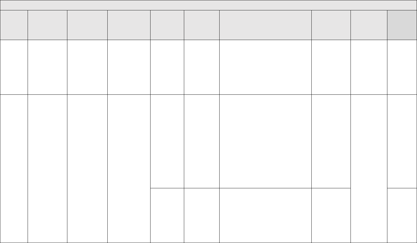
APPROVED FOR PUBLIC RELEASE
91
Top Level Failure Modes
Failure
Mode ID
Failure Mode
Description
Discussion/
Example of Failure
Mode
Tailoring
Recommendation
Common
Defect
Enumeration
Description
Detectability Level
Skill /
Effort required by
SFMEA analysts
Applicability
Reference
TL-FC-7
(cont.)
TL-FC-7-C-1
There are
specifications
for when BIT
cannot be run
but the code
executes BIT at
the wrong time
or mode
anyhow
2-Failure mode will be detected via testing of a
written requirement
Medium - the
FMEA analyst
needs to read the
test procedures to
ensure this was
tested
TL-PR- 1
Software loses
accuracy after
extended duration
with no reboot
Software doesn't
wear out but it can
experience a
degradation in
performance due
to timing and data
inaccuracies that
accumulate.
Any system that is
on for more than a
few minutes or
hours without
rebooting
TL-PR-1-S-1
The
specifications
don't include a
performance
specification for
the software to
be tested 1.5
times the
longest mission.
The tests must
explicitly check
for accuracy of
data and timing
at start of
mission and
compare to end
of mission.
5 - This requires running the software without
reboot for a long time which is typically not done
Highly
recommended for
all mission critical
systems. This is
required by the
JSSSEH for
safety critical
software. It can
also cause
mission failures.
All mission
critical systems.
Note that this is
typically required
for safety critical
systems.
JSSSEH
Appendix
E.3.15
TL-PR-1-C-1
The
specification for
endurance
testing exists
but the software
doesn't meet it.
2 - Failure mode will be detected via testing of a
written requirement
Medium – The
FMEA analyst
needs to read the
test procedures to
ensure this was
tested
JSSSEH
Appendix
E.3.15

APPROVED FOR PUBLIC RELEASE
92
Top Level Failure Modes
Failure
Mode ID
Failure Mode
Description
Discussion/
Example of Failure
Mode
Tailoring
Recommendation
Common
Defect
Enumeration
Description
Detectability Level
Skill /
Effort required by
SFMEA analysts
Applicability
Reference
TL-PR-2
Software is
unable to execute
after extended
duration with no
reboot
Software doesn't
wear out but it can
experience a
degradation in
performance due
to memory faults.
Any system that is
on for more than a
few minutes or
hours without
rebooting
TL-PR-2-S-1
There is an
explicit
performance
specification for
testing 1.5
times longest
mission time.
5 - This requires running the software without
reboot for a long time which is typically not done
Low - The
specifications
either discuss this
or they don't
All mission
critical systems.
Note that this is
typically required
for safety critical
systems.
JSSSEH
Appendix
E.3.15
TL-PR-2-C-1
The
specification for
endurance
testing exists
but the software
doesn't meet it.
2 - Failure mode will be detected via testing of a
written requirement
Medium - The
FMEA analyst
needs to read the
test procedures to
ensure this was
tested
JSSSEH
Appendix
E.3.15
TL-PR-3
(continued
next page)
Software is
unable to execute
due to build up of
files
The NASA spirit
rover is just one
example of what
happens when
files such as log
files accumulate
and then cause
the system to run
out of disk space
in the middle of a
mission.
Any system that has
any files that grow
in size. Log files,
database files,
video files, audio
files, etc.
TL-PR-3-S-1
There are no
specifications to
detect build up
of log files (i.e.
requirements
for rollover)
5 - There is no specification and this requires
fault injection testing to identify
Low - The
specifications
either discuss this
or they don't
Any system
which has data
logging
Neufelder
2021
Section 3.1
TL-PR-3-C-1
There are
specifications to
handle build up
of log files but
the code
doesn't work as
specified
2 - Failure mode will be detected via testing of a
written requirement
Medium - The
FMEA analyst
needs to read the
test procedures to
ensure this was
tested
Neufelder
2021
Section 3.1

APPROVED FOR PUBLIC RELEASE
93
Top Level Failure Modes
Failure
Mode ID
Failure Mode
Description
Discussion/
Example of Failure
Mode
Tailoring
Recommendation
Common
Defect
Enumeration
Description
Detectability Level
Skill /
Effort required by
SFMEA analysts
Applicability
Reference
TL-PR- 3
(cont.)
TL-PR-3-S-2
There are no
specifications to
detect build up
of media files
such videos,
audio, etc. (i.e.
requirements
for rollover)
5 - There is no specification and this requires
fault injection testing to identify
Low - The
specifications
either discuss this
or they don't
Any system
which has media
files
Neufelder
2021
Section 3.1
TL-PR-3-C-2
There are
specifications to
handle build up
of media files
but the code
doesn't work as
specified
2 - Failure mode will be detected via testing of a
written requirement
Medium - The
FMEA analyst
needs to read the
test procedures to
ensure this was
tested
Neufelder
2021
Section 3.1
TL-PR-3-S-3
There are no
specifications to
detect build up
of database
files (i.e.
requirements
for ask the user
to purge old
data)
5 - There is no specification and this requires
fault injection testing to identify
Low - The
specifications
either discuss this
or they don't
Any system that
has a database
Neufelder
2021
Section 3.1
TL-PR-3-C-3
There are
specifications to
handle build up
of database
files but the
code doesn't
work as
specified
2 -Failure mode will be detected via testing of a
written requirement
Medium - The
FMEA analyst
needs to read the
test procedures to
ensure this was
tested
Neufelder
2021
Section 3.1

APPROVED FOR PUBLIC RELEASE
94
Top Level Failure Modes
Failure
Mode ID
Failure Mode
Description
Discussion/
Example of Failure
Mode
Tailoring
Recommendation
Common
Defect
Enumeration
Description
Detectability Level
Skill /
Effort required by
SFMEA analysts
Applicability
Reference
TL-PR- 4
(continued
next page)
Data logging files
are overwritten
before they can
be read by a user
Rolling over files is
a mitigation for
failure mode PR-3.
Unfortunately
sometimes the
rollover may be
too frequent and
overwrite data
before it can be
read or used by
the user.
Any system that has
a data logging
feature. This could
include systems
with video or audio
recording.
TL-PR-4-S-1
There are no
requirements
for rolling over
of log files to
ensure that a
specific number
of hours or
missions can be
captured
5 - There is no specification and this requires
running for an extended period of time
Low - The
specifications
either discuss this
or they don't
Any system
which is required
to have data
logging
Neufelder
2021
Section 3.1
TL-PR-4-C-1
The
requirements
for rollover of
log files are
sufficient but
the code rolls
over the files
too frequently
2-Failure mode will be detected via testing of a
written requirement
Medium - the
FMEA analyst
needs to read the
test procedures to
ensure this was
tested
Neufelder
2021
Section 3.1
TL-PR-4-S-2
There are no
requirements
for rolling over
of media files to
ensure that a
specific number
of hours or
missions can be
captured
5 - There is no specification and this requires
running for an extended period of time
Low - The
specifications
either discuss this
or they don't
Any system
which is required
to have media
recordings
Neufelder
2021
Section 3.1
TL-PR-4-C-2
The
requirements
for rollover of
media files are
sufficient but
the code rolls
over the files
too frequently
2-Failure mode will be detected via testing of a
written requirement
Medium - the
FMEA analyst
needs to read the
test procedures to
ensure this was
tested
Neufelder
2021
Section 3.1

APPROVED FOR PUBLIC RELEASE
95
Top Level Failure Modes
Failure
Mode ID
Failure Mode
Description
Discussion/
Example of Failure
Mode
Tailoring
Recommendation
Common
Defect
Enumeration
Description
Detectability Level
Skill /
Effort required by
SFMEA analysts
Applicability
Reference
TL-PR- 4
(cont.)
TL-PR-4-S-3
There are no
requirements to
prompt the user
when database
files are getting
too large but
the prompting
happens before
the database
files are really
too large.
5 - There is no specification and this requires
running for an extended period of time
Low - The
specifications
either discuss this
or they don't
Any system
which is required
to has a
database that
can continually
grow in size.
Neufelder
2021
Section 3.1
TL-PR-4-C-3
The
requirements
are clear but
the software still
prompts for
large database
files too early.
2-Failure mode will be detected via testing of a
written requirement
Medium - the
FMEA analyst
needs to read the
test procedures to
ensure this was
tested
Neufelder
2021
Section 3.1
TL-PR-5
(continued
on next
page)
Software
degrades or stops
working with
maximum
concurrent users
This failure mode
has effected many
commercial
systems because
software engineers
neglect to design
the system for
maximum
concurrent users.
Any system that has
multiple concurrent
users
TL-PR-5-S-1
There are no
requirements
for the software
to operate with
a specific
number of
maximum users
5 - There is no specification and this requires
running many concurrent users
Low - The
specifications
either discuss this
or they don't
Any multi-user
system
Neufelder
2021
Section 3.1
TL-PR-5-S-2
There are
requirements
for the software
to operate with
a specific
number of
maximum users
but that number
is too low to
support the
mission
5 - If the specifications are themselves faulty it
won't be identified in testing
Low - The
specifications
either discuss this
or they don't
Neufelder
2021
Section 3.1

APPROVED FOR PUBLIC RELEASE
96
Top Level Failure Modes
Failure
Mode ID
Failure Mode
Description
Discussion/
Example of Failure
Mode
Tailoring
Recommendation
Common
Defect
Enumeration
Description
Detectability Level
Skill /
Effort required by
SFMEA analysts
Applicability
Reference
TL-PR-5
(cont.)
TL-PR-5-C-1
There are
requirements
for maximum
users but the
software
doesn't meet
the
requirements
2-Failure mode will be detected via testing of a
written requirement
Medium - the
FMEA analyst
needs to read the
test procedures to
ensure this was
tested
Neufelder
2021
Section 3.1
TL-PR-6
Software
degrades with
many rapid
operations
Example of rapid
operations: A
driverless vehicle
starts and stops,
starts and stops,
starts and stops.
Example 2: A
weapon handles
engagements in
rapid succession
Any software
system
TL-PR-6-S-1
There are no
requirements
for testing the
software to
ensure that it
can handle a
rapid successful
of
engagements.
5 - There is no specification and this requires
peak loading testing which is not part of
requirements testing
Low - The
specifications
either discuss this
or they don't
All mission
critical systems
Neufelder
2021
Section 3.1
TL-PR-6-C-1
The is a
requirement but
the software
doesn't meet it
2-Failure mode will be detected via testing of a
written requirement
Medium - the
FMEA analyst
needs to read the
test procedures to
ensure this was
tested
Neufelder
2021
Section 3.1

APPROVED FOR PUBLIC RELEASE
97
Top Level Failure Modes
Failure
Mode ID
Failure Mode
Description
Discussion/
Example of Failure
Mode
Tailoring
Recommendation
Common
Defect
Enumeration
Description
Detectability Level
Skill /
Effort required by
SFMEA analysts
Applicability
Reference
TL-PR-7
(continued
next page)
TL-PR-7
(cont.)
Software
degrades with
simultaneous
threats, targets,
objects, inputs or
requests
Example: An IFF
can identify one
threat at a time but
not more than one
at the same time
Any system that is
doing threat
detection, target
tracking, image
recognition
TL-PR-7-S-1
There are no
requirements
for testing the
software to
ensure that it
can handle
simultaneous
threats, targets,
objects or
inputs
5 - There is no specification and this requires
peak loading testing which is not part of
requirements testing
Low - The
specifications
either discuss this
or they don't
Sensors,
driverless
systems
Neufelder
2021
Section 3.1
TL-PR-7-C-1
The is a
requirement but
the software
doesn't meet it
2-Failure mode will be detected via testing of a
written requirement
Medium - the
FMEA analyst
needs to read the
test procedures to
ensure this was
tested
Neufelder
2021
Section 3.1
TL-PR-8
Software
degrades with
different threats,
targets, objects,
inputs, requests
Example: An IFF
can identify
multiple concurrent
threats but not
when they are of
different types
Any system that is
doing threat
detection, target
tracking, image
recognition
TL-PR-8-C-1
There are no
requirements
for testing the
software to
ensure that it
can handle
multiple
concurrent
threats, objects,
targets, inputs
of different
types
5 - There is no specification and this requires
peak loading testing which is not part of
requirements testing
Low - The
specifications
either discuss this
or they don't
Sensors,
driverless
systems
Neufelder
2021
Section 3.1

APPROVED FOR PUBLIC RELEASE
98
Top Level Failure Modes
Failure
Mode ID
Failure Mode
Description
Discussion/
Example of Failure
Mode
Tailoring
Recommendation
Common
Defect
Enumeration
Description
Detectability Level
Skill /
Effort required by
SFMEA analysts
Applicability
Reference
TL-PR-8-C-1
The is a
requirement but
the software
doesn't meet it
2-Failure mode will be detected via testing of a
written requirement
Medium - the
FMEA analyst
needs to read the
test procedures to
ensure this was
tested
Neufelder
2021
Section 3.1
TL-T-1
(continued
on next
page)
TL-T-1
(cont.)
Initialization time
is too long to
accommodate
uptime
requirements
Example: A
system must be up
for 23 hours per
day. However, the
software takes 45
minutes to initialize
and 30 minutes to
set up. The system
must be serviced
once per day so it
is guaranteed to
not make uptime
requirements.
Any software
system
TL-T-1-S-1
There is no
explicit
requirements
for the software
initialization
time
5 - There is no specification and testers rarely
notice how long it takes to initialize a system
Low - The
specifications
either discuss this
or they don't
All mission
critical systems
Neufelder
2021
Section 3.1
TL-T-1-S-2
There is a
requirement for
the software
initialization
time but it is too
long to meet the
overall system
availability
requirement
5 - If the specifications are themselves faulty it
won't be identified in testing
Low - The
specifications
either discuss this
or they don't
Neufelder
2021
Section 3.1
TL-T-1-C-1
There are
sufficient
requirements
for initialization
time but the
software
doesn't meet
them
2-Failure mode will be detected via testing of a
written requirement
Medium - the
FMEA analyst
needs to read the
test procedures to
ensure this was
tested
Neufelder
2021
Section 3.1.
,
Kaner/Faulk/
Nguyen
page 368
Slow
program

APPROVED FOR PUBLIC RELEASE
99
Top Level Failure Modes
Failure
Mode ID
Failure Mode
Description
Discussion/
Example of Failure
Mode
Tailoring
Recommendation
Common
Defect
Enumeration
Description
Detectability Level
Skill /
Effort required by
SFMEA analysts
Applicability
Reference
TL-T-2
The combined
total of the restart
times is too long
to accommodate
uptime
requirements
Example: A
system must be up
for 22 hours per
day for a 4 day
mission. It doesn't
need servicing
during the 4 day
mission. However,
the software takes
45 minutes to
initialize and 30
minutes to set up
every time it
reboots. If the
software has to
reboot more than
once per day the
availability won't
be met.
Any software
system
TL-T-2-S-1
There are no
requirements
for the software
to meet a
minimum
uptime per day
over the entire
mission which
apply to all
combined
interruptions
and not just
each
interruption.
5 - There is no specification and testers rarely
notice how long it takes to reboot a system
Low - The
specifications
either discuss this
or they don't
All mission
critical systems
Neufelder
2021
Section 3.1
TL-T-2-C-1
There are
requirements
but the software
doesn't meet
them
2-Failure mode will be detected via testing of a
written requirement
Medium - the
FMEA analyst
needs to read the
test procedures to
ensure this was
tested
Neufelder
2021
Section 3.1
TL-T-3
Any manual
action takes too
long to
accommodate the
uptime
requirements
Example: A
system must be up
for 23 hours per
day. The user
must set up the
system after it
initializes which
takes 45 minutes.
They are unable to
do that within 15
minutes.
Any software
system with an end
user
TL-T-3-S-1
There are no
timing
requirements
for manual
operations.
5- There is no specification and test engineers
rarely notice how long it takes to do any manual
action
Low - The
specifications
either discuss this
or they don't
All mission
critical systems
Neufelder
2021
Section 3.1

APPROVED FOR PUBLIC RELEASE
100
Top Level Failure Modes
Failure
Mode ID
Failure Mode
Description
Discussion/
Example of Failure
Mode
Tailoring
Recommendation
Common
Defect
Enumeration
Description
Detectability Level
Skill /
Effort required by
SFMEA analysts
Applicability
Reference
TL-T-3-C-1
There are
requirements
but the user
can't meet them
2-Failure mode will be detected via testing of a
written requirement
Medium - the
FMEA analyst
needs to read the
test procedures to
ensure this was
tested
Neufelder
2021
Section 3.1
TL-T-4
The time to safely
shutdown the
software after a
mission exceeds
the time required
for required
mission uptime
Example: A
system has a 4
day mission and
has timing
requirements for
transport between
missions. The
software must be
shut down properly
in order to work for
the next mission.
The shutdown time
takes longer than
the transport time
allows.
Any software
system
TL-T-4-S-1
There are no
timing
requirements
for shutdown
5 - There is no specification and testers rarely
notice how long it takes to shut down the
system
Low - The
specifications
either discuss this
or they don't
All systems that
are transported
between
missions
Neufelder
2021
Section 3.1
TL-T-4-C-1
There are
requirements
but the software
doesn't meet
them
2-Failure mode will be detected via testing of a
written requirement
Medium - the
FMEA analyst
needs to read the
test procedures to
ensure this was
tested
Neufelder
2021
Section 3.1
TL-T-5
Watchdog
timers/heartbeats
are missing
This is required for
safety critical
software and is all
important for
mission critical
software
Any software
system can have a
WDT. The systems
that have mission
critical timing
requirements
typically need this.
TL-T-5-S-1
There are no
requirements
for a WDT or
heartbeat
5- This won't be tested without a requirement
Low - The
specifications
either discuss this
or they don't
All mission
critical systems
JSSSEH
Appendix E

APPROVED FOR PUBLIC RELEASE
101
Top Level Failure Modes
Failure
Mode ID
Failure Mode
Description
Discussion/
Example of Failure
Mode
Tailoring
Recommendation
Common
Defect
Enumeration
Description
Detectability Level
Skill /
Effort required by
SFMEA analysts
Applicability
Reference
TL-T-5-C-1
There are
requirements
but the software
doesn't meet
them
2-Failure mode will be detected via testing of a
written requirement
Medium - the
FMEA analyst
needs to read the
test procedures to
ensure this was
tested
JSSSEH
Appendix E
TL-T-6
Schedulability
exceeds required
maximum
If the
schedulability
requirements
aren't met, critical
commands could
get dropped
Any multi-threaded
software
TL-T-6-S-1
There are no
specific
requirements
for
schedulability
5- This won't be tested without a requirement
Low - The
specifications
either discuss this
or they don't
All mission
critical systems
Neufelder
2021
Section 3.1
TL-T-6-C-1
There are
requirements
but the software
doesn't meet
them
2-Failure mode will be detected via testing of a
written requirement
Medium - the
FMEA analysts
needs to request
and analyze
schedulability
diagrams and
then assess the
test procedures
Neufelder
2021
Section 3.1
TL-T-7
(continued
next page)
Continuous
monitoring is too
frequent
If the monitoring is
too frequent it will
interrupt normal
operations
Any software
system
TL-T-7-S-1
The frequency
isn't specifically
identified (i.e.
use of words
like periodically
instead of a
number)
5- This won't be tested without a requirement
Low - The
specifications
either discuss this
or they don't
All mission
critical systems
Neufelder
2021
Section 3.1

APPROVED FOR PUBLIC RELEASE
102
Top Level Failure Modes
Failure
Mode ID
Failure Mode
Description
Discussion/
Example of Failure
Mode
Tailoring
Recommendation
Common
Defect
Enumeration
Description
Detectability Level
Skill /
Effort required by
SFMEA analysts
Applicability
Reference
TL-T-7
(cont.)
TL-T-7-S-2
There is a
defined
specification but
it's too often
5 - If the specifications are themselves faulty it
won't be identified in testing
Medium - the
FMEA analysts
needs to request
that the design
engineers provide
justification for
CM period
Neufelder
2021
Section 3.1
TL-T-7-C-1
There are
requirements
but the software
doesn't meet
them
2-Failure mode will be detected via testing of a
written requirement
Medium - the
FMEA analyst
needs to read the
test procedures to
ensure this was
tested
Neufelder
2021
Section 3.1
TL-T-8
(continued
next page)
Continuous
monitoring is not
frequent enough
If the monitoring
isn't frequent
enough it won't
detect critical
faults
Any software
system
TL-T-8-S-1
The frequency
isn't specifically
identified (i.e.
use of words
like periodically
instead of a
number)
5- This won't be tested without a requirement
Low - The
specifications
either discuss this
or they don't
All mission
critical systems
Neufelder
2021
Section 3.1
TL-T-8-S-2
There is a
defined
specification but
it's not often
enough
5 - If the specifications are themselves faulty it
won't be identified in testing
Medium - the
FMEA analysts
needs to request
that the design
engineers provide
justification for
CM period
Neufelder
2021
Section 3.1

APPROVED FOR PUBLIC RELEASE
103
Top Level Failure Modes
Failure
Mode ID
Failure Mode
Description
Discussion/
Example of Failure
Mode
Tailoring
Recommendation
Common
Defect
Enumeration
Description
Detectability Level
Skill /
Effort required by
SFMEA analysts
Applicability
Reference
TL-T-8
(cont.)
TL-T-8-C-1
There are
requirements
but the software
doesn't meet
them
2-Failure mode will be detected via testing of a
written requirement
Medium - the
FMEA analyst
needs to read the
test procedures to
ensure this was
tested
Neufelder
2021
Section 3.1
TL-U-1
Software
assumes that the
user is always
looking the user
interface
Ex: The software
controlling a CT
scan generates
critical warnings
on the display
when the caregiver
is helping the
patient get into the
CT scan.
Any software with a
user interface
TL-U-1-S-1
There are no
requirements
for
communicating
critical alerts to
the user when
they aren't
watching the
software UI
5- This won't be tested without a requirement as
it requires knowledge of the end user
Low - The
specifications
either discuss this
or they don't
Any system with
a user interface
Neufelder
2021
Section 3.1
TL-U-1-C-1
There are
requirements
but the software
doesn't meet
them
2-Failure mode will be detected via testing of a
written requirement
Medium - the
FMEA analyst
needs to read the
test procedures to
ensure this was
tested
Neufelder
2021
Section 3.1
TL-U-2
(continued
next page)
The user interface
has a paradigm
that doesn't fit
with generation of
users using the
system
Ex: Warfighters
are largely
generation Z and
millennials.
However the
software interface
was written by
baby boomers for
baby boomers.
The warfighters
are expecting to
Any software with a
user interface
TL-U-2-S-1
There are no
requirements
for modern user
interface
paradigms
consistent with
the generation
of warfighters
5- This won't be tested without a requirement as
it requires knowledge of the end user
Medium -
Someone familiar
with human
factors typically
can make this
assessment.
Any system with
a user interface
Neufelder
2021
Section 3.1

APPROVED FOR PUBLIC RELEASE
104
Top Level Failure Modes
Failure
Mode ID
Failure Mode
Description
Discussion/
Example of Failure
Mode
Tailoring
Recommendation
Common
Defect
Enumeration
Description
Detectability Level
Skill /
Effort required by
SFMEA analysts
Applicability
Reference
TL-U-2
(cont.)
be able to pinch
and zoom. The
software crashes
when they try to do
that.
TL-U-2-C-1
There are
requirements
but the software
doesn't meet
them
2-Failure mode will be detected via testing of a
written requirement
Medium - the
FMEA analyst
needs to read the
test procedures to
ensure this was
tested
Neufelder
2021
Section 3.1
TL-U-3
The software
requires the user
to handle faults
when in fact the
faults cannot be
fixed by the user
The software
should only require
the user to
address faults that
they have the
capability to
address. Users
cannot fix
algorithm or data
faults for example.
They can fix
hardware that's
faulted.
Any software with a
user interface
TL-U-3-S-1
There are no
requirements
for the software
to log and/or
heal any faults
that the user
cannot address.
5- This won't be tested without a requirement as
it requires knowledge of the end user
Low - The
specifications
either discuss this
or they don't
Any system with
a user interface
Neufelder
2021
Section 3.1
TL-U-3-C-1
There are
requirements
but the software
doesn't meet
them
2-Failure mode will be detected via testing of a
written requirement
Medium - the
FMEA analyst
needs to read the
test procedures to
ensure this was
tested
Neufelder
2021
Section 3.1
TL-U-4
(continued
next page)
The software
floods the user
with too many
concurrent error
messages
The software
should attempt to
combine or pool
related error
messages so that
the user isn't
flooded. Ex: An
import file has 50
rows of data with
the same data
entry problem.
Instead of
displaying the
Any software with a
user interface
TL-U-4-S-1
There are no
requirements
for the software
to pool or
combine error
messages
particularly
when importing
data
5- This won't be tested without a requirement as
it requires fault injection of multiple faults
Low - The
specifications
either discuss this
or they don't
Any system with
a user interface
Neufelder
2021
Section 3.1

APPROVED FOR PUBLIC RELEASE
105
Top Level Failure Modes
Failure
Mode ID
Failure Mode
Description
Discussion/
Example of Failure
Mode
Tailoring
Recommendation
Common
Defect
Enumeration
Description
Detectability Level
Skill /
Effort required by
SFMEA analysts
Applicability
Reference
TL-U-4
(cont.)
same message 50
times, generate
one message that
end of import
showing all rows
with bad data.
TL-U-4-C-1
There are
requirements
but the software
doesn't meet
them
2-Failure mode will be detected via testing of a
written requirement
Medium - the
FMEA analyst
needs to read the
test procedures to
ensure this was
tested
Neufelder
2021
Section 3.1
TL-U-5
The software fails
to identify the
urgency of the
error message
If non essential
error message are
mixed with
essential error
messages the user
may ignore all of
them
Any software with a
user interface
TL-U-5-S-1
There are no
requirements
for error
messages to be
prioritized by
urgency
5- Without a requirement, the software tester
won't notice the urgency of the message
Low - The
specifications
either discuss this
or they don't
Any system with
a user interface
that requires
quick reaction
from the
warfighter. Note
that this is
typically required
for safety critical
systems.
JSSSEH
Appendix
E.9.6, e.9.7,
e.9.8
TL-U-5-C-1
There are
requirements
but the software
doesn't meet
them
2-Failure mode will be detected via testing of a
written requirement
Medium - the
FMEA analyst
needs to read the
test procedures to
ensure this was
tested
JSSSEH
Appendix
E.9.6,e.9.7,
e.9.8,
Kaner/Faulk/
Nguyen
page 365
Failure to
identify the
source of the
error

APPROVED FOR PUBLIC RELEASE
106
Top Level Failure Modes
Failure
Mode ID
Failure Mode
Description
Discussion/
Example of Failure
Mode
Tailoring
Recommendation
Common
Defect
Enumeration
Description
Detectability Level
Skill /
Effort required by
SFMEA analysts
Applicability
Reference
TL-U-6
The software has
text entries when
other simpler
structures such as
pull down menus
suffice
Text entries are
problematic
because the inputs
have to be
checked for length
of input, type of
inputs, null entries,
special characters,
etc. These should
be reserved only
for input fields that
can't be replaced
with radio buttons
or pulldown
menus. Ex: Your
name and address
require a text
entry. A pulldown
menu is best for
your state.
Any software with a
user interface
TL-U-6-S-1
There are no
requirements to
use text entry
fields only when
radio buttons,
pulldown
menus and
checkboxes
aren't
appropriate.
5- Without a requirement, the software tester
won't assess whether there is a pull down menu
or text entry
Low - The
specifications
either discuss this
or they don't
Any system with
a user interface
Neufelder
2021
Section 3.1
TL-U-6-C-1
There are
requirements
but the software
engineers
ignored them
2-Failure mode will be detected via testing of a
written requirement
Medium - the
FMEA analyst
needs to read the
test procedures to
ensure this was
tested
Neufelder
2021
Section 3.1
TL-U-7
The software
allows data
overruns (i.e. The
user pressing the
enter key many
times in a rows)
This is a race
condition started
by the user. This
type of race
condition has been
associated with
serious software
failures.
Any software with a
user interface
TL-U-7-S-1
There are no
requirements to
ensure that the
user doesn’t
press the same
key (such as
return) many
times in a row
4- Since there is no requirement this won't get
tested
Low - The
specifications
either discuss this
or they don't
Any system with
a user interface.
Note that this is
typically required
for safety critical
systems.
JSSSEH
Appendix
E.13.7
TL-U-7-C-1
There is a
specification for
keyboard race
conditions but
the software
doesn't comply
with the spec
2-Failure mode will be detected via testing of a
written requirement
Medium - the
FMEA analyst
needs to read the
test procedures to
ensure this was
tested
JSSSEH
Appendix
E.13.7

APPROVED FOR PUBLIC RELEASE
107
Top Level Failure Modes
Failure
Mode ID
Failure Mode
Description
Discussion/
Example of Failure
Mode
Tailoring
Recommendation
Common
Defect
Enumeration
Description
Detectability Level
Skill /
Effort required by
SFMEA analysts
Applicability
Reference
TL-U-8
The software
allows the user to
type faster than
the input can be
recorded
This can lead to
undetected loss of
information.
Any software with a
user interface
TL-U-8-S-1
There are no
requirements to
ensure that the
user is
prevented from
typing faster
than the input
can be
recorded
4- Since there is no requirement this won't get
tested
Low - The
specifications
either discuss this
or they don't
Any system with
a user interface.
Note that this is
typically required
for safety critical
systems.
JSSSEH
Appendix
E.13.7
TL-U-8-S-1
There is a
specification to
prevent this
failure mode but
the software
doesn't comply
with the spec
2-Failure mode will be detected via testing of a
written requirement
Medium - the
FMEA analyst
needs to read the
test procedures to
ensure this was
tested
JSSSEH
Appendix
E.13.7
TL-U-9
The software fails
to provide positive
feedback when a
mission critical
function is
executed
Ex: Equipment that
provides radiation
therapy needs to
be able to advise
the practitioner
(who is in a
different room
during the therapy)
if the radiation was
emitted as per the
required
prescription
Any software with a
user interface
TL-U-9-S-1
There are no
requirements
for error
messages to be
prioritized by
urgency
5- Without a requirement, the software tester
won't assess whether there is feedback
Low - The
specifications
either discuss this
or they don't
Any system with
a user interface.
Note that this is
typically required
for safety critical
systems.
JSSSEH
Appendix
E.13.7
TL-U-9-C-1
There are
requirements
but the software
doesn't meet
them
2-Failure mode will be detected via testing of a
written requirement
Medium - the
FMEA analyst
needs to read the
test procedures to
ensure this was
tested
JSSSEH
Appendix
E.13.7

APPROVED FOR PUBLIC RELEASE
108
Top Level Failure Modes
Failure
Mode ID
Failure Mode
Description
Discussion/
Example of Failure
Mode
Tailoring
Recommendation
Common
Defect
Enumeration
Description
Detectability Level
Skill /
Effort required by
SFMEA analysts
Applicability
Reference
TL-U-10
The software fails
to advise the user
of an irreversible
event
Examples include
deleting files,
starting a launch
sequence, etc.
Any software with a
user interface
TL-U-10-S-1
There is no
specification to
advise the user
of an
irreversible
event
5- Without a requirement, the software tester
won't assess whether there is an advisement
Low - The
specifications
either discuss this
or they don't
Any system with
a user interface.
Note that this is
typically required
for safety critical
systems.
JSSSEH
Appendix
E.9.3
TL-U-10-C-1
There is a
specification to
prevent this
failure mode but
the software
does not
comply with the
spec
2-Failure mode will be detected via testing of a
written requirement
Medium - the
FMEA analyst
needs to read the
test procedures to
ensure this was
tested
JSSSEH
Appendix
E.9.3.
Kaner/Faulk/
Nguyen
page 365 -
Are you sure
for disaster
prevention
TL-U-11
(continued
next page)
The user
repeatedly makes
bad requests
The user
overloads the
system with bad
requests
Any software with a
user interface
TL-U-11-S-1
There is no
specification to
detect and
block users
making
repeated bad
requests
5- Without a requirement, the software tester
won't assess whether there is an advisement
Low - The
specifications
either discuss this
or they don't
Any system with
a user interface
Neufelder
2014 Table
3.3.2.1-1,
Microsoft
2022

APPROVED FOR PUBLIC RELEASE
109
Top Level Failure Modes
Failure
Mode ID
Failure Mode
Description
Discussion/
Example of Failure
Mode
Tailoring
Recommendation
Common
Defect
Enumeration
Description
Detectability Level
Skill /
Effort required by
SFMEA analysts
Applicability
Reference
TL-U-11
(cont.)
TL-U-11-C-1
There is a
specification to
prevent this
failure mode but
the software
does not
comply with the
spec
2-Failure mode will be detected via testing of a
written requirement
Medium - the
FMEA analyst
needs to read the
test procedures to
ensure this was
tested
TL-DD-1
High level
mismatches of
unit of measure
(i.e.
metric/English)
among software
LRUs.
High level means
that entire LRUs
are written in one
unit or the other
(See the Mars
Climate Orbiter).
Entire LRUs were
written in English
when Metric was
required for all
LRUS. This isn't
noticeable when
examining a single
LRU.
Any data interface
that represents a
unit of measure that
can be either metric
or English
TL-DD-1-S-1
There is no
overarching
interface spec
to define the
unit of measure
for ALL
software LRUS
For internal interfaces this is detectable with
requirements testing - 2. For external interfaces
this is 4.
Low - The
specifications
either discuss this
or they don't
Applicable for all
systems but is
most likely when
there are
software LRUS
developed by
multiple
contractors
Neufelder
2021
Section 3.1
TL-DD-1-C-1
There is an
overarching
specification but
one or more
contractor/LRU
ignored the
specification
For internal interfaces this is detectable with
requirements testing - 2. For external interfaces
this is 4.
Medium - the
FMEA analyst
needs to read the
test procedures to
ensure this was
tested
Neufelder
2021
Section 3.1

APPROVED FOR PUBLIC RELEASE
110
Top Level Failure Modes
Failure
Mode ID
Failure Mode
Description
Discussion/
Example of Failure
Mode
Tailoring
Recommendation
Common
Defect
Enumeration
Description
Detectability Level
Skill /
Effort required by
SFMEA analysts
Applicability
Reference
TL-DD-2
High level
mismatches of
unit of measure
(i.e.
radians/degrees)
among software
LRUs.
High level means
entire LRUs are
using radians
while others are
using degrees.
This isn't
noticeable when
examining
individual LRUS.
One must review
the units across
the LRUS to notice
the conflict.
Any data interface
that represents unit
of measure of
radians or degrees
TL-DD-2-S-1
There is no
overarching
interface spec
to define the
unit of measure
for ALL
software LRUS
For internal interfaces this is detectable with
requirements testing - 2. For external interfaces
this is 4.
Low - The
specifications
either discuss this
or they don't
Applicable for all
systems but is
most likely when
there are
software LRUS
developed by
multiple
contractors
Neufelder
2021
Section 3.1
TL-DD-2-C-1
There is an
overarching
specification but
one or more
contractor/LRU
ignored the
specification
For internal interfaces this is detectable with
requirements testing - 2. For external interfaces
this is 4.
Medium - the
FMEA analyst
needs to read the
test procedures to
ensure this was
tested
Neufelder
2021
Section 3.1
TL-DD-3
(continued
next page)
High level
mismatches of
unit of measure
(i.e. Clockwise
versus counter
clockwise) among
software LRUs.
High level means
entire LRUs are
using CW while
other LRUS are
using CCW. This
isn't noticeable
when examining
individual LRUS.
One
Any data interface
that represents
rotation of clockwise
or counterclockwise
TL-DD-3-S-1
There is no
overarching
interface spec
to define the
unit of measure
for ALL
software LRUS
For internal interfaces this is detectable with
requirements testing - 2. For external interfaces
this is 4.
Low - The
specifications
either discuss this
or they don't
Applicable for all
systems but is
most likely when
there are
software LRUS
developed by
multiple
contractors
Neufelder
2021
Section 3.1

APPROVED FOR PUBLIC RELEASE
111
Top Level Failure Modes
Failure
Mode ID
Failure Mode
Description
Discussion/
Example of Failure
Mode
Tailoring
Recommendation
Common
Defect
Enumeration
Description
Detectability Level
Skill /
Effort required by
SFMEA analysts
Applicability
Reference
TL-DD-3
(cont.)
TL-DD-3-C-1
There is an
overarching
specification but
one or more
contractor/LRU
ignored the
specification
For internal interfaces this is detectable with
requirements testing - 2. For external interfaces
this is 4.
Medium - the
FMEA analyst
needs to read the
test procedures to
ensure this was
tested
Neufelder
2021
Section 3.1
TL-DD-4
High level
mismatches of
unit of measure
(i.e. nautical miles
versus miles)
among software
LRUs
High level means
entire LRUs are
using nautical
miles while other
LRUS are using
miles. This isn't
noticeable when
examining
individual LRUS.
Any data interface
that represents
miles or nautical
miles
TL-DD-4-S-1
There is no
overarching
interface spec
to define the
unit of measure
for ALL
software LRUS
For internal interfaces this is detectable with
requirements testing - 2. For external interfaces
this is 4.
Low - The
specifications
either discuss this
or they don't
Applicable for all
systems but is
most likely when
there are
software LRUS
developed by
multiple
contractors
Neufelder
2021
Section 3.1
TL-DD-4-C-1
There is an
overarching
specification but
one or more
contractor/LRU
ignored the
specification
For internal interfaces this is detectable with
requirements testing - 2. For external interfaces
this is 4.
Medium - the
FMEA analyst
needs to read the
test procedures to
ensure this was
tested
Neufelder
2021
Section 3.1

APPROVED FOR PUBLIC RELEASE
112
Top Level Failure Modes
Failure
Mode ID
Failure Mode
Description
Discussion/
Example of Failure
Mode
Tailoring
Recommendation
Common
Defect
Enumeration
Description
Detectability Level
Skill /
Effort required by
SFMEA analysts
Applicability
Reference
TL-DD-5
High level
mismatches of
scale (i.e.
sec/msec) among
software LRUs
High level means
data across
software LRUs has
the wrong scale. If
there is a
mismatch of scale
the algorithms can
be off by a
significant amount.
During LRU testing
the fault might not
be visible. Once
LRUs with different
scaling are
integrated this
could cause a
serious interface
fault.
Any data interface
that can be
represented in more
than one scale
TL-DD-5-S-1
There is no
overarching
interface spec
to define the
scales for
critical
interfaces
For internal interfaces this is detectable with
requirements testing - 2. For external interfaces
this is 4.
Low - The
specifications
either discuss this
or they don't
All mission
critical systems
Neufelder
2021
Section 3.1
TL-DD-5-C-1
There is an
overarching
specification but
one or more
contractor/LRU
ignored the
specification
For internal interfaces this is detectable with
requirements testing - 2. For external interfaces
this is 4.
Medium - the
FMEA analyst
needs to read the
test procedures to
ensure this was
tested
Neufelder
2021
Section 3.1
TL-DD-6
High level
mismatches of
size (i.e. number
of bits) among
software LRUs
High level means
data across
software LRUs has
the wrong size. If
there is a
mismatch of data
sizes there could
be overflows or
underflows. During
LRU testing the
fault might not be
visible. Once
LRUs with different
scaling are
integrated this
could cause a
serious interface
fault.
All data interfaces
TL-DD-6-S-1
There is no
overarching
interface spec
to define the
data sizes for
critical
interfaces
5 - This is often difficult to detect until the data
overflows or underflows
Low - The
specifications
either discuss this
or they don't
All mission
critical systems
Neufelder
2021
Section 3.1
TL-DD-6-C-1
There is an
overarching
specification but
one or more
contractor/LRU
ignored the
specification
2-Failure mode will be detected via testing of a
written requirement
Medium - the
FMEA analyst
needs to read the
test procedures to
ensure this was
tested
Neufelder
2021
Section 3.1
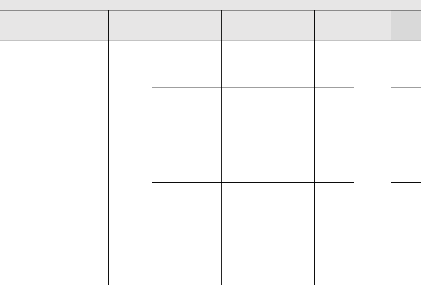
APPROVED FOR PUBLIC RELEASE
113
Top Level Failure Modes
Failure
Mode ID
Failure Mode
Description
Discussion/
Example of Failure
Mode
Tailoring
Recommendation
Common
Defect
Enumeration
Description
Detectability Level
Skill /
Effort required by
SFMEA analysts
Applicability
Reference
TL-DD-7
High level
mismatches of
type (i.e. string,
integer, float)
among software
LRUs
High level means
data across
software LRUs has
the wrong type. If
there is a
mismatch of data
types the result
can be
unpredictable.
During LRU testing
the fault might not
be visible. Once
the LRUS with
different data
types are
integrated this
could cause a
serious interface
fault.
All data interfaces
TL-DD-7-S-1
There is no
overarching
interface spec
to define the
data types for
critical
interfaces
5 - This is often difficult to detect until the data
overflows or underflows
Low - The
specifications
either discuss this
or they don't
All mission
critical systems
Neufelder
2021
Section 3.1
TL-DD-7-C-1
There is an
overarching
specification but
one or more
contractor/LRU
ignored the
specification
2-Failure mode will be detected via testing of a
written requirement
Medium - the
FMEA analyst
needs to read the
test procedures to
ensure this was
tested
Neufelder
2021
Section 3.1
TL-DD-8
The software fails
to detect data that
is corrupt
Corrupt data isn't
considered at all
by the software .
(i.e. this can be
confirmed by
searching through
all specifications
for the word
"corrupt")
All data interfaces
TL-DD-8-S-1
There is no
specification
that requires
consideration of
corrupt data
5 - This requires corruption of data to detect
Low - The
specifications
either discuss this
or they don't
All mission
critical systems
Neufelder
2021
Section 3.1
TL-DD-8-C-1
There is an
overarching
specification but
one or more
contractor/LRU
ignored the
specification
2-Failure mode will be detected via testing of a
written requirement
Medium - the
FMEA analyst
needs to read the
test procedures to
ensure this was
tested
Neufelder
2021
Section 3.1.
Kaner/Faulk/
Nguyen
page 369
Inadequate
protection
against
corrupted
data

APPROVED FOR PUBLIC RELEASE
114
Top Level Failure Modes
Failure
Mode ID
Failure Mode
Description
Discussion/
Example of Failure
Mode
Tailoring
Recommendation
Common
Defect
Enumeration
Description
Detectability Level
Skill /
Effort required by
SFMEA analysts
Applicability
Reference
TL-DD-9
The software fails
to detect missing
data
Missing data isn't
considered at all
by the software
All data interfaces
TL-DD-9-S-1
There is no
specification
that requires
consideration of
missing or null
data
5 - This requires corruption of data to detect
Low - The
specifications
either discuss this
or they don't
All mission
critical systems
Neufelder
2021
Section 3.1
TL-DD-9-C-1
There is an
overarching
specification but
one or more
contractor/LRU
ignored the
specification
2-Failure mode will be detected via testing of a
written requirement
Medium - the
FMEA analyst
needs to read the
test procedures to
ensure this was
tested
Neufelder
2021
Section 3.1
TL-DD-10
The software fails
to detect shifted
data
Shifted data is
when a data table
is inadvertently
modified to be
offset. Usually this
is an offset by 1.
This is caused by
problems with
write operations
that are interrupted
while writing.
Any data interface
that is arranged in a
fixed order
TL-DD-10-S-1
There is no
specification
that requires
consideration of
checking for
shifted data
5 - This requires corruption of data to detect
Low - The
specifications
either discuss this
or they don't
All software with
data tables or
databases. Note
that statistically
these faults don't
happen often but
when they do
happen they can
have serious
consequences.
Neufelder
2021
Section 3.1
TL-DD-10-C-1
There is an
overarching
specification but
one or more
contractor/LRU
ignored the
specification
2-Failure mode will be detected via testing of a
written requirement
Medium - the
FMEA analyst
needs to read the
test procedures to
ensure this was
tested
Neufelder
2021
Section 3.1,
,
Kaner/Faulk/
Nguyen
page 370
Problems in
table drive
programs

APPROVED FOR PUBLIC RELEASE
115
Top Level Failure Modes
Failure
Mode ID
Failure Mode
Description
Discussion/
Example of Failure
Mode
Tailoring
Recommendation
Common
Defect
Enumeration
Description
Detectability Level
Skill /
Effort required by
SFMEA analysts
Applicability
Reference
SL-SE-1
The top level
sequence
identifies the
steps in an
operation but fails
to identify if order
is relevant
Quite often top
level sequence
diagrams or flow
diagrams neglect
to point out if the
order listed is
mandatory.
Any software but
particularly the
software functions
that must conduct
an operation in a
specific order
SL-SE-1-S-1
The
specification is
missing
information on
whether the
functions have
a specific order
5 - If the specifications are themselves faulty it
won't be identified in testing
Medium - It may
require some
knowledge of
system to identify
the sequences
All mission
critical systems
Neufelder
2021
Section 3.1
SL-SE-1-C-1
The
specification
does describe
order
requirements
but the code
doesn't meet
the spec
2-Failure mode will be detected via testing of a
written requirement
Medium - the
FMEA analyst
needs to read the
test procedures to
ensure this was
tested
SL-SE-2
The top level
sequence lists
steps but has the
order incorrect
The top level
diagrams may
show the order
incorrectly
Any software but
particularly the
software functions
that must conduct
an operation in a
specific order
SL-SE-2-S-1
The
specification is
missing
information on
whether the
functions have
a specific order
5 - If the specifications are themselves faulty it
won't be identified in testing
Medium - It may
require some
knowledge of
system to identify
the sequences
All mission
critical systems
Neufelder
2021
Section 3.1
SL-SE-2-C-1
The
specification
does describe
order
requirements
but the code
doesn't meet
the spec
2-Failure mode will be detected via testing of a
written requirement
Medium - the
FMEA analyst
needs to read the
test procedures to
ensure this was
tested

APPROVED FOR PUBLIC RELEASE
116
Top Level Failure Modes
Failure
Mode ID
Failure Mode
Description
Discussion/
Example of Failure
Mode
Tailoring
Recommendation
Common
Defect
Enumeration
Description
Detectability Level
Skill /
Effort required by
SFMEA analysts
Applicability
Reference
TL-A- 1
(continued
next page)
Software is
unable to handle
crossing over
international date
line from east to
west (i.e. reboots
or fails to operate
when time goes
backwards)
Navigational faults
occur when a real
time clock is used
AND time goes to
a previous day
abruptly. Software
engineers often
blindly write code
for error handling
without
considering that
there is a
legitimate case in
which the date can
go backwards.
This can apply to
any system that is
physically capable
of crossing over
the IDL. The IDL
is entirely in water.
Not all vehicles are
able to cross the
IDL.
Any software
system with a real
time clock that is
capable of traveling
over the
international date
line or can travel
inside a system
traveling over the
IDL.
TL-A-1-S-1
There is no
specification for
what the
software should
do when time
goes
backwards
when crossing
the IDL.
4 - If there is no requirement this won't be
tested
This is a well
established failure
mode for aircraft
and naval craft.
However,
software
engineers
designing smaller
weapons such as
missiles might not
consider it. This
failure mode
should only be
considered if the
weapon is
capable of
transitioning over
the IDL.
Aircraft, naval
craft, space
craft, any
airborne
weapon, any
system residing
on any aircraft,
naval craft,
space craft. Any
system with
navigational
software.
Neufelder
2021
Section 3.1
TL-A-1-S-2
The
specification for
what the
software should
do in this
situation is not
appropriate. Ex:
Rebooting is
not an
acceptable
response for
the flight control
system when
the aircraft is
crossing the
IDL.
4 - If there is no requirement this won't be
tested
Low - The
specifications
either discuss this
or they don't
Neufelder
2021
Section 3.1

APPROVED FOR PUBLIC RELEASE
117
Top Level Failure Modes
Failure
Mode ID
Failure Mode
Description
Discussion/
Example of Failure
Mode
Tailoring
Recommendation
Common
Defect
Enumeration
Description
Detectability Level
Skill /
Effort required by
SFMEA analysts
Applicability
Reference
TL-A-1
(cont.)
TL-A-1-C-1
There is a
specification for
what the
software shall
do in this case
but the code
isn't
implemented to
the spec
2-Failure mode will be detected via testing of a
written requirement
Medium - the
FMEA analyst
needs to read the
test procedures to
ensure this was
tested
Neufelder
2021
Section 3.1
TL-A- 2
Software is
unable to handle
crossing over
international date
line from west to
east (i.e. reboots
or fails to operate
when time goes
forward)
Navigational faults
occur when a real
time clock is used
AND time goes
forward abruptly.
This can apply to
any system that is
physically capable
of crossing over
the IDL. The IDL
is entirely in water.
Not all vehicles are
able to cross the
IDL. This fault is
not as likely as the
A-1 fault because
transitioning
forward to the next
day is something
that is typically
considered by
software engineers
(i.e. flying or
driving past
midnight). It's the
transition to an
earlier day that is
often overlooked.
Any software
system with a real
time clock that is
capable of traveling
over the
international date
line or can travel
inside a system
traveling over the
IDL.
TL-A-2-S-1
There is no
specification for
what the
software should
do when time
goes forwards
when crossing
the IDL.
4 - If there is no requirement this won't be
tested
Low - The
specifications
either discuss this
or they don't
Aircraft, naval
craft, space
craft, any
airborne
weapon, any
system residing
on any aircraft,
naval craft,
space craft. Any
system with
navigational
software.
Neufelder
2021
Section 3.1
TL-A-2-S-2
The
specification for
what the
software should
do in this
situation is not
appropriate. Ex:
Rebooting is
not an
acceptable
response for
the flight control
system when
the aircraft is
crossing the
IDL.
5 - If the specifications are themselves faulty it
won't be identified in testing
Low - The
specifications
either discuss this
or they don't
Neufelder
2021
Section 3.1
TL-A-2-C-1
There is a
specification for
what the
software shall
do in this case
but the code
isn't
implemented to
the spec
2-Failure mode will be detected via testing of a
written requirement
Medium - the
FMEA analyst
needs to read the
test procedures to
ensure this was
tested
Neufelder
2021
Section 3.1

APPROVED FOR PUBLIC RELEASE
118
Top Level Failure Modes
Failure
Mode ID
Failure Mode
Description
Discussion/
Example of Failure
Mode
Tailoring
Recommendation
Common
Defect
Enumeration
Description
Detectability Level
Skill /
Effort required by
SFMEA analysts
Applicability
Reference
TL-A- 3
Software is
unable to handle
crossing over
equator from
south to north
This can cause
navigational
problems if the
software isn't
expecting a
sudden change in
the hemisphere.
Any software
system with
guidance/navigation
that is capable of
traveling over the
equator or can
travel inside a
system traveling
over the equator.
TL-A-3-S-1
There is no
specification for
what the
software should
do when
changing
hemispheres
from south to
north.
4 - If there is no requirement this won't be
tested
Low - The
specifications
either discuss this
or they don't
Aircraft, naval
craft, space
craft, any
airborne
weapon, any
system residing
on any aircraft,
naval craft,
space craft. Any
system with
navigational
software.
Neufelder
2021
Section 3.1
TL-A-3-S-2
The
specification for
what the
software should
do in this
situation is not
appropriate. Ex:
Rebooting is
not an
acceptable
response for
the flight control
system when
the aircraft is
crossing the
equator.
5 - If the specifications are themselves faulty it
won't be identified in testing
Low - The
specifications
either discuss this
or they don't
Neufelder
2021
Section 3.1
TL-A-3-C-1
There is a
specification for
what the
software shall
do in this case
but the code
isn't
implemented to
the spec
2-Failure mode will be detected via testing of a
written requirement
Medium - the
FMEA analyst
needs to read the
test procedures to
ensure this was
tested
Neufelder
2021
Section 3.1
TL-A- 4
(continued
next page)
Software is
unable to handle
crossing over
equator from
north to south
This can cause
navigational
problems if the
software isn't
expecting a
sudden change in
the hemisphere.
Any software
system with
guidance/navigation
that is capable of
traveling over the
equator or can
travel inside a
system traveling
over the equator.
TL-A-4-S-1
There is no
specification for
what the
software should
do when
changing
hemispheres
from north to
south
4 - If there is no requirement this won't be
tested
Low - The
specifications
either discuss this
or they don't
Aircraft, naval
craft, space
craft, any
airborne
weapon, any
system residing
on any aircraft,
naval craft,
space craft. Any
system with
Neufelder
2021
Section 3.1

APPROVED FOR PUBLIC RELEASE
119
Top Level Failure Modes
Failure
Mode ID
Failure Mode
Description
Discussion/
Example of Failure
Mode
Tailoring
Recommendation
Common
Defect
Enumeration
Description
Detectability Level
Skill /
Effort required by
SFMEA analysts
Applicability
Reference
TL-A- 4
(cont.)
TL-A-4-S-2
The
specification for
what the
software should
do in this
situation is not
appropriate. Ex:
Rebooting is
not an
acceptable
response for
the flight control
system when
the aircraft is
crossing the
equator.
5 - If the specifications are themselves faulty it
won't be identified in testing
Low - The
specifications
either discuss this
or they don't
navigational
software.
Neufelder
2021
Section 3.1
TL-A-4-C-1
There is a
specification for
what the
software shall
do in this case
but the code
isn't
implemented to
the spec
2-Failure mode will be detected via testing of a
written requirement
Medium - the
FMEA analyst
needs to read the
test procedures to
ensure this was
tested
Neufelder
2021
Section 3.1
TL-A- 5
(continued
on next
page)
Software is
unable to handle
crossing over
north pole
This can cause
navigational
problems if the
software isn't
expecting a
sudden change in
the hemisphere or
extreme longitude
Any software
system with
guidance/navigation
that is capable of
traveling over the
northpole or can
travel inside a
system traveling
TL-A-5-S-1
There is no
specification for
what the
software should
do when near
or over the
north pole
4 - If there is no requirement this won't be
tested
Low - The
specifications
either discuss this
or they don't
Aircraft, naval
craft, space
craft, any
airborne
weapon, any
system residing
on any aircraft,
naval craft,
Neufelder
2021
Section 3.1

APPROVED FOR PUBLIC RELEASE
120
Top Level Failure Modes
Failure
Mode ID
Failure Mode
Description
Discussion/
Example of Failure
Mode
Tailoring
Recommendation
Common
Defect
Enumeration
Description
Detectability Level
Skill /
Effort required by
SFMEA analysts
Applicability
Reference
TL-A- 5
(cont.)
coordinates.
Software
engineers also
often assume
(incorrectly) that
vehicles cannot or
won't go over the
poles.
over the northpole.
TL-A-5-S-2
The
specification for
what the
software should
do in this
situation is not
appropriate. Ex:
Rebooting is
not an
acceptable
response for
the flight control
system when
the aircraft is
crossing the
north pole.
5 - If the specifications are themselves faulty it
won't be identified in testing
Low - The
specifications
either discuss this
or they don't
space craft. Any
system with
navigational
software.
Neufelder
2021
Section 3.1
TL-A-5-C-1
There is a
specification for
what the
software shall
do in this case
but the code
isn't
implemented to
the spec
2-Failure mode will be detected via testing of a
written requirement
Medium - the
FMEA analyst
needs to read the
test procedures to
ensure this was
tested
Neufelder
2021
Section 3.1
TL-A-6
(continued
on next
page)
Software is
unable to handle
crossing over
south pole
This can cause
navigational
problems if the
software isn't
expecting a
sudden change in
the hemisphere or
extreme longitude
Any software
system with
guidance/navigation
that is capable of
traveling over the
southpole or can
travel inside a
system traveling
TL-A-6-S-1
There is no
specification for
what the
software should
do when near
or over the
south pole
4 - If there is no requirement this won't be
tested
Low - The
specifications
either discuss this
or they don't
Aircraft, naval
craft, space
craft, any
airborne
weapon, any
system residing
on any aircraft,
naval craft,
Neufelder
2021
Section 3.1

APPROVED FOR PUBLIC RELEASE
121
Top Level Failure Modes
Failure
Mode ID
Failure Mode
Description
Discussion/
Example of Failure
Mode
Tailoring
Recommendation
Common
Defect
Enumeration
Description
Detectability Level
Skill /
Effort required by
SFMEA analysts
Applicability
Reference
TL-A-6
(cont.)
coordinates.
Software
engineers also
often assume
(incorrectly) that
vehicles cannot or
won't go over the
poles.
over the southpole.
TL-A-6-S-2
The
specification for
what the
software should
do in this
situation is not
appropriate. Ex:
Rebooting is
not an
acceptable
response for
the flight control
system when
the aircraft is
crossing the
south pole.
5 - If the specifications are themselves faulty it
won't be identified in testing
Low - The
specifications
either discuss this
or they don't
space craft. Any
system with
navigational
software.
Neufelder
2021
Section 3.1
TL-A-6-C-1
There is a
specification for
what the
software shall
do in this case
but the code
isn't
implemented to
the spec
2 - Failure mode will be detected via testing of a
written requirement
Medium – The
FMEA analyst
needs to read the
test procedures to
ensure this was
tested
Neufelder
2021
Section 3.1
TL-A-7
(continued
on next
page)
Software is
unable to handle
crossing over any
international line
with 2 different
units of measure.
This can cause
problems with
sensors and
refueling.
Example: ML
software reads
speed limits in
English after
crossing from US
to Canada and
adjusts the speed
incorrectly.
Example 2: An
aircraft designed in
US stops for gas in
Any software
system that is
capable of traveling
over an
international date
line between two
countries that have
conflicting units of
measure.
TL-A-7-S-1
There is no
specification for
what the
software should
do when a
vehicle crosses
over an
international
border between
countries with
different units of
measure
4 - If there is no requirement this won't be
tested
Low - The
specifications
either discuss this
or they don't
Aircraft, naval
craft, space
craft, any
airborne
weapon, any
system residing
on any aircraft,
naval craft,
space craft.
Neufelder
2021
Section 3.1

APPROVED FOR PUBLIC RELEASE
122
Top Level Failure Modes
Failure
Mode ID
Failure Mode
Description
Discussion/
Example of Failure
Mode
Tailoring
Recommendation
Common
Defect
Enumeration
Description
Detectability Level
Skill /
Effort required by
SFMEA analysts
Applicability
Reference
TL-A-7
(cont.)
Canada and gets
20 liters of gas
instead of 20
gallons of gas.
TL-A-7-S-2
The
specification for
what the
software should
do in this
situation is not
appropriate. Ex:
Rebooting is
not an
acceptable
response when
the vehicle is
crossing into a
different
country.
5 - If the specifications are themselves faulty it
won't be identified in testing
Low - The
specifications
either discuss this
or they don't
Neufelder
2021
Section 3.1
TL-A-7-C-1
There is a
specification for
what the
software shall
do in this case
but the code
isn't
implemented to
the spec
2-Failure mode will be detected via testing of a
written requirement
Medium - the
FMEA analyst
needs to read the
test procedures to
ensure this was
tested
Neufelder
2021
Section 3.1
TL-A-8
Algorithm fails to
converge
This can happen
with regression
models
Any software. This
is particularly
relevant for any
software with
algorithms that
performing
approximations.
TL-A-8-S-1
There is no
specification to
ensure that an
algorithm
converges
5 - If the specifications are themselves faulty it
won't be identified in testing
High - This
requires analysis
by algorithm
designers
Mission critical
systems with
algorithms that
perform
regressions and
other
approximations
such as
derivatives
Neufelder
2021
Section 3.1
TL-A-8-C-1
There is a
specification for
what the
software shall
do in this case
but the code
isn't
implemented to
the spec
2-Failure mode will be detected via testing of a
written requirement
Medium - the
FMEA analyst
needs to read the
test procedures to
ensure this was
tested

APPROVED FOR PUBLIC RELEASE
123
Top Level Failure Modes
Failure
Mode ID
Failure Mode
Description
Discussion/
Example of Failure
Mode
Tailoring
Recommendation
Common
Defect
Enumeration
Description
Detectability Level
Skill /
Effort required by
SFMEA analysts
Applicability
Reference
TL-A-9
Sample rate is
insufficient
Signal frequencies
can overlap if the
sampling rate is
too low
Any software. This
is particularly
relevant for any
software with
algorithms that
performing
approximations.
TL-A-9-S-1
There is no
specification to
ensure a
sampling rate
5 - If the specifications are themselves faulty it
won't be identified in testing
High - This failure
mode requires
analysis by
algorithm
designers
Any software
that does signal
analysis
TL-A-9-C-1
There is a
specification for
what the
software shall
do in this case
but the code
isn't
implemented to
the spec
2 - Failure mode will be detected via testing of a
written requirement
Medium - The
FMEA analyst
needs to read the
test procedures to
ensure this was
tested
TL-ML-1
(continued
on next
page)
Population
sampling errors
Population
sampling errors
are when the data
is not
representative of
the population
Any software with
machine learning
TL-ML-1-S-1
Too many
samples from
one subtype.
5 - This won't be detected in testing
Medium - The
FMEA analyst will
need to discuss
with the
engineering team
Machine
learning
software
applications
Neufelder
2021
Section 3.1
TL-ML-1-S-2
Generalization -
Gaps in range
of samples.
5 - This won't be detected in testing
Medium - The
FMEA analyst will
need to discuss
with the
engineering team
Neufelder
2021
Section 3.1
TL-ML-1-S-3
Too few
samples in DB.
5 - This won't be detected in testing
Medium – The
FMEA analyst will
need to discuss
with the
engineering team
Neufelder
2021
Section 3.1

APPROVED FOR PUBLIC RELEASE
124
Top Level Failure Modes
Failure
Mode ID
Failure Mode
Description
Discussion/
Example of Failure
Mode
Tailoring
Recommendation
Common
Defect
Enumeration
Description
Detectability Level
Skill /
Effort required by
SFMEA analysts
Applicability
Reference
TL-ML-1
(cont.)
TL-ML-1-S-4
Sampled data is
outdated.
5- This won't be detected in testing
Medium - the
FMEA analyst will
need to discuss
with the
engineering team
Neufelder
2021
Section 3.1
TL-ML-1-S-5
Seasonal or
location
samples
(multiple NN)
5- This won't be detected in testing
Medium - the
FMEA analyst will
need to discuss
with the
engineering team
Neufelder
2021
Section 3.1
TL-ML-2
Process errors
Process errors are
when the data isn't
collected properly
Any software with
machine learning
TL-ML-2-L-1
Incorrect
labeling of
image.
5- This won't be detected in testing
High - This failure
mode requires
work to uncover
even for the
design engineers
Machine
learning
software
applications
Neufelder
2021
Section 3.1
TL-ML-2-L-2
Factors
selected aren’t
representative.
5- This won't be detected in testing
Medium - the
FMEA analyst will
need to discuss
with the
engineering team
Neufelder
2021
Section 3.1
TL-ML-2-L-3
Factors
selected aren’t
complete.
5- This won't be detected in testing
Medium - the
FMEA analyst will
need to discuss
with the
engineering team
Neufelder
2021
Section 3.1
TL-ML-2-L-4
Incorrect
instrumentation
or resolution,
focal lengths,
LIDARs, etc.
5- This won't be detected in testing
Medium - the
FMEA analyst will
need to discuss
with the
engineering team
Neufelder
2021
Section 3.1

APPROVED FOR PUBLIC RELEASE
125
Top Level Failure Modes
Failure
Mode ID
Failure Mode
Description
Discussion/
Example of Failure
Mode
Tailoring
Recommendation
Common
Defect
Enumeration
Description
Detectability Level
Skill /
Effort required by
SFMEA analysts
Applicability
Reference
TL-ML-3
(continued
next page)
Modeling errors
Modeling errors
are when the
model used for the
ML isn't adequate
Any software with
machine learning
TL-ML-3-M-1
Factors
selected for
model aren’t
representative.
5- This won't be detected in testing
High - This failure
mode requires
work to uncover
even for the
design engineers
Machine
learning
software
applications
Neufelder
2021
Section 3.1
TL-ML-3-M-2
Factors
selected for
model aren’t
complete.
5- This won't be detected in testing
High - This failure
mode requires
work to uncover
even for the
design engineers
Neufelder
2021
Section 3.1
TL-ML-3-M-3
Having more
factors than
data sets
5- This won't be detected in testing
Medium - the
FMEA analyst will
need to discuss
with the
engineering team
Neufelder
2021
Section 3.1
TL-ML-3-M-4
Overfitting the
data
5- This won't be detected in testing
Medium - the
FMEA analyst will
need to discuss
with the
engineering team
Neufelder
2021
Section 3.1
TL-ML-3-M-5
Inadequate
model - not
enough layers
5- This won't be detected in testing
High - This failure
mode requires
work to uncover
even for the
design engineers
Neufelder
2021
Section 3.1
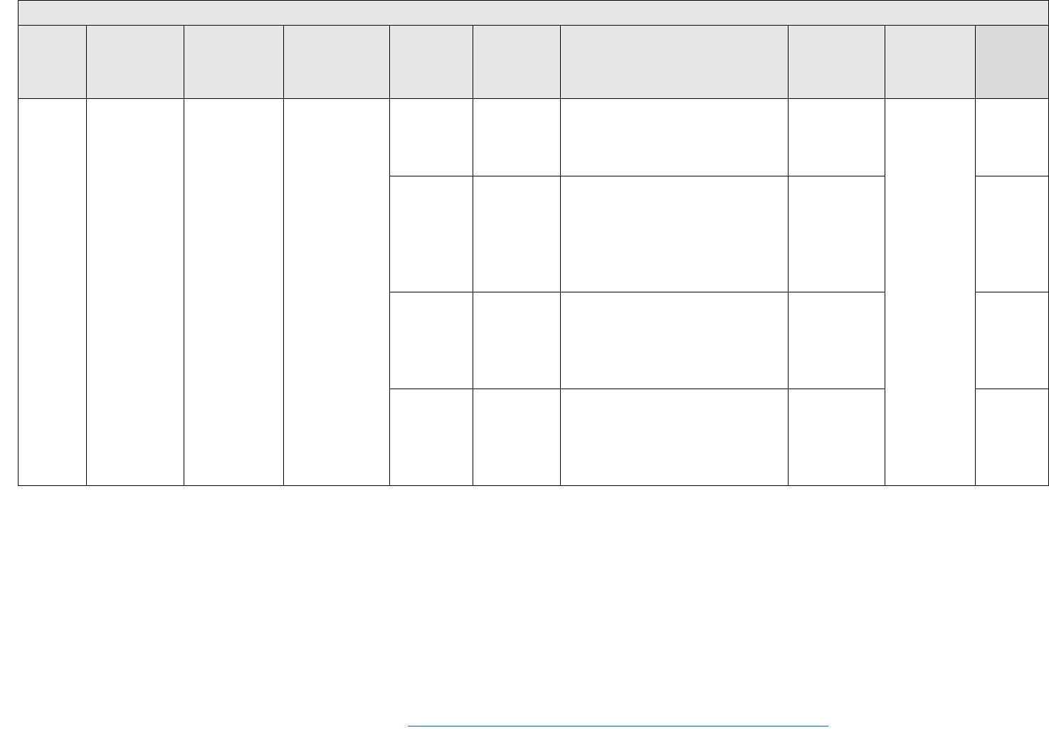
APPROVED FOR PUBLIC RELEASE
126
Top Level Failure Modes
Failure
Mode ID
Failure Mode
Description
Discussion/
Example of Failure
Mode
Tailoring
Recommendation
Common
Defect
Enumeration
Description
Detectability Level
Skill /
Effort required by
SFMEA analysts
Applicability
Reference
TL-ML-3
(cont.)
TL-ML-3-M-6
Not enough
computing
power
2- Detectable with requirements testing
Low - either there
is or there isn't
enough
computing power
Neufelder
2021
Section 3.1
TL-ML-3-M-7
Using more
than one NN
and output
fusion
5- This won't be detected in testing
High - This failure
mode requires
work to uncover
even for the
design engineers
Neufelder
2021
Section 3.1
TL-ML-3-M-8
Incorrect
calibrated
confidence
5- This won't be detected in testing
Medium - the
FMEA analyst will
need to discuss
with the
engineering team
Neufelder
2021
Section 3.1
TL-ML-3-M-9
Mismatch
between
validation data
and actual
validation
5- This won't be detected in testing
Medium - the
FMEA analyst will
need to discuss
with the
engineering team
Neufelder
2021
Section 3.1
46
Microsoft 2022 Failure mode analysis for Azure applications,10/13/2022,https://docs.microsoft.com/en-us/azure/architecture/resiliency/failure-mode-analysis

APPROVED FOR PUBLIC RELEASE
127
Capability Level Failure Modes
Failure
Mode ID
Failure Mode
Description
Discussion /
Example of failure
mode
Applicability
Common
Defect
Enumeration
Description
Detectability Level
Skill / Effort
Required by
SFMEA analysts
Applicability
Reference
TL- SM-1 through TL-SM-12 failure modes apply to any feature that has it's own state machine
TL- EH-1 through TL-EH-30 failure modes apply to specific capabilities.
CL-EH-1
Write errors to
data base or
cache or data
storage not
detected
Anytime there is a
write operation to
a data element it
may not be
successful.
Any system with a
database or file input
output
CL-EH-1-S-1
The are no
specifications
to require that
write operation
success be
returned
5 - Without a requirement, this failure mode
won't be explicitly tested.
Low - The
specifications
either discuss this
or they don't
Any
capability
interfacing
with a
database,
data storage
NEUF 2014,
Table 3.3.2.1.3-
1,
Microsoft 2022
46
CL-EH-1-C-1
There is an
explicit
specification
but the code
doesn't comply
2 - Failure mode will be detected via testing of a
written requirement
Medium - The
FMEA analyst
needs to read the
test procedures to
ensure this was
tested
CL-EH-2
(continued
next page)
Write errors to
data base or
cache or data
storage not
properly handled
The software
must not only
detect failed write
operations but do
the correct thing
when the
operation fails.
Ex: Rebooting or
ignoring the write
fault is rarely the
correct thing.
Any system with a
database or file input
output
CL-EH-2-S-1
The are no
specifications
to require that
specific
handling of
failed write
operations
5 - Without a requirement, this failure mode
won't be explicitly tested
Low - The
specifications
either discuss this
or they don't
Any
capability
interfacing
with a
database,
data storage
NEUF 2014,
Table 3.3.2.1.3-
1, Microsoft 2022

APPROVED FOR PUBLIC RELEASE
128
Capability Level Failure Modes
Failure
Mode ID
Failure Mode
Description
Discussion /
Example of failure
mode
Applicability
Common
Defect
Enumeration
Description
Detectability Level
Skill / Effort
Required by
SFMEA analysts
Applicability
Reference
CL-EH-2
(cont.)
CL-EH-2-C-1
There is an
explicit
specification
but the code
doesn't comply
2 - Failure mode will be detected via testing of a
written requirement
Medium - The
FMEA analyst
needs to read the
test procedures to
ensure this was
tested
CL-EH-3
Read errors to
database or
cache or data
storage not
detected
Anytime there is a
read operation to
a data element it
may not be
successful.
Any system with a
database or file input
output
CL-EH-3-S-1
The are no
specifications
to require that
read operation
success be
returned
5 - Without a requirement, the software tester
won't assess whether there is an advisement
Low - The
specifications
either discuss this
or they don't
Any
capability
interfacing
with a
database,
data storage
NEUF 2014,
Table 3.3.2.1.3-
1, Microsoft 2022
CL-EH-3-C-1
There is an
explicit
specification
but the code
doesn't comply
2 - Failure mode will be detected via testing of a
written requirement
Medium - The
FMEA analyst
needs to read the
test procedures to
ensure this was
tested

APPROVED FOR PUBLIC RELEASE
129
Capability Level Failure Modes
Failure
Mode ID
Failure Mode
Description
Discussion /
Example of failure
mode
Applicability
Common
Defect
Enumeration
Description
Detectability Level
Skill / Effort
Required by
SFMEA analysts
Applicability
Reference
CL-EH-4
Read errors to
database or
cache or data
storage not
properly handled
The software
must not only
detect failed read
operations but do
the correct thing
when the
operation fails.
Ex: Rebooting or
ignoring the read
fault is rarely the
correct thing.
Any system with a
database or file input
output
CL-EH-4-S-1
The are no
specifications
to require that
specific
handling of
failed read
operations
5 - Without a requirement, this failure mode
won't be explicitly tested
Low - The
specifications
either discuss this
or they don't
Any
capability
interfacing
with a
database,
data storage
NEUF 2014,
Table 3.3.2.1.3-
1, Microsoft 2022
CL-EH-4-C-1
There is an
explicit
specification
but the code
doesn't comply
2 -Failure mode will be detected via testing of a
written requirement
Medium - The
FMEA analyst
needs to read the
test procedures to
ensure this was
tested
CL-EH-5
Software fails to
detect a failed
SQL connection
SQL connections
can fail if the
connection string
isn't correct
Any system with a
database
CL-EH-5-S-1
There are no
specifications
to require that
SQL
connection
failures be
returned by the
software
5 - Without a requirement, this failure mode
won't be explicitly tested
Low - The
specifications
either discuss this
or they don't
Any
capability
that is
connecting to
a database
Microsoft 2022
CL-EH-5-C-1
There is an
explicit
specification
but the code
doesn't comply
2 - Failure mode will be detected via testing of a
written requirement
Medium - The
FMEA analyst
needs to read the
test procedures to
ensure this was
tested

APPROVED FOR PUBLIC RELEASE
130
Capability Level Failure Modes
Failure
Mode ID
Failure Mode
Description
Discussion /
Example of failure
mode
Applicability
Common
Defect
Enumeration
Description
Detectability Level
Skill / Effort
Required by
SFMEA analysts
Applicability
Reference
CL-EH-6
Software fails to
properly recover
from a failed SQL
connection
When the SQL
connection fails
the software
needs to do the
correct thing.
Rebooting or
ignoring the fault
is rarely the
correct thing.
Any system with a
database
CL-EH-6-S-1
There are no
specifications
to require that
SQL
connection
failures be
properly
handled
5 - Without a requirement, this failure mode
won't be explicitly tested
Low - The
specifications
either discuss this
or they don't
Any
capability
that is
connecting to
a database
Microsoft 2022
CL-EH-6-C-1
There is an
explicit
specification
but the code
doesn't comply
2 - Failure mode will be detected via testing of a
written requirement
Medium - The
FMEA analyst
needs to read the
test procedures to
ensure this was
tested
CL-EH-7
Software fails to
detect or handle a
database
connection limit
There can/will be
limits on the
maximum number
of concurrent
database
connections. The
software needs to
be designed for
this.
Any system with a
database
CL-EH-7-S-1
There are no
specifications
to require that
the software
detect when
the maximum
database
connection limit
has been
reached
5 - Without a requirement, this failure mode
won't be explicitly tested
Low - The
specifications
either discuss this
or they don't
Any
capability
that is
connecting to
a database
Microsoft 2022
CL-EH-7-C-1
There is an
explicit
specification
but the code
doesn't comply
2-Failure mode will be detected via testing of a
written requirement
Medium - the
FMEA analyst
needs to read the
test procedures to
ensure this was
tested

APPROVED FOR PUBLIC RELEASE
131
Capability Level Failure Modes
Failure
Mode ID
Failure Mode
Description
Discussion /
Example of failure
mode
Applicability
Common
Defect
Enumeration
Description
Detectability Level
Skill / Effort
Required by
SFMEA analysts
Applicability
Reference
CL-EH-8
Software fails to
detect or handle a
database
connection limit
There can/will be
limits on the
maximum number
of concurrent
database
connections. The
software needs to
be not only detect
this but handle
the event
properly.
Any system with a
database
CL-EH-8-S-1
There are no
specifications
to require that
the software
properly handle
when the
maximum
database
connection limit
has been
reached
5 - Without a requirement, this failure mode
won't be explicitly tested
Low - The
specifications
either discuss this
or they don't
Any
capability
that is
connecting to
a database
Microsoft 2022
CL-EH-8-C-1
There is an
explicit
specification
but the code
doesn't comply
2 - Failure mode will be detected via testing of a
written requirement
Medium - The
FMEA analyst
needs to read the
test procedures to
ensure this was
tested
CL-EH-9
(continued
next page)
Software fails to
detect that a
request to a
service has failed
The software
might request a
service that is
unavailable
Any real time
software
CL-EH-9-S-1
There are no
specifications
to require that
the software
detect a failed
service request
5 - Without a requirement, this failure mode
won't be explicitly tested
Low - The
specifications
either discuss this
or they don't
Any
capability
making a
service
request
Microsoft 2022

APPROVED FOR PUBLIC RELEASE
132
Capability Level Failure Modes
Failure
Mode ID
Failure Mode
Description
Discussion /
Example of failure
mode
Applicability
Common
Defect
Enumeration
Description
Detectability Level
Skill / Effort
Required by
SFMEA analysts
Applicability
Reference
CL-EH-9
(cont.)
CL-EH-9-S-2
There are no
specifications
to require that
the software
detect a failed
call to a remote
service
5 - Without a requirement, this failure mode
won't be explicitly tested
Low - The
specifications
either discuss this
or they don't
CL-EH-9-C-1
There is an
explicit
specification
but the code
doesn't comply
2 - Failure mode will be detected via testing of a
written requirement
Medium - The
FMEA analyst
needs to read the
test procedures to
ensure this was
tested
CL-EH-10
Software fails to
properly recover
from a failed
service request
The software
must do the
correct thing
when a service
request fails
Any real time
software
CL-EH-10-S-1
There are no
specifications
to require that
the software
properly handle
a failed service
request
5 - Without a requirement, this failure mode
won't be explicitly tested
Low - The
specifications
either discuss this
or they don't
Any
capability
making a
service
request
Microsoft 2022
CL-EH-10-C-1
There is an
explicit
specification
but the code
doesn't comply
2 - Failure mode will be detected via testing of a
written requirement
Medium - The
FMEA analyst
needs to read the
test procedures to
ensure this was
tested
TL-FC-1 through TL-FC-7 failure modes apply to specific capabilities

APPROVED FOR PUBLIC RELEASE
133
Capability Level Failure Modes
Failure
Mode ID
Failure Mode
Description
Discussion /
Example of failure
mode
Applicability
Common
Defect
Enumeration
Description
Detectability Level
Skill / Effort
Required by
SFMEA analysts
Applicability
Reference
CL-FC-1
Feature or use
case conflicts with
other use cases
Large complex
systems are
written by multiple
software
engineers and
sometimes
multiple
organizations.
So, it’s possible
that different
capabilities
conflict with each
other.
This is applicable for
any system but
particularly relevant
for large systems
developed by
multiple
organizations
CL-FC-1-S-1
The software
specifications
for this
capability
directly conflict
with the
software
specifications
for other
features
5 - Any fault in the requirements won't be found
in testing
Medium -
Identifying
conflicts can take
time if the system
is relatively
large/complex
Large
systems with
many
capabilities
NEUF2021
section 3.2
CL-FC-1-C-1
The
specifications
for this
capability don’t
conflict with
other
capabilities but
the code was
written to
conflict with
how other
capabilities are
developed
2 - Failure mode will be detected via testing of a
written requirement
Medium - The
FMEA analyst
needs to read the
test procedures to
ensure this was
tested
NEUF2021
section 3.2
CL-FC-2
Feature or use
case is over
engineered or has
unnecessary
functionality
Overengineering
can lead to
unreliable
software because
unnecessary
software features
or unnecessary
complexity in
necessary
features cause
failures that effect
the mission.
This is applicable for
all software systems
CL-FC-2-S-1
The software
specifications
clearly have
unnecessary
complexity or
unnecessary
features
5 - Any fault in the requirements won't be found
in testing
Medium -
Identifying over
engineering
requires
knowledge of the
system.
Any mission
critical
capability
NEUF2021
Section 3.2
CL-FC-2-C-1
The software
specifications
aren't
overengineered
but the code is
overengineered
2 - Failure mode will be detected via testing of a
written requirement
Medium - The
FMEA analyst
needs to read the
test procedures to
ensure this was
tested
BEIZER Bugs in
Perspective
3.2.2,
Kaner/Faulk/Ngu
yen page 365
Excessive
functionality

APPROVED FOR PUBLIC RELEASE
134
Capability Level Failure Modes
Failure
Mode ID
Failure Mode
Description
Discussion /
Example of failure
mode
Applicability
Common
Defect
Enumeration
Description
Detectability Level
Skill / Effort
Required by
SFMEA analysts
Applicability
Reference
TL-PR-3, PR-7 and PR-8 apply at the capability level
CL-PR-1
Capability is
interrupted while
executing
Software
engineers often
fail to consider
what the system
does when one
capability is
interrupted or not
available
This is applicable for
all software systems
CL-PR-1-S-1
The software
specifications
fail state what
happens when
a capability is
interrupted.
4 - Since there is no specification this won't be
identified in testing
Low - either the
specification
discusses what
the software is
required to do
when this
capability is
interrupted or it
doesn’t
Any mission
critical
capability
NEUF2021
section 3.2
CL-PR-1-C-1
The software
specifications
for interruption
of a capability
are clear but
the code
doesn't meet
the spec.
2 - Failure mode will be detected via testing of a
written requirement
Medium - The
FMEA analyst
needs to read the
test procedures to
ensure this was
tested
NEUF2021
section 3.2
CL-T-1
This capability
takes too long to
execute
It's a common
problem for
software
engineering to
overlook that time
it takes for the
capability to
execute. When
there are mission
critical timing
requirements this
can be a critical
failure.
This is applicable for
all software systems
CL-T-1-S-1
Capability is
missing
essential timing
requirements
(missing
budget)
4 - Since there is no specification this won't be
identified in testing
Low - Either the
timing budgets
are specified or
they aren't
Any mission
critical
capability
NEUF2021
section 3.2
CL-T-1-C-1
Capability has
timing
requirements
that aren't met
by the software
2 - Failure mode will be detected via testing of a
written requirement
Medium - The
FMEA analyst
needs to read the
test procedures to
ensure this was
tested
NEUF2021
section 3.2,
Kaner/Faulk/Ngu
yen page 368
slow program

APPROVED FOR PUBLIC RELEASE
135
Capability Level Failure Modes
Failure
Mode ID
Failure Mode
Description
Discussion /
Example of failure
mode
Applicability
Common
Defect
Enumeration
Description
Detectability Level
Skill / Effort
Required by
SFMEA analysts
Applicability
Reference
CL-T-2
Capability
executes in
correct order but
too early
When critical
features execute
too early that can
cause damage to
hardware or loss
of mission
This is applicable for
all software systems
CL-T-2-S-1
Specifications
allow for the
feature to
execute too
early via
commission or
omission
4 - Since there is no specification this won't be
identified in testing
Low - Either the
timing budgets
are specified or
they aren't
Any mission
critical
capability
NEUF2021
section 3.2
CL-T-2-C-1
Capability has
timing
requirements
that aren't met
by the software
2 - Failure mode will be detected via testing of a
written requirement
Medium - The
FMEA analyst
needs to read the
test procedures to
ensure this was
tested
NEUF2021
section 3.2
CL-T-3
Capability
executes in
correct order but
too late
When critical
features execute
too early that can
leaded to faulted
engagements
This is applicable for
all software systems
CL-T-3-S-1
Specifications
allow for the
feature to
execute too
late via
commission or
omission
4 - Since there is no specification this won't be
identified in testing
Low - Either the
timing budgets
are specified or
they aren't
Any mission
critical
capability
NEUF2021
section 3.2
CL-T-3-C-1
Capability has
timing
requirements
that aren't met
by the software
2 - Failure mode will be detected via testing of a
written requirement
Medium - The
FMEA analyst
needs to read the
test procedures to
ensure this was
tested
NEUF2021
section 3.2

APPROVED FOR PUBLIC RELEASE
136
Capability Level Failure Modes
Failure
Mode ID
Failure Mode
Description
Discussion /
Example of failure
mode
Applicability
Common
Defect
Enumeration
Description
Detectability Level
Skill / Effort
Required by
SFMEA analysts
Applicability
Reference
CL-T-4
Capability has a
race condition
Race conditions
are difficult to
detect in testing
and usually quite
severe in effect
This is applicable for
all software systems
CL-T-4-D-1
The design
doesn't require
serialized
access to
shared
resources
4 - Since there is no specification this won't be
identified in testing
High - Identifying
race conditions
from the design
takes some work.
Any mission
critical
capability
NEUF2021
section 3.2
CL-T-4-C-1
The design
requires
serialized
access to
shared
resource but
the code wasn't
written to
design
2-Failure mode will be detected via testing of a
written requirement
Medium - The
FMEA analyst
needs to read the
test procedures to
ensure this was
tested
BEIZER Bugs in
Perspective
3.3.3 (hardware
induced), 3.3.6
Software
resource
induced,
Kaner/Faulk/Ngu
yen page 372
race conditions
CL-T-5
Capability has an
infinite loop
Infinite loops will
cause the
software to hang
and aren't always
easy to spot.
They can occur
when software
engineers
assume that
certain events will
always happen.
Ex: The software
waits until all
batteries are up.
There can be an
infinite loop if the
batteries never
come up.
This is applicable for
all software systems
CL-T-5-D-1
The software
design doesn't
have a finite
and guan teed
criteria for all
loops to
terminate
4 - Since there is no specification this won't be
identified in testing
Medium - The
analyst needs to
understand
software design
enough to know
where to look for
functions that are
looping
Any mission
critical
capability
NEUF2021 3.2
CL-T-5-C-1
The design is
correct but the
code isn't
implemented
as per design
2 - Failure mode will be detected via testing of a
written requirement
Medium - The
FMEA analyst
needs to read the
test procedures to
ensure this was
tested
BEIZER Bugs in
Perspective
3.4.3,
Kaner/Faulk/Ngu
yen page 371
Infinite loops
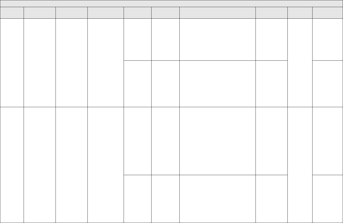
APPROVED FOR PUBLIC RELEASE
137
Capability Level Failure Modes
Failure
Mode ID
Failure Mode
Description
Discussion /
Example of failure
mode
Applicability
Common
Defect
Enumeration
Description
Detectability Level
Skill / Effort
Required by
SFMEA analysts
Applicability
Reference
CL-T-6
Capability is
unable to make
interrupt
scheduling
requirements
When scheduling
requirements for
interrupts aren't
met there are
dropped
commands. This
is difficult to
detect in testing
and usually very
severe in
consequence.
This is applicable for
all multi threaded
software systems
CL-T-6-D-1
The design
doesn't require
interrupt rates
that support
scheduling
4 - Since there is no specification this won't be
identified in testing
Low - either there
are schedulability
requirements or
there aren't
Any mission
critical
capability
NEUF2021 3.2
CL-T-6-C-1
The design
does require
interrupt rates
that support
scheduling but
the code is
written to the
design
2-Failure mode will be detected via testing of a
written requirement
Medium - the
FMEA analyst
needs to read the
test procedures to
ensure this was
tested
NEUF2021 3.2
CL-SE-1
Processing is
parallel when it
should be serial
If processing is
parallel and
should be serial
there could be
some problems
with
synchronization.
This is applicable for
all multi threaded
software systems
CL-SE-1-D-1
The design
doesn't specify
whether
processing
should be
parallel or
serial
4 - Since there is no specification this won't be
identified in testing
Medium - The
analyst needs to
understand how
to read sequence
diagrams and
identify cases that
might have
synchronization
problems
Any mission
critical
capability
NEUF2021 3.2
CL-SE-1-C-1
The design
clearly
specifies that
processing is
parallel but the
code is written
to design
2-Failure mode will be detected via testing of a
written requirement
Medium - the
FMEA analyst
needs to read the
test procedures to
ensure this was
tested
NEUF2021 3.2
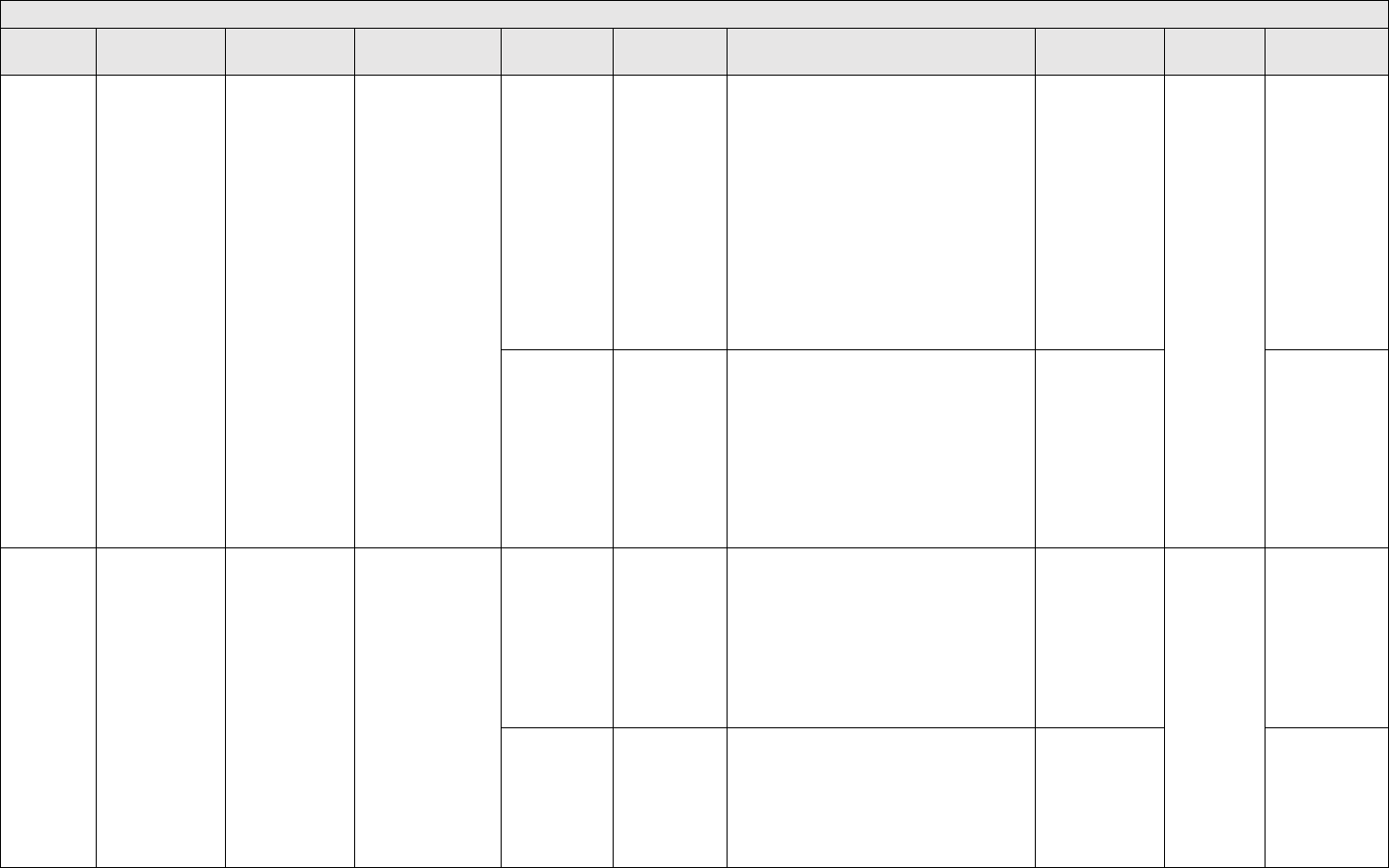
APPROVED FOR PUBLIC RELEASE
138
Capability Level Failure Modes
Failure
Mode ID
Failure Mode
Description
Discussion /
Example of failure
mode
Applicability
Common
Defect
Enumeration
Description
Detectability Level
Skill / Effort
Required by
SFMEA analysts
Applicability
Reference
CL-SE - 2
Processing is
serial when it
should be parallel
If processing is
serial and it
should be parallel
there could be
some problems
with
synchronization.
This is applicable for
all multi threaded
software systems
CL-SE-2-D-1
The design
doesn't specify
whether
processing
should be
parallel or
serial
4 - Since there is no specification this won't be
identified in testing
Medium - The
analyst needs to
understand how
to read sequence
diagrams and
identify cases that
might have
synchronization
problems
Any mission
critical
capability
NEUF2021 3.2
CL-SE-2-C-1
The design
clearly
specifies that
processing is
serial but the
code is written
to design
2 - Failure mode will be detected via testing of a
written requirement
Medium - The
FMEA analyst
needs to read the
test procedures to
ensure this was
tested
NEUF2021 3.2
CL-SE - 3
Processing starts
before all
prerequisites are
satisfied
This is slightly
different than an
task that executes
too early. With
this failure mode,
the task is
executed too
soon with regards
to order not the
time.
This is applicable for
all systems
CL-SE-3-D-1
The design
doesn't show
the
prerequisites to
be satisfied for
a particular
task
4 - Since there is no specification this won't be
identified in testing
Medium - The
analyst needs to
understand how
to read sequence
diagrams
Any mission
critical
capability
NEUF2021 3.2
CL-SE-3-C-1
The design
clearly shows
the
prerequisites to
be satisfied but
the code isn't
implemented to
design
2 -Failure mode will be detected via testing of a
written requirement
Medium - the
FMEA analyst
needs to read the
test procedures to
ensure this was
tested
NEUF2021 3.2,
Kaner/Faulk/Ngu
yen page 372
Assumption that
one event or task
has finished
before another
one is started

APPROVED FOR PUBLIC RELEASE
139
Capability Level Failure Modes
Failure
Mode ID
Failure Mode
Description
Discussion /
Example of failure
mode
Applicability
Common
Defect
Enumeration
Description
Detectability Level
Skill / Effort
Required by
SFMEA analysts
Applicability
Reference
CL-SE - 4
Processing ends
before everything
is cleaned up
This is a common
mistake when the
software logic
proceeds to the
next task without
cleaning up the
current task
This is applicable for
all systems
CL-SE-4-D-1
The design
doesn't show
the cleanup
tasks in the
sequence
diagram
4 - Since there is no specification this won't be
identified in testing
Medium - The
analyst needs to
understand how
to read sequence
diagrams
Any mission
critical
capability
NEUF2021 3.2
CL-SE-4-C-1
The sequence
diagram clearly
shows the
clean up tasks
but the code
isn't
implemented to
the design
2-Failure mode will be detected via testing of a
written requirement
Medium - the
FMEA analyst
needs to read the
test procedures to
ensure this was
tested
NEUF2021 3.2,
BEIZER 7.2.2, ,
Kaner/Faulk/Ngu
yen page 372
Tasks start
before
prerequisites are
met
CL-SE - 5
Processing is
executed in the
wrong order
This is a common
mistake when the
order of the tasks
is simply wrong.
This is applicable for
all systems. It is
most relevant for
software functions
that need to execute
in a specific order.
CL-SE-5-D-1
The design
doesn't show
the order of the
tasks in the
sequence
diagram
4 - Since there is no specification this won't be
identified in testing
Medium - The
analyst needs to
understand how
to read sequence
diagrams and
understand the
system well
enough to know
when something
is out of order
Any mission
critical
capability
NEUF2021 3.2
CL-SE-5-C-1
The sequence
diagram clearly
shows the
order of the
tasks but the
code isn't
implemented to
the design
2-Failure mode will be detected via testing of a
written requirement
Medium - the
FMEA analyst
needs to read the
test procedures to
ensure this was
tested
NEUF2021 3.2

APPROVED FOR PUBLIC RELEASE
140
Capability Level Failure Modes
Failure
Mode ID
Failure Mode
Description
Discussion /
Example of failure
mode
Applicability
Common
Defect
Enumeration
Description
Detectability Level
Skill / Effort
Required by
SFMEA analysts
Applicability
Reference
CL-SE-6
The capability or
some steps in it,
executes too
many times
The capability
itself may be
called from the
executive too
many times or
some steps within
the capability may
execute too many
times. Example:
A dishwasher is
supposed to
rinse, wash, rinse,
dry. But it
executes the
whole cycle twice
or it executes one
of these steps
more than once.
This is applicable for
all systems. It is
most relevant for
software functions
that execute a series
of operations in a
specific order
CL-SE-6-D-1
The design
doesn't show
the order of the
tasks in the
sequence
diagram
4 - Since there is no specification this won't be
identified in testing
Medium - The
analyst needs to
understand how
to read the flow
and sequence
diagrams and
understand the
system well
enough to know
when the
capability or the
steps in it are
executing too
many times
Any mission
critical
capability
NEUF2021 3.2
CL-SE-6-C-1
The sequence
diagram clearly
shows the
order of the
tasks but the
code isn't
implemented to
the design
2-Failure mode will be detected via testing of a
written requirement
Medium - the
FMEA analyst
needs to read the
test procedures to
ensure this was
tested
NEUF2021 3.2

APPROVED FOR PUBLIC RELEASE
141
Capability Level Failure Modes
Failure
Mode ID
Failure Mode
Description
Discussion /
Example of failure
mode
Applicability
Common
Defect
Enumeration
Description
Detectability Level
Skill / Effort
Required by
SFMEA analysts
Applicability
Reference
CL-SE-7
The capability or
some steps in it,
don’t execute at
all
The capability
itself may be not
be called at all
some steps in it
might not be
called. Example:
Crysat 1 software
failed to call the
capability that
turns off the main
engine. Example
2: A dishwasher
is supposed to
rinse, wash, rinse,
dry. But it
neglects to
execute the rinse
before the wash.
This is applicable for
all systems. It is
most relevant for
software functions
that execute a series
of operations in a
specific order
CL-SE-7-D-1
The design
doesn't show
the order of the
tasks in the
sequence
diagram
4 - Since there is no specification this won't be
identified in testing
Medium - The
analyst needs to
understand how
to read the flow
and sequence
diagrams and
understand the
system well
enough to know
when the
capability or the
steps in it aren't
executing
Any mission
critical
capability
NEUF2021 3.2
CL-SE-7-C-1
The sequence
diagram clearly
shows the
order of the
tasks but the
code isn't
implemented to
the design
2-Failure mode will be detected via testing of a
written requirement
Medium - the
FMEA analyst
needs to read the
test procedures to
ensure this was
tested
NEUF2021 3.2
All top level DD-1 to DD-10 failure modes apply to specific capabilities. The focus is on the data definitions within the capabilities as opposed to across different LRUs.
CL-DD-1
Software
assumes data is
available when it
may not be
The software will
behave
unpredictably if it
attempts to
operate on data
that's not
available.
Example, upon
initialization the
state of the
system is not yet
All software systems
CL-DD-1-D-1
There are no
data flow or
sequence
diagrams to
shown when
data is
available/not
available
4 - Since there is no specification this won't be
identified in testing
Medium - This
requires looking
at data and flow
diagrams
Any mission
critical
capability
NEUF2021 3.2

APPROVED FOR PUBLIC RELEASE
142
Capability Level Failure Modes
Failure
Mode ID
Failure Mode
Description
Discussion /
Example of failure
mode
Applicability
Common
Defect
Enumeration
Description
Detectability Level
Skill / Effort
Required by
SFMEA analysts
Applicability
Reference
available. So, the
software shouldn't
proceed with any
commands until
the state is
available.
CL-DD-1-C-1
There are data
flow diagrams
and/or
sequence
diagrams which
clearly identify
the availability
of the data over
time but the
code isn't
written to
design
2-Failure mode will be detected via testing of a
written requirement
Medium - the
FMEA analyst
needs to read the
test procedures to
ensure this was
tested
NEUF2021 3.2
CL-DD-2
Software retains
data when it
should not
The software will
behave
unpredictably if it
attempts to retain
data when it
shouldn't.
Example: If a
driverless vehicle
runs out of gas,
the software
should not
remember that it
was driving at 70
mph when the car
is refueled.
All software systems
CL-DD-2-D-1
There are no
data flow or
other diagrams
to show the
data retention
requirements
4 - Since there is no specification this won't be
identified in testing
Medium - This
requires looking
at data and flow
diagrams
Any mission
critical
capability
NEUF2021 3.2
CL-DD-2-C-1
There are data
flow diagrams
that clearly
shows the
retention of
data but the
code is written
to design
2-Failure mode will be detected via testing of a
written requirement
Medium - the
FMEA analyst
needs to read the
test procedures to
ensure this was
tested
NEUF2021 3.2
CL-DD-3
(continued
next page)
Software fails to
retain data when
it should
The software will
behave
unpredictably if it
attempts to retain
data when it
shouldn't.
Example: If the
system has a
hardware fault
and it is turned
All software systems
CL-DD-3-D-1
There are no
data flow or
other diagrams
to show the
data retention
requirements
4 - Since there is no specification this won't be
identified in testing
Medium - This
requires looking
at data and flow
diagrams
Any mission
critical
capability
NEUF2021 3.2

APPROVED FOR PUBLIC RELEASE
143
Capability Level Failure Modes
Failure
Mode ID
Failure Mode
Description
Discussion /
Example of failure
mode
Applicability
Common
Defect
Enumeration
Description
Detectability Level
Skill / Effort
Required by
SFMEA analysts
Applicability
Reference
CL-DD-3
(cont.)
off, it should
remember upon
start up that it is
still faulted.
CL-DD-3-C-1
There are data
flow diagrams
or data
definitions that
clearly shows
the retention of
data but the
code is written
to design
2 - Failure mode will be detected via testing of a
written requirement
Medium - the
FMEA analyst
needs to read the
test procedures to
ensure this was
tested
CL-DD-4
Software fails to
refresh data when
it should
The software will
behave
unpredictably if it
attempts to use
stale data. Ex: A
temperature
monitor on the
experimental
space chamber
uses old data to
make decisions
and opens when
the chamber is
not safe.
All software systems
CL-DD-4-D-1
There are no
data flow or
other diagrams
to show the
when and how
data is
refreshed
4 - Since there is no specification this won't be
identified in testing
Medium - This
requires looking
at data and flow
diagrams
Any mission
critical
capability
NEUF2021 3.2
CL-DD-4-C-1
There are data
flow diagrams
or data
definitions that
clearly shows
the
refreshment of
data but the
code is written
to design
2 - Failure mode will be detected via testing of a
written requirement
Medium - The
FMEA analyst
needs to read the
test procedures to
ensure this was
tested
NEUF2021 3.2
CL-DD-5
(continued
next page)
Software
refreshes data
more often than it
should
The software may
be sluggish if it
monitors for data
changes too
often.
All software systems
CL-DD-5-D-1
There are no
data flow or
other diagrams
to show the
when and how
data is
refreshed
4 - Since there is no specification this won't be
identified in testing
Medium - This
requires looking
at data and flow
diagrams
Any mission
critical
capability
NEUF2021 3.2

APPROVED FOR PUBLIC RELEASE
144
Capability Level Failure Modes
Failure
Mode ID
Failure Mode
Description
Discussion /
Example of failure
mode
Applicability
Common
Defect
Enumeration
Description
Detectability Level
Skill / Effort
Required by
SFMEA analysts
Applicability
Reference
CL-DD-5
(cont.)
CL-DD-5-C-1
There are data
flow diagrams
or data
definitions that
clearly shows
the
refreshment of
data but the
code is written
to design
2 - Failure mode will be detected via testing of a
written requirement
Medium - The
FMEA analyst
needs to read the
test procedures to
ensure this was
tested
NEUF2021 3.2
TL-U-1 to TL-U-10 failure modes can apply to the user interface for a specific capability
TL-A-1 to TL-A-7 failure modes apply to guidance and navigation capabilities and TL-A-8 through 10 to other algorithms in the capability
CL-A-1
Algorithm doesn't
work for entire
range of inputs
The accuracy of
the algorithm may
diminish based on
the ranges of
inputs.
All software systems
but particularly the
software functions
that are
mathematically
intensive
CL-A-1-D-1
The design
specifications
for the
algorithm are
incorrect
4 - Since there is no specification this won't be
identified in testing
High - This
requires input
from algorithm
designers and
people
knowledgeable of
the system
Any mission
critical
algorithm
NEUF2021 3.2
CL-A-1-C-1
The design
specification is
correct but the
code isn't
written to spec
2 - Failure mode will be detected via testing of a
written requirement
Medium - The
FMEA analyst
needs to read the
test procedures to
ensure this was
tested
Kaner/Faulk/Ngu
yen page 369
calculation errors

APPROVED FOR PUBLIC RELEASE
145
Capability Level Failure Modes
Failure
Mode ID
Failure Mode
Description
Discussion /
Example of failure
mode
Applicability
Common
Defect
Enumeration
Description
Detectability Level
Skill / Effort
Required by
SFMEA analysts
Applicability
Reference
CL-A-2
Algorithm
overflows or
underflows
Simple example
is a divide by zero
attempt
All software systems
but particularly the
software functions
that are
mathematically
intensive
CL-A-2-D-1
The design
specifications
don't require
overflow and
underflow
protection
4 - Since there is no specification this won't be
identified in testing
Low - The
algorithm will
underflow or
overflow
whenever there is
division,
multiplications,
exponents, etc.
that don't have
fault handling
Any mission
critical
algorithm
NEUF2021 3.2
CL-A-2-C-1
The design
specification
requires
protection but
the code
doesn't comply
2 - Failure mode will be detected via testing of a
written requirement
Medium - The
FMEA analyst
needs to read the
test procedures to
ensure this was
tested
Kaner/Faulk/Ngu
yen page 369
Ignores overflow;
Calculation
errors overflow
and underflow
46
Microsoft 2022 Failure mode analysis for Azure applications,10/13/2022,https://docs.microsoft.com/en-us/azure/architecture/resiliency/failure-mode-analysis

APPROVED FOR PUBLIC RELEASE
146
Specification Level Failure Modes
Common Defect
Enumeration
Failure Mode
Description
Discussion / Example of
Failure Mode
Tailoring
Recommendation
Detectability Level
Skill/effort required by SFMEA analysts
Applicability
Reference
TL-SM-1 and TL-SM-2 is applicable for specification level
SL-SM-1
The state
transitions are
wrong
While the overall state model
might be correct the specification
that identifies the transition
criteria might be wrong
If the software system is
very large and very new
this is recommended for
only the mission critical
software requirements
statements.
5 - Faults in specifications
themselves are never found
in testing
Medium - requires analyzing the
software requirement and
understanding enough about the
system to know that the transition is
wrong
All mission
critical
requirements
NEUF2021 Section
3.1, BEIZER 7.2.4
TL- EH-1 through TL-EH-27 are applicable when analyzing individual software requirements
SL-FC-1
The
requirement
statement
conflicts with
another
requirement
statement
Today's systems can have
thousands or even tens of
thousands of software
requirements. It is very easy for
one to conflict with others. When
that happens the software can
behave unpredictably.
If the software system is
very large and very new
this is recommended for
only the mission critical
software requirements
statements.
5 - Faults in specifications
themselves are never found
in testing
High - Identifying conflicts can be a big
task if there are many requirements.
All mission
critical
requirements
BEIZER Bugs in
Perspective 3.2.1
Specifications which
are known to the
specifier but not the
designer
SL-FC-2
A crucially
important
detail is
missing from
the
requirements
statement
This is a common problem when
software requirements are written
at too high a level
Software engineers don't
have ESP. If something
important is missing from
the specifications, they
won't know it and won't
be able to code it. This
is recommended only for
the most mission critical
requirements.
5 - Faults in specifications
themselves are never found
in testing
Low if INCOSE analyzers are used.
Otherwise this requires discussing with
software engineers if they know enough
to write the code.
All mission
critical
requirements
BEIZER Bugs in
Perspective 3.2.1, ,
Kaner/Faulk/Nguyen
page 365 missing
function
SL-FC-3
The
requirement
can be
misunderstood
If the requirement is poorly written
it can be interpreted more than
one way
This is easily detectable
via INCOSE tools that
rate each requirement
statement for clarity
5 - Faults in specifications
themselves are never found
in testing
Low if INCOSE analyzers are used.
Otherwise this requires discussing with
software engineers if they know enough
to write the code.
All mission
critical
requirements
and in particular
those that have
low INCOSE
standard scores
NEUF2021 3.3, ,
Kaner/Faulk/Nguyen
page 365 Doesn't do
what the user
expects
SL-FC-4
The
requirement is
not necessary
Sometimes the software
requirements overkill the system
requirements
These can cause defects
due to over complexity
5- Faults in specifications
themselves are never found
in testing
High - This requires knowing enough
about the system to know if the
requirement is necessary
All mission
critical
requirements
NEUF2021 3.3,
Kaner/Faulk/Nguyen
page 365 Excessive
functionality
SL-FC-5
A requirement
is out of date
with a new
mission time
Ex: A system used to have a
mission time of X hours and now
has a mission time of X+Y hours.
The software may not work as
required with the new mission
time.
If there is a new mission
time this is highly
recommended for any
requirement related to
the new mission time.
5 - Faults in specifications
themselves are never found
in testing
Medium - This isn't always a direct
comparison.
Existing systems
that have a new
mission time
NEUF2021 3.3
SL-FC-6
A requirement
is out of date
with a new
mission
distance
Example #2: An aircraft used to
have a distance of 500 miles.
Now it has a distance of 1000
miles.
If there is a new mission
distance this is highly
recommended for any
requirement related to
the new mission
distance.
5 - Faults in specifications
themselves are never found
in testing
Medium - This isn't always a direct
comparison.
Existing systems
that have a new
mission distance
NEUF2021 3.3
SL-FC-7
A requirement
is out of date
with a new
payload
Example: ARIANE 5 payload was
heavier than ARIANE 4 payload.
Software engineering thought that
because the code didn't change
between missions that the
software was guaranteed to work
If there is a new payload
(weight is heavier or
lighter) this is highly
recommended
5- Faults in specifications
themselves are never found
in testing
Medium - This isn't always a direct
comparison.
Existing system
with new weight
NEUF2021 3.3
TL-U-4 to TL-U-6 failure modes are relevant for individual specifications

APPROVED FOR PUBLIC RELEASE
147
Specification Level Failure Modes
Common Defect
Enumeration
Failure Mode
Description
Discussion / Example of
Failure Mode
Tailoring
Recommendation
Detectability Level
Skill/effort required by SFMEA analysts
Applicability
Reference
SL-DD-1
Accuracy
requirements
are too loose
Accuracy requirements are
developed based on subject
matter expertise. Unfortunately
because are they are defined by
systems experts few software
people question their origin or
validity. Example: NASA DART
spacecraft. Faulty requirement:
The comparison of the velocity
input from GPS receiver to
software based estimates was
specified to have accuracy of ± 2
m/s when it should have been 1
m/s.
Requirements with
accuracy requirements
easy to find with a simple
search. This is highly
recommended for
mission critical
requirements that have
accuracy specifications.
5 - In order to identify this
failure mode someone
needs to test along a range
of accuracies and
determine the optimal
number
Low - Any requirement with an accuracy
range is assumed to be either too tight
or too loose
Any mission
critical software
requirement with
an accuracy
requirement
NEUF2021 3.3
SL-DD-2
Accuracy
requirements
are too tight
The above example on the NASA
DART could have also been too
tight and that the actual accuracy
requirement could have been > 2
m/s
Requirements with
accuracy requirements
easy to find with a simple
search. This is highly
recommended for
mission critical
requirements that have
accuracy specifications.
5 - In order to identify this
failure mode someone
needs to test along a range
of accuracies and
determine the optimal
number
Low - Any requirement with an accuracy
range is assumed to be either too tight
or too loose
Any mission
critical software
requirement with
an accuracy
requirement
NEUF2021 3.3
SL-T-1
The timing
specification is
too big
If the specification has a specific
number for timing it could be
incorrect
Requirements that
specify a specific amount
of time
5 - Faults in specifications
themselves are never found
in testing
Any mission
critical software
requirement with
a timing
specification
NEUF2021 3.3
SL-T-2
The timing
specification is
too small
If the specification has a specific
number for timing it could be
incorrect
Requirements that
specify a specific amount
of time
5 - Faults in specifications
themselves are never found
in testing
Any mission
critical software
requirement with
a timing
specification
NEUF2021 3.3
SL-T-3
The timing
range has a
lower bound
but no upper
bound
Ex:The software shall wait at least
100ms after verifying that
voltages are up to transition to the
next state. What if the voltages
never come up? Or take several
minutes to come up?
Requirements that
specify a minimum
amount of time
5 - Faults in specifications
themselves are never found
in testing
Any mission
critical software
requirement with
a timing
specification
NEUF2021 3.3
SL-T-4
The timing
range has an
upper bound
but no lower
bound
Ex: The software shall take no
longer than x ms to transition to
the next state. What if the
transition occurs immediately?
Can the rest of the system handle
that?
Requirements that
specific a maximum
amount of time
5 - Faults in specifications
themselves are never found
in testing
Any mission
critical software
requirement with
a timing
specification
NEUF2021 3.3
SL-T-5
The
specification is
missing a
timing
requirement
Any process that takes longer
than instantaneous probably
needs a timing requirement
Whenever there are
timing requirements for
multiple functions to
collectively meet as a
whole
5- Faults in specifications
themselves are never found
in testing
Requirements
for features that
take a long time
such as BIT or
initialization
NEUF2021 3.3
SL-SE-1
The
specification
lists steps but
fails to identify
if order is
relevant
If a requirement lists a series of
"bullets" and implies that the
bulleted items are in order but
doesn't say that is subject to this
failure mode
Analyze this failure mode
only those specifications
that are "compound"
5- Faults in specifications
themselves are never found
in testing
Any requirement
that has a listing
of steps
NEUF2021 3.3

APPROVED FOR PUBLIC RELEASE
148
Specification Level Failure Modes
Common Defect
Enumeration
Failure Mode
Description
Discussion / Example of
Failure Mode
Tailoring
Recommendation
Detectability Level
Skill/effort required by SFMEA analysts
Applicability
Reference
SL-SE-2
The
specification
lists steps but
has the order
incorrect
If a requirement lists a series of
numbered steps but those
numbered steps are out of order
that is an example of this failure
mode
Analyze this failure mode
only those specifications
that are "compound"
5- Faults in specifications
themselves are never found
in testing
Any requirement
that has a listing
of steps
NEUF2021 3.3

APPROVED FOR PUBLIC RELEASE
149
Interface Level Failure Modes
Failure
Mode ID
Failure Mode Description
Common
Defect
Enumeration
Description
Tailoring
Recommendation
Detectability
Level
Skill / Effort Required by
SFMEA Analysts
Applicability
Reference
TL-DD-9 and 10 apply to interface
IL-DD-1
The interface data is the wrong
type
IL-DD-1-S-1
The specification doesn't
have the correct type or
has no type at all
Interface failure modes
are recommended when
there are multiple systems
or components developed
by multiple contractors
AND history has shown
that most of the faults
occur in the interfaces. If
the interface viewpoint is
chosen all failure modes
are relevant.
I
I
4 - This is only
detectable if the
interface design
spec is tested
or reviewed
explicitly
Medium - The interface
design specifications are
typically easy to read.
Either the information is
there or it isn't. However,
determining whether the
interface is compatible will
take some work if there
are many interfaces
Applicable
for any
mission
critical
system
Neufelder 2014,
section 3.4,
Neufelder 2021,
section 3.4
IL-DD-1-C-1
The specification is
correct but the code isn't
to spec
IL-DD-2
The interface data is the wrong
size
IL-DD-2-S-1
The specification doesn't
have the correct size or
has no size at all
IL-DD-2-C-1
The specification is
correct but the code isn't
to spec
IL-DD-3
The interface data is the wrong
format
IL-DD-3-S-1
The specification doesn't
have the correct format
or has no format at all
IL-DD-3-C-1
The specification is
correct but the code isn't
to spec
IL-DD-4
The interface data is the wrong
scale
IL-DD-4-S-1
The specification doesn't
have the correct scale or
has no scale at all
IL-DD-4-C-1
The specification is
correct but the code isn't
to spec
IL-DD-5
The interface data is the wrong
unit of measure
IL-DD-5-S-1
The specification doesn't
have the correct unit of
measure or has no unit of
measure at all
IL-DD-5-C-1
The specification is
correct but the code isn't
to spec
IL-DD-6
The interface data has the
wrong default value
IL-DD-6-S-1
The specification doesn't
have the correct default
value
IL-DD-6-C-1
The specification is
correct but the code isn't
to spec
IL-DD-7
The interface data has no
default value
IL-DD-7-S-1
The specification doesn't
have a default value
IL-DD-8
The interface data is missing a
min value
IL-DD-8-S-1
The specification doesn't
have the min value
IL-DD-9
The interface data is missing a
max value
IL-DD-9-S-1
The specification doesn't
have a max value
IL-DD-10
The interface data has the
wrong min value
IL-DD-10-S-
1
The specification doesn't
have the correct min
value
IL-DD-10-C-
1
The specification is
correct but the code isn't
to spec
IL-DD-
11(cont.
next
The interface data has the
wrong max value
IL-DD-11-S-
1
The specification doesn't
have the correct max
value

APPROVED FOR PUBLIC RELEASE
150
Interface Level Failure Modes
Failure
Mode ID
Failure Mode Description
Common
Defect
Enumeration
Description
Tailoring
Recommendation
Detectability
Level
Skill / Effort Required by
SFMEA Analysts
Applicability
Reference
page)
IL-DD-11-C-
1
The specification is
correct but the code isn't
to spec
nterface failure modes are
recommended when there
are multiple systems or
components developed by
multiple contractors AND
history has shown that
most of the faults occur in
the interfaces. If the
interface viewpoint is
chosen all failure modes
are relevant.
I
4 - This is only
detectable if the
interface design
spec is tested
or reviewed
explicitly
Medium - The interface
design specifications are
typically easy to read.
Either the information is
there or it isn't. However,
determining whether the
interface is compatible will
take some work if there
are many interfaces
Applicable
for any
mission
critical
system
Neufelder 2014,
section 3.4,
Neufelder 2021,
section 3.4
IL-DD-12
The interface data has the
wrong resolution (i.e.
significant digits)
IL-DD-12-S-
1
The specification doesn't
have the resolution or it's
incorrect
IL-DD-12-C-
1
The specification is
correct but the code isn't
to spec
IL-DD-13
The data passed from one
component to another is too
big but in range
IL-DD-13-S-
1
The specification is too
big but in range
IL-DD-13-C-
1
The specification is
correct but the code isn't
to spec
IL-DD-14
The data passed from one
component to another is too
small but in range
IL-DD-14-S-
1
The specification is too
small but in range
IL-DD-14-C-
1
The specification is
correct but the code isn't
to spec
IL-DD-15
The data passed from one
component to another is too
big and out of range
IL-DD-15-S-
1
The specification is too
big and out of range
IL-DD-15-C-
1
The specification is
correct but the code isn't
to spec
IL-DD-16
The data passed from one
component to another is too
small and out of range
IL-DD-16-S-
1
The specification is too
small and out of range
IL-DD-16-C-
1
The specification is
correct but the code isn't
to spec
IL-DD-17
The data passed from one
component to another is stale
IL-DD-17-S-
1
The specification doesn't
have the frequency of
updates or it's too
infrequent
IL-DD-17-C-
1
The specification is
correct but the code isn't
to spec
IL-DD-18
The data passed from one
component to another is
corrupt
IL-DD-18-S-
1
The specification doesn't
define invalid or
disallowed types
IL-DD-18-C-
1
The specification is
correct but the code isn't
to spec

APPROVED FOR PUBLIC RELEASE
151
Interface Level Failure Modes
Failure
Mode ID
Failure Mode Description
Common
Defect
Enumeration
Description
Tailoring
Recommendation
Detectability
Level
Skill / Effort Required by
SFMEA Analysts
Applicability
Reference
IL-PR-19
Failed message read not
detected
IL-DD-18-S-
1
The specification doesn't
require detection of failed
messages to be detected
nterface failure modes are
recommended when there
are multiple systems or
components developed by
multiple contractors AND
history has shown that
most of the faults occur in
the interfaces. If the
interface viewpoint is
chosen all failure modes
are relevant.
4 - This is only
detectable if the
interface design
spec is tested
or reviewed
explicitly
Medium - The interface
design specifications are
typically easy to read.
Either the information is
there or it isn't. However,
determining whether the
interface is compatible will
take some work if there
are many interfaces
Applicable
for any
mission
critical
system
Microsoft 2022
IL-DD-18-C-
1
The specification is
correct but the code isn't
to spec
IL-PR-20
Failed message write not
detected
IL-DD-18-S-
1
The specification doesn't
require detection of failed
messages to be properly
handled
IL-DD-18-C-
1
The specification is
correct but the code isn't
to spec
IL-PR-21
Duplicate messages
IL-DD-18-S-
1
The specification doesn't
discuss how duplicate
messages are handled
IL-DD-18-C-
1
The specification is
correct but the code isn't
to spec
IL-T-1
Interface updates values too
early
IL-T-1-D-1
The timing design doesn't
define when values are
updated
Neufelder 2014,
section 3.4,
Neufelder 2021,
section 3.4
IL-T-1-S-2
The timing design defines
when values are updated
but it's wrong
IL-T-1-C-1
The specification is
correct but the code isn't
to spec
IL-T-2
Interface updates values too
late
IL-T-2-S-1
The timing design defines
when values are updated
but it's wrong
IL-T-2-C-1
The specification is
correct but the code isn't
to spec
IL-T-3
Interface updates values too
infrequently
IL-T-3-S-1
The specification doesn't
define the update
frequency
IL-T-3-S-2
The specification defines
the update frequency but
it's too infrequent
IL-T-3-C-1
The specification is
correct but the code isn't
to spec
IL-T-4
Interface updates values too
frequently
IL-T-4-S-1
The specification defines
the update frequency but
it's too frequent
IL-T-4-C-1
The specification is
correct but the code isn't
to spec
IL-T-5
(cont.
next
page)
Messages that need timers
don't have one
IL-T-5-S-1
The specification is
clearly missing a timer on
messages that need one
IL-T-5-C-1
The specification is
correct but the code isn't
to spec

APPROVED FOR PUBLIC RELEASE
152
Interface Level Failure Modes
Failure
Mode ID
Failure Mode Description
Common
Defect
Enumeration
Description
Tailoring
Recommendation
Detectability
Level
Skill / Effort Required by
SFMEA Analysts
Applicability
Reference

APPROVED FOR PUBLIC RELEASE
153
Appendix C Document Summary List and CDRLs
1.
DI-SESS-81613A
(Sequence A001)
Reliability and Maintainability Program Plan
(Reliable Software Program Plan)
15 Jul 14
Cat 1
2.
DI-SESS-81496B
(Sequence A002)
Reliability and Maintainability (R&M) Block
and Mathematical Models Report
8 Oct 19
Cat 1
3.
DI-SESS-81968
(Sequence A003)
Reliability and Maintainability Allocation Report
10 Jul 14
Cat 1
4.
DI-SESS-81497B
(Sequence A004)
Reliability and Maintainability Predictions
Report
8 Oct 19
Cat 1
5.
DI-SESS-81628B
(Sequence A005)
Reliability Test Report
(SW Reliability Evaluation)
18 Feb 20
Cat 1
6.
DI-SESS-81495A
(Sequence A006)
Failure Modes, Effects, and Criticality
Analysis Report
16 May 19
Cat 1
7.
DI-SESS-80255B
(Sequence A007)
Failure Summary and Analysis Report
15 Oct 19
Cat 1
8.
DI-MGMT-81809
(Sequence A008)
Risk Management Status Report
(Software Reliability Risk Assessment)
26 Apr 10
Cat 1
9.
IEEE 1633
IEEE Recommended Practice on Software
Reliability
22 Sep 16
Cat 0
10.
MIL-STD-882E
Department of Defense Standard Practice
System Safety
11 May 12
Cat 0
11.
SAE ARP-5580
Recommended Failure Modes and Effects
Analysis (FMEA) Practices for Non-
Automobile Applications
7 Aug 20
Cat 0
12.
INCOSE-TP-2010-
006-01
INCOSE Guide for Writing Software Requirements
APR 12
Cat 0
13.
FSC-RELI
System and Software Reliability Assurance
Notebook
1997
Cat 0
14.
DI-MISC-80711A
Scientific and Technical Reports
21 JAN
2000

APPROVED FOR PUBLIC RELEASE
154
CONTRACT DATA REQUIREMENTS LIST (CDRL)
(1 Data Item)
Form Approved
OMB No. 0704-0188
The public reporting burden for this collection of information is estimated to average 110 hours per response, including the time for reviewing instructions, searching
existing data sources, gathering, and maintaining the data needed, and completing and re
viewing the collection of information. Send comments regarding this
burden estimate or any other aspect of this collection of information, including suggestions for reducing the burden, to the
Department of Defense, Executive
Services Directorate (0704-0188). Respondents should be aware that notwithstanding any other provision of law, no person shall be subject to any penalty for
failing to comply with a collection of information if it does not display a currently valid OMB control number. Please do not ret
urn your form to the above
organization. Send completed form to the Government Issuing Contracting Officer for the Contract/PR No. listed in Block E.
A. CONTRACT LINE ITEM NO.
B. EXHIBIT
C. CATEGORY:
TDP ____
TM _____
OTHER _SESS___NDTI____________
D. SYSTEM/ITEM
E. CONTRACT/PR NO.
F. CONTRACTOR
1. DATA ITEM NO.
2. TITLE OF DATA ITEM
3. SUBTITLE
17. PRICE GROUP
A001
Reliability and Maintainability (R&M) Program
Plan
Reliable Software Program Plan
(RSPP)
4. AUTHORITY (
Data Acquisition Document No.
)
5. CONTRACT REFERENCE
6. REQUIRING OFFICE
18. ESTIMATED
TOTAL PRICE
NSP
DI-SESS-81613A
Section or Paragraph
Reliability Engr Ofc Symbol
7. DD 250 REQ
9. DIST STATEMENT
10. FREQUENCY
12. DATE OF FIRST SUBMISSION
14. DISTRIBUTION
LT
REQUIRED
ANNLY
90 DAC
a. ADDRESSEE
b. COPIES
8. APP CODE
C
11. AS OF DATE
13. DATE IF SUBSEQUENT
SUBM.
Draft
Final
A
BLK 16
BLK 16
Reg
Repro
16. REMARKS
Reliability Ofc Sym
1
1
0
<
This document is not to be copied and pasted into 1423 for contract submittal. It must be
tailored per the
Reliable Software Guidance Document and the Acquisition Strategy. >
Block 8, 11, 13: The Government will review and approve/disapprove. If
disapproved the contractor shall correct and resubmit within 30 days after
notification of comments.
Block 9: Dist
ribution Statement C - Distribution is authorized to US Government
agencies and their contractors; other requests for this document shall be referred
to the controlling DOD office.
Export-Control Act Warning – Not Required.
Block 14:
Block 14.a: Addressee
–
Point of Contact: RAM Engineer’s Name
Email Address: RAM Engineer’s E
-mail.civ@army.mil
Block 14.b: Submit [via contractor digital engineering environment compatible
with XXXXX software] and PDF format via
https://safe.apps.mil/.
See BLK 16
15. TOTAL ▬▬▬▬►
0
1
0
G. PREPARED BY
H. DATE
I. APPROVED BY
J. DATE
Digital Signature of Preparer
Digital Signature of Approval
DD FORM 1423-1, FEB 2001 PREVIOUS EDITION MAY BE USED Page 1_ of 8_ Pag

APPROVED FOR PUBLIC RELEASE
155
CONTRACT DATA REQUIREMENTS LIST (CDRL)
(1 Data Item)
Form Approved
OMB No. 0704-0188
The public reporting burden for this collection of information is estimated to average 110 hours per response, including the time for reviewing instructions, searching
existing data sources, gathering and maintaining the data needed, and completing and rev
iewing the collection of information. Send comments regarding this
burden estimate or any other aspect of this collection of information, including suggestions for reducing the burden, to the
Department of Defense, Executive
Services Directorate (0704-0188). Respondents should be aware that notwithstanding any other provision of law, no person shall be subject to any penalty for failing
to comply with a collection of information if it does not display a currently valid OMB control number. Please do not return your form to the above organization.
Send completed form to the Government Issuing Contracting Officer for the Contract/PR No. listed in Block E.
A. CONTRACT LINE ITEM NO.
B. EXHIBIT
C. CATEGORY:
TDP ____
TM _____
OTHER SESS__NDTI_______________
D. SYSTEM/ITEM
E. CONTRACT/PR NO.
F. CONTRACTOR
1. DATA ITEM NO.
2. TITLE OF DATA ITEM
3. SUBTITLE
17. PRICE GROUP
A002
Reliability and Maintainability (R&M) Block
Diagrams and Mathematical Models Report
4. AUTHORITY (
Data Acquisition Document No.
)
5. CONTRACT REFERENCE
6. REQUIRING OFFICE
18. ESTIMATED
TOTAL PRICE
NSP
DI-SESS-81496B Section or Paragraph Reliability Ofc Sym
7. DD 250 REQ
9. DIST STATEMENT
10. FREQUENCY
12. DATE OF FIRST SUBMISSION
14. DISTRIBUTION
LT
REQUIRED
BLK 16
BLK 16
a. ADDRESSEE
b. COPIES
8. APP CODE
C
11. AS OF DATE
13. DATE IF SUBSEQUENT SUBM.
Draft
Final
A
BLK 16
BLK 16
Reg
Repro
16. REMARKS
Reliability Ofc
Sym
1
1
0
<This document is not to be copied and pasted into 1423 for contract submittal. It must be
tailored per the Reliable Software Guidance Document and the Acquisition Strategy. >
Block 8, 11, 13: The Government will review and approve/disapprove. If
disapproved the contractor shall correct and resubmit within 30 days
after
notification of comments.
Block 9: Distribution Statement C
- Distribution is authorized to US Government
agencies and their contractors; other requests for this document shall be referred to
the controlling DOD office.
Export-Control Act Warning – Not Required.
Block 10: Deliver 30 days each before PDR and CDR or major design reviews that
take the place of PDR and CDR (tailor to include your program design reviews).
Block 12: [90 DAC (TMRR) / 30 DAC (EMD)]
Block 14:
Block 14.a: Addressee
–
Point of Contact: RAM Engineer’s Name
Email Address: RAM Engineer’s E
-mail.civ@army.mil
Block 14.b: Submit [via contractor digital engineering environment compatible with
XXXXX software] and PDF format via https://safe.apps.mil/.
See BLK 16
15. TOTAL
►
0
1
0
G. PREPARED BY
H. DATE
I. APPROVED BY
J. DATE
Digital Signature of Preparer
Digital Signature of Approver
DD FORM 1423-1, FEB 2001 PREVIOUS EDITION MAY BE USED Page _2 of 8_ Pages

APPROVED FOR PUBLIC RELEASE
156
CONTRACT DATA REQUIREMENTS LIST (CDRL)
(1 Data Item)
Form Approved
OMB No. 0704-0188
The public reporting burden for this collection of information is estimated to average 110 hours per response, including the time for reviewing instructions, searching
existing data sources, gathering and maintaining the data needed, and completing and reviewing the collection of information. Send comments regarding this burden
estimate or any other aspect of this collection of information, including suggestions for reducing the burden, to the Department of Defense, Executive Services
Directorate (0704-0188). Respondents should be aware that notwithstanding any other provision of law, no person shall be subject to any penalty for failing to comply
with a collection of information if it does not display a currently valid OMB control number. Please do not return your form to the above organization. Send
completed form to the Government Issuing Contracting Officer for the Contract/PR No. listed in Block E.
A. CONTRACT LINE ITEM NO.
B. EXHIBIT
C. CATEGORY:
TDP ____
TM _____
OTHER SESS___AVCS_____________
D. SYSTEM/ITEM
E. CONTRACT/PR NO.
F. CONTRACTOR
1. DATA ITEM NO.
2. TITLE OF DATA ITEM
3. SUBTITLE
17. PRICE GROUP
A003
Reliability and Maintainability (R&M)
Allocation Report
4. AUTHORITY (
Data Acquisition Document No.
)
5. CONTRACT REFERENCE
6. REQUIRING OFFICE
18. ESTIMATED
TOTAL PRICE
NSP
DI-SESS-81968
Section or Paragraph
Reliability Engr Ofc Symbol
7. DD 250 REQ
9. DIST STATEMENT
10. FREQUENCY
12. DATE OF FIRST SUBMISSION
14. DISTRIBUTION
LT
REQUIRED
BLK 16
BLK 16
a. ADDRESSEE
b. COPIES
8. APP CODE
C
11. AS OF DATE
13. DATE IF SUBSEQUENT
SUBM.
Draft
Final
A
BLK 16
BLK 16
Reg
Repro
16. REMARKS
Reliability Ofc Sym
1
1
0
<This document is not to be copied and pasted into 1423 for contract submittal. It must be
tailored per the Reliable Software Guidance Document and the Acquisition Strategy. >
Block 8, 11, 13: The Government will review and approve/disapprove. If
disapproved the contractor shall correct and resubmit within 30 days after
notification of comments.
Block 9: Distribution Statement C
- Distribution is authorized to US Government
ag
encies and their contractors; other requests for this document shall be referred
to the controlling DOD office.
Export-Control Act Warning – Not Required.
Block 10: Deliver 30 days each before PDR and CDR or major design reviews that
take the place of PDR and CDR (tailor to include your program design reviews).
Block 12: [90 DAC (TMRR) / 30 DAC (EMD)]
Block 14:
Block 14.a: Addressee
–
Point of Contact: RAM Engineer’s Name
Email Address: RAM Engineer’s E
-mail.civ@army.mil
Block 14.b: Submit [via contractor digital engineering environment compatible
with XXXXX software] and PDF format via
https://safe.apps.mil/.
See BLK 16
15. TOTAL ▬▬▬▬►
0
1
0
G. PREPARED BY
H. DATE
I. APPROVED BY
J. DATE
Digital Signature of Preparer
Digital Signature of Approver
DD FORM 1423-1, FEB 2001 PREVIOUS EDITION MAY BE USED Page _3 of _8 Pages

APPROVED FOR PUBLIC RELEASE
157
CONTRACT DATA REQUIREMENTS LIST (CDRL)
(1 Data Item)
Form Approved
OMB No. 0704-0188
The public reporting burden for this collection of information is estimated to average 110 hours per response, including the time for reviewing instructions, searching
existing data sources, gathering and maintaining the data needed, and completing and reviewing the collection of information. Send comments regarding this burden
estimate or any other aspect of this collection of information, including suggestions for reducing the burden, to the Departm
ent of Defense, Executive Services
Directorate (0704-0188). Respondents should be aware that notwithstanding any other provision of law, no person shall be subject to any penalty for failing to comply
with a collection of information if it does not display a currently valid OMB control number. Please do not return your form to the above organization. Send
completed form to the Government Issuing Contracting Officer for the Contract/PR No. listed in Block E.
A. CONTRACT LINE ITEM NO.
B. EXHIBIT
C. CATEGORY:
TDP ____
TM _____
OTHER _SESS___MISC___________
D. SYSTEM/ITEM
E. CONTRACT/PR NO.
F. CONTRACTOR
1. DATA ITEM NO.
2. TITLE OF DATA ITEM 3. SUBTITLE
17. PRICE
GROUP
A004
Reliability and Maintainability Predictions
Report
4. AUTHORITY (
Data Acquisition Document No.
)
5. CONTRACT REFERENCE
6. REQUIRING OFFICE
18. ESTIMATED
TOTAL
PRICE
NSP
DI-SESS-81497B
Section or Paragraph
Reliability Engr Ofc Symbol
7. DD 250 REQ
9. DIST STATEMENT
10. FREQUENCY
12. DATE OF FIRST SUBMISSION
14. DISTRIBUTION
LT
REQUIRED
BLK 16
BLK 16
a. ADDRESSEE
b. COPIES
8. APP CODE
C
11. AS OF DATE
13. DATE IF SUBSEQUENT SUBM.
Draft
Final
A
BLK 16
BLK 16
Reg
Repro
16. REMARKS
Reliability Ofc Sym
1
1
0
<This document is not to be copied and pasted into 1423 for contract submittal. It must be
tailored per the
Reliable Software Guidance Document and the Acquisition Strategy. >
Block 8, 10, 11, 13: The Government will review and approve/disapprove. If
disapproved the contractor shall correct and resubmit within 30 days after
notification of comments.
Block 9: Distribution Statement C
- Distribution is authorized to US Government
agencies and their contractors; other requests for this document shall be referred to
the controlling DOD office.
Export-Control Act Warning – Not Required.
Block
10: Deliver 30 days each before PDR and CDR or major design reviews that
take the place of PDR and CDR (tailor to include your program design reviews).
Block 12: [90 DAC (TMRR) / 30 DAC (EMD)]
Block 14:
Block 14.a: Addressee
–
Point of Contact: RAM
Engineer’s Name
Email Address: RAM Engineer’s E
-mail.civ@army.mil
Block 14.b: Submit [via contractor digital engineering environment compatible with
XXXXX software] and PDF format via
https://safe.apps.mil/.
See BLK 16
15. TOTAL ▬▬▬▬►
0
1
0
G. PREPARED BY
H. DATE
I. APPROVED BY
J. DATE
Digital Signature of Preparer
Digital Signature of Approver
DD FORM 1423-1, FEB 2001 PREVIOUS EDITION MAY BE USED Page _4 of _ 8 Pages

APPROVED FOR PUBLIC RELEASE
158
CONTRACT DATA REQUIREMENTS LIST (CDRL)
(1 Data Item)
Form Approved
OMB No. 0704-0188
The public reporting burden for this collection of information is estimated to average 110 hours per response, including the time for reviewing instructions, searching
existing data sources, gathering and maintaining the data needed, and completing and rev
iewing the collection of information. Send comments regarding this
burden estimate or any other aspect of this collection of information, including suggestions for reducing the burden, to the
Department of Defense, Executive
Services Directorate (0704-0188). Respondents should be aware that notwithstanding any other provision of law, no person shall be subject to any penalty for failing
to comply with a collection of information if it does not display a currently valid OMB control number. Please do not return your form to the above organization.
Send completed form to the Government Issuing Contracting Officer for the Contract/PR No. listed in Block E.
A. CONTRACT LINE ITEM NO.
B. EXHIBIT
C. CATEGORY:
TDP ____
TM _____
OTHER _________ADMN____________
D. SYSTEM/ITEM
E. CONTRACT/PR NO.
F. CONTRACTOR
1. DATA ITEM NO.
2. TITLE OF DATA ITEM
3. SUBTITLE
17. PRICE GROUP
A005 Reliability Test Report SW Reliability Evaluation
4. AUTHORITY (
Data Acquisition Document No.
)
5. CONTRACT REFERENCE
6. REQUIRING OFFICE
18. ESTIMATED
TOTAL PRICE
NSP
DI-SESS-81628B Section or Paragraph Reliability Engr Ofc Symbol
7. DD 250 REQ
9. DIST STATEMENT
10. FREQUENCY
12. DATE OF FIRST SUBMISSION
14. DISTRIBUTION
LT
REQUIRED
ANNLY
BLK 16
a. ADDRESSEE
b. COPIES
8. APP CODE
C
11. AS OF DATE
13. DATE IF SUBSEQUENT SUBM.
Draft
Final
A
BLK 16
BLK 16
Reg
Repro
16. REMARKS
Reliability Ofc Sym
1
1
0
<This document is not to be copied and pasted into 1423 for contract submittal. It must be
tailored per the
Reliable Software Guidance Document and the Acquisition Strategy.>
Block 8, 11, 13: The Government will review and approve/disapprove. If
disapproved the contractor shall correct and resubmit within 30 days after
notification of comments.
Block 9: Distribution Statement C
- Distribution is authorized to US Government
a
gencies and their contractors; other requests for this document shall be referred
to the controlling DOD office.
Export-Control Act Warning – Not Required.
Block 10, 12:
Tailor to key events in Program Milestone.
Block 14:
Block
14.a: Addressee –
Point of Contact: RAM Engineer’s Name
Email Address: RAM Engineer’s E
-mail.civ@army.mil
Block 14.b: Submit [via contractor digital engineering environment compatible
with XXXXX software] and PDF format via https://safe.apps.mil/.
See BLK 16
15. TOTAL ▬▬▬▬►
0
1
0
G. PREPARED BY
H. DATE
I. APPROVED BY
J. DATE
Digital Signature of Preparer
Digital Signature of Approver
DD FORM 1423-1, FEB 2001 PREVIOUS EDITION MAY BE USED Page _5 of _8

APPROVED FOR PUBLIC RELEASE
159
CONTRACT DATA REQUIREMENTS LIST (CDRL)
(1 Data Item)
Form Approved
OMB No. 0704-0188
The public reporting burden for this collection of information is estimated to average 110 hours per response, including the time for reviewing instructions, searching
existing data sources, gathering and maintaining the data needed, and completing and reviewing the collection of information. Send comments regarding this
burden estimate or any other aspect of this collection of information, including suggestions for reducing the burden, to the
Department of Defense, Executive
Services Directorate (0704-0188). Respondents should be aware that notwithstanding any other provision of law, no person shall be subject to any penalty for failing
to comply with a collection of information if it does not display a currently valid OMB control number. Please do not return your form to the above organization.
Send completed form to the Government Issuing Contracting Officer for the Contract/PR No. listed in Block E.
A. CONTRACT LINE ITEM NO.
B. EXHIBIT
C. CATEGORY:
TDP ____
TM
_____
OTHER
_SESS_____ IPSC ________
D. SYSTEM/ITEM
E. CONTRACT/PR NO.
F. CONTRACTOR
1. DATA ITEM NO.
2. TITLE OF DATA ITEM
3. SUBTITLE
17. PRICE GROUP
A006
Failure Modes, Effects, and Criticality
Analysis Report
4. AUTHORITY (
Data Acquisition Document No.
)
5. CONTRACT REFERENCE
6. REQUIRING OFFICE
18. ESTIMATED
TOTAL PRICE
NSP
DI-SESS-81495B
Section or Paragraph
Reliability Engr Ofc Symbol
7. DD 250 REQ
9. DIST STATEMENT
10. FREQUENCY
12. DATE OF FIRST SUBMISSION
14. DISTRIBUTION
LT
REQUIRED
BLK 16
BLK 16
a. ADDRESSEE
b. COPIES
8. APP CODE
C
11. AS OF DATE
13. DATE IF SUBSEQUENT
SUBM.
Draft
Final
A
BLK 16
BLK 16
Reg
Repro
16. REMARKS
Reliability Ofc Sym
1
1
0
<
This document is not to be copied and pasted into 1423 for contract submittal. It must be
tailored per the Reliable Software Guidance Document and the Acquisition Strategy. >
Block 8, 11, 13: The Government will review and approve/disapprove. If
disapproved the contractor shall correct and resubmit within 30 days after
notification of comments.
Block 9: Distribution Statement C
- Distribution is authorized to US Government
ag
encies and their contractors; other requests for this document shall be referred
to the controlling DOD office.
Export-Control Act Warning – Not Required.
DI Tailoring: For SW omi
t columns M, P, R, S, T, and U in accordance with the
Reliable Software Guidance Document.
Block 10: Deliver 30 days each before PDR and CDR or major design reviews that
take the place of PDR and CDR (tailor to include your program design reviews).
Block 12: [90 DAC (TMRR) / 30 DAC (EMD)]
Block 14:
Block
14.a: Addressee –
Point of Contact: RAM Engineer’s Name
Email Address: RAM Engineer’s E
-mail.civ@army.mil
Block 14.b: Submit [via contractor digital engineering environment compatible
with XXXXX software] and PDF format via https://safe apps mil/
See BLK 16
15. TOTAL ▬▬▬▬►
0
1
0
G. PREPARED BY
H. DATE
I. APPROVED BY
J. DATE
Digitally Signed by Preparer
Digitally Signed by Approver
DD FORM 1423-1, FEB 2001 PREVIOUS EDITION MAY BE USED Page 6_ of 8_ Pages

APPROVED FOR PUBLIC RELEASE
160
CONTRACT DATA REQUIREMENTS LIST (CDRL)
(1 Data Item)
Form Approved
OMB No. 0704-0188
The public reporting burden for this collection of information is estimated to average 110 hours per response, including the time for reviewing instructions, searching
existing data sources, gathering and maintaining the data needed, and completing and reviewing the collection of information. Send comments regarding this
burden estimate or any other aspect of this collection of information, including suggestions for reducing the burden, to the Department of Defense, Executive
Services Directorate (0704-0188). Respondents should be aware that notwithstanding any other provision of law, no person shall be subject to any penalty for
failing to comply with a collection of information if it does not display a currently valid OMB control number. Please do not ret
urn your form to the above
organization. Send completed form to the Government Issuing Contracting Officer for the Contract/PR No. listed in Block E.
A. CONTRACT LINE ITEM NO.
B. EXHIBIT
C. CATEGORY:
TDP ____
TM _____
OTHER _SESS_____ IPSC
D. SYSTEM/ITEM
E. CONTRACT/PR NO.
F. CONTRACTOR
1. DATA ITEM NO.
2. TITLE OF DATA ITEM
3. SUBTITLE
17. PRICE GROUP
A007 Failure Summary and Analysis Report
4. AUTHORITY (Data Acquisition Document No.)
5. CONTRACT REFERENCE
6. REQUIRING OFFICE
18. ESTIMATED
TOTAL PRICE
NSP
DI-SESS-80255B Section or Paragraph Reliability Engr Ofc Symbol
7. DD 250 REQ
9. DIST STATEMENT
10. FREQUENCY
12. DATE OF FIRST SUBMISSION
14. DISTRIBUTION
LT
REQUIRED
QTRLY
BLK 16
a. ADDRESSEE
b. COPIES
8. APP CODE
C
11. AS OF DATE
13. DATE IF SUBSEQUENT SUBM.
Draft
Final
A
BLK 16
BLK 16
Reg
Repro
16. REMARKS
Reliability Ofc Sym
0
1
0
<This document is not to be copied and pasted into 1423 for contract submittal. It must be
tailored per the Reliable Software Guidance
Document and the Acquisition Strategy.>
Block 8, 11, 12, 13:
Tailor to key events in Program Milestone.
Block 9: Distribution Statement C
- Distribution is authorized to US
Government agencies and their contractors; other requests for this
document shal
l be referred to the controlling DOD office.
Export-Control Act Warning – Not Required.
Block 14:
Block 14.a: Addressee
–
Point of Contact: RAM Engineer’s Name
Email Address: RAM Engineer’s E
-mail.civ@army.mil
Block 14.b: Submit [via contractor digital engineering environment
compatible with XXXXX software] and PDF format via
https://safe apps mil/
See BLK 16
15. TOTAL ▬▬▬▬►
0
1
0
G. PREPARED BY
H. DATE
I. APPROVED BY
J. DATE
Digitally Signed by Preparer
Digitally Signed by Approver
DD FORM 1423-1, FEB 2001 PREVIOUS EDITION MAY BE USED Page 7_ of 8 Pages

APPROVED FOR PUBLIC RELEASE
161
CONTRACT DATA REQUIREMENTS LIST (CDRL)
(1 Data Item)
Form Approved
OMB No. 0704-0188
The public reporting burden for this collection of information is estimated to average 110 hours per response, including the time for reviewing instructions, searching
existing data sources, gathering and maintaining the data needed, and completing and reviewing the collection of information. Send comments regarding this burden
estimate or any other aspect of this collection of information, including suggestions for reducing the burden, to the Departm
ent of Defense, Executive Services
Directorate (0704-0188). Respondents should be aware that notwithstanding any other provision of law, no person shall be subject to any penalty fo
r failing to
comply with a collection of information if it does not display a currently valid OMB control number. Please do not ret
urn your form to the above organization.
Send completed form to the Government Issuing Contracting Officer for the Contract/PR No. listed in Block E.
A. CONTRACT LINE ITEM NO.
B. EXHIBIT
C. CATEGORY:
TDP ____
TM
_____
OTHER
__SAFT______ IPSC _______
D. SYSTEM/ITEM
E. CONTRACT/PR NO.
F. CONTRACTOR
1. DATA ITEM NO.
2. TITLE OF DATA ITEM
3. SUBTITLE
17. PRICE GROUP
A008 Risk Management Status Report Software Reliability Risk Assessment
4. AUTHORITY (Data Acquisition Document No.)
5. CONTRACT REFERENCE
6. REQUIRING OFFICE
18. ESTIMATED
TOTAL PRICE
NSP
DI-MGMT-81809 Section and Paragraph Reliability Engr Ofc Symbol
7. DD 250 REQ
9. DIST STATEMENT
10. FREQUENCY
12. DATE OF FIRST SUBMISSION
14. DISTRIBUTION
LT
REQUIRED
BLK 16
BLK 16
a. ADDRESSEE
b. COPIES
8. APP CODE
C
11. AS OF DATE
13. DATE IF SUBSEQUENT SUBM.
Draft
Final
A
BLK 16
BLK 16
Reg
Repro
16. REMARKS
Reliability Ofc Sym
0
1
0
<This document is not to be copied and pasted into 1423 for contract submittal. It must be
tailored per the
Reliable Software Guidance Document and the Acquisition Strategy. >
Block 8, 10, 11, 13: The Contractor shall provide the Government with reliable
software risk assessment prior to TMRR. The reliable software risk assessment
shall be updated at PDR and CD
R.
Block 9: Distribution Statement C
- Distribution is authorized to US Government
agencies and their contractors; other requests for this document shall be referred to
the controlling DOD office.
Export-Control Act Warning – Not Required.
Block 14:
Block 14.a: Addressee
–
Point of Contact: RAM Engineer’s Name
Email Address: RAM Engineer’s E
-mail.civ@army.mil
Block 14.b: Submit [via contractor digital engineering environment compat
ible with
XXXXX software] and PDF format via
https://safe.apps.mil/.
See BLK 16
15. TOTAL ▬▬▬▬►
0
1
0
G. PREPARED BY
H. DATE
I. APPROVED BY
J. DATE
Digitally Signed by Preparer
Digitally Signed by Approver
DD FORM 1423-1, FEB 2001 PREVIOUS EDITION MAY BE USED Page _8 of 8 Pages

APPROVED FOR PUBLIC RELEASE
162
Appendix D Terms and Definitions
Terms
CD Continuous Development
CDRL Contract Data Requirements List
CI Continuous Improvement
CoP Community of Practice
COTS Commercial-Off-The Shelf
DAU Defense Acquisition University
DEVSECOPS Development Security Operations
DID Data Item Description
DoD Department of Defense
DT Developer Testing
ECP Engineering Change Proposals
EMD Engineering Manufacturing Development
FDSC Failure Definition Scoring Criteria
FHA Functional Hazard Analysis
FMECA Failure Modes, Effects, and Criticality Analysis
FMEA Failure Modes, Effects, and Criticality Analysis
FOM Figure of Merit
FOSS Free and Open-Source Software
FPGA Field Programmable Gate Array
FRACAS Failure Reporting, Analysis, and Corrective Action System
FRB Failure Review Board
FTA Fault Tree Analysis
FQT Formal Qualification Test
GFE Government Furnished Equipment
GFS Government Furnished Software
GOTS Government Off The Shelf Software
IAW In Accordance With
IEEE Institute of Electrical and Electronics Engineers
I/O Input/Output
LOR Level Of Rigor
LRU Line Replaceable Unit
MC Mission Capable
MCA Major Capability Acquisition
MSA Material Solutions Analysis
MTA Middle Tier Acquisition
MVCR Minimum Viable Capability Release.
MVP Minimum Viable Product.
NaN Not a Number
NMC Non-Mission Capable
PHA Preliminary Hazard Analysis
RAM Reliability Availability Maintainability
R&M Reliability and Maintainability

APPROVED FOR PUBLIC RELEASE
163
Terms (continued)
RSPP Reliable Software Program Plan
SDP Software Development Plan
SFMEA Software Failure Modes and Effects Analysis
SRS Software Requirements Specification
SRM System Reliability Model
STR Software Test Report
STD Software Test Descriptions
STP Software Test Plan
SW Software
TDD Test Drive Design
TMRR Technology Maturation Risk Reduction
TLYO Test-Like-You-Operate
Definitions
For the purposes of this document the following definitions apply.
Acceptance: The act of an authorized representative of the Government by which
the Government, for itself, or as agent of another, assumes ownership of existing
identified supplies tendered, or approves specific services rendered, as partial or
complete performance of the contract or work authorization. [Source: DAU Glossary]
Acceptance Test: A test conducted under specified conditions by, or on behalf of
the Government, using delivered or deliverable items, to determine the item’s
compliance with specified requirements.
Agile: Agile is a set of methods and practices where solutions evolve through
collaboration between self-organizing, cross-functional teams.
Availability: A measure of the degree to which an item is in an operable state and
can be committed at the start of a mission when the mission is called for at an unknown
(random) point in time. See Inherent Availability (Ai) and Operational Availability (Ao).
[Source: MIL-HDBK-470A]
Configuration: (1) The performance, functional, and physical attributes of an
existing or planned product, or a combination of products. (2) One of a series of
sequentially created variations of a product. [Source: MIL-HDBK-61A(SE)]
Defect: A problem that, if not corrected, could cause an application to either fail or
to produce incorrect results. Note: For the purposes of this document, defects are the
result of errors that are manifested in the system requirements, software requirements,
interfaces, architecture, detailed design, or code. A defect may result in one or more
failures. It is also possible that a defect may never result in a fault if the operational
profile is such that the code containing the defect is never executed. [Source: IEEE
1633 2016]

APPROVED FOR PUBLIC RELEASE
164
Definitions (continued)
Error: A human action that produces an incorrect result, such as software
containing a fault. [Source: IEEE 1633 2016]
DevSecOps: A approach to culture, automation, and platform design that integrates
security as a shared responsibility throughout the entire IT lifecycle.
Engineering Change: (1) A change to current approved configuration
documentation of a configuration item at any point in the item life cycle. (2) Any
alteration to a product or its released configuration documentation. Effecting an
engineering change may involve modification of the product, product information, and
associated interfacing products. [Source: MIL-HDBK-61A(SE)]
Fault:
(A) A defect in the code that can be the cause of one or more failures
(B) A manifestation of an error in the software.
[Source: IEEE 1633 2016]
Failure:
(A) The inability of a system or system component to perform a required function
within specified limits.
(B) The termination of the ability of a product to perform a required function or its
inability to perform within previously specified limits.
(C) A departure of program operation from program requirements.
Note: 1 A failure may be produced when a fault is encountered and a loss of the
expected service to the user results. Note 2 There may not be a one-to-one
relationship between faults and failures. This can happen if the system has been
designed to be fault tolerant. It can also happen if a fault does not result in a failure
either because it is not severe enough to result in a failure or does not manifest into a
failure due to the system not achieving that operational or environmental state that
would trigger it. [Source: IEEE 1633 2016]
Failure Modes and Effects Analysis: A procedure for analyzing each potential
failure mode in a product to determine the results or effects thereof on the product.
When the analysis is extended to classify each potential failure mode according to its
severity and probability of occurrence, it is called a Failure Mode, Effects, and Criticality
Analysis (FMECA). [Source: MIL-HDBK-338]
Failure Mode, Effects, and Criticality Analysis: A functional FMECA is an
analysis of the component's functional block diagram. Functional FMECA - FMECA in
which the functions, rather than the hardware items used in their implementation, are
analyzed.

APPROVED FOR PUBLIC RELEASE
165
Definitions (continued)
Fault Tolerance: The ability of a system to continue functioning and preserve the
integrity of data with certain faults present. Fault tolerance is a property which is
designed into the system and includes but is not limited to the following elements:
a. Fault Detection: The ability to monitor system status and communication to
identify out of tolerance conditions. Also, the ability to actively test for faults.
b. Fault Isolation: The ability to minimize and mitigate the fault such that the
effects are not propagated to other parts of the system which were not initially impacted.
c. Fault Recovery: The ability to continue operations through redundant
capability or through fallback to a system state prior to the fault.
d. Graceful Degradation: In the event that recovery is not possible, graceful
degradation is the ability to terminate a system function such that critical data are stored
and hazards to personnel and equipment are not introduced.
Fault Tree Analysis: A process of reviewing and analytically examining a system
or equipment in such a way as to emphasize the lower-level fault occurrences, which
directly or indirectly contribute to the major fault or undesired event. Fault tree analysis
emphasizes a pictorial presentation and deductive logic.
Firmware: Combination of a hardware device and computer instructions and data
that reside as read-only software on the hardware device. [Source: IEEE 24765]
Hardware: Products made of material and their components (e.g., mechanical,
electrical, electronic, hydraulic, or pneumatic). Computer software and technical
documentation are excluded. [Source: MIL-HDBK-61A(SE)]
Hazard: Any real or potential condition that can cause injury, illness, or death to
personnel; damage to or loss of a system, equipment, or property; or damage to the
environment. [Source: MIL-STD-882E]
Incremental: Incremental development in software engineering is a process
methodology that emphasizes the virtue of taking small steps toward the goal.
Interface: The performance, functional, and physical attributes required to exist at a
common boundary. [Source: ISO/IEC/IEEE Standard 24765:2010: Systems and
Software Engineering]
Level Of Rigor (LOR): A specification of the depth and breadth of reliability and
software analyses and verification activities necessary to provide a sufficient level of
confidence that an intensive mission critical and safety critical software will perform as
required.
Life Cycle: A generic term relating to the entire period of concept refinement and
technology development; system development and demonstration; production and
deployment; operations and support; and disposal of a product. [Source: EIA-649]
Line Replaceable Unit - - For software see the IEEE 1633 2016 clause 5.1.1.1.
This includes firmware, software, COTS, GOTS, FOSS, FPGA logic, and the Operating
System.

APPROVED FOR PUBLIC RELEASE
166
Definitions (continued)
Mission Critical Failure: A failure or combination of failures, which prevents an
item from performing a specified mission. Any fault, failure, or malfunction that results
in the loss of any mission essential function. Critical failures do not always occur during
mission time; the failures might or could cause mission impact. For the purpose of this
document, mission time is defined as any time the system is required to perform its
mission. Hardware and software failures, operator errors, and errors in technical orders
that cause such a loss are normally counted as critical failures.
Mission Critical Function: Any function, the compromise of which would degrade
the system effectiveness in achieving the core mission for which it was designed.
[Source: DoDI 5200.44]
Reliable Software Prediction: Models for establishing the reliability of the software
prior to the software being developed.
Reliability Software Evaluation: Models for establishing the reliability of the
software during test and operation.
Qualification Test: These tests simulate defined environmental conditions with a
predetermined safety factor (margin), the results indicating whether a given design can
perform its function within the expected mission environment for the system. These
tests are performed on items that are representative of their expected fielded
configuration. [Source: DAU Glossary]
Relevant Failure: A product (or service) failure that has been verified and can be
expected to occur in normal operational use. Relevancy indicates whether a specific
failure should "count" or not in the calculation of reliability for a product or service.
Reliability: The probability that a system or subsystem will perform its intended
function failure free for a specified interval under stated conditions or stated
environments. [Source: MIL-HDBK-338B]
Risk: The measure of the potential uncertainty of an Element, program, or
functional organization to achieve an objective within defined applicable cost,
performance, and schedule constraints. Within MDA, a risk has three components:
a. It must be a specific, identifiable event with negative impact.
b. It must have a quantifiable likelihood of being realized.
c. It must have a mitigation plan (i.e., an alternate course of action identified
above and beyond the normal program plan or engineering process). [Source: MDA
Instruction 3058.01-INS]
Risk Analysis: The activity of examining each identified risk to refine the
description of the risk, isolate the cause, and determine the effects and aiding in setting
risk mitigation priorities. It refines each risk in terms of its likelihood, its consequence,
and its relationship to other risk areas or processes. [Source: Risk Management Guide
for DOD Acquisition, Sixth Edition]

APPROVED FOR PUBLIC RELEASE
167
Definitions (continued)
Risk Identification: The activity that examines each element of the program to
identify associated future root causes, begin their documentation, and set the stage for
their successful management. Risk identification begins as early as possible in
successful programs and continues throughout the life of the program. [Source: Risk
Management Guide for DoD Acquisition, Sixth Edition]
Risk Management: An overarching process that encompasses identification,
analysis, mitigation planning, mitigation plan implementation, and tracking of future root
causes and their consequence. [Source: Risk Management Guide for DoD Acquisition,
Sixth Edition]
Risk Mitigation: (1) The process of avoiding, reducing, and controlling, transferring,
or deliberately accepting risk on the program. (2) A plan to minimize the impact or
likelihood of the risk. (3) A plan to reduce, avoid, or eliminate risk.
Risk Monitoring: A process that systematically tracks and evaluates performance of
risk items against established metrics throughout the acquisition and deployment
processes and develops further risk reduction handling options, as appropriate. [Source:
DAU Glossary]
Safety Critical: A term applied to a condition, event, operation, process, or item
whose mishap severity consequence is either Catastrophic or Critical (e.g., safety-
critical function, safety-critical path, and safety-critical component). [Source: MIL-STD-
882E]
Safety Critical Function: A function whose failure to operate or incorrect operation
will directly result in a mishap of either Catastrophic or Critical severity. [Source: MIL-
STD-882E]
Safety Critical Item: A hardware or software item that has been determined
through analysis to potentially contribute to a hazard with Catastrophic or Critical
mishap potential, or that may be implemented to mitigate a hazard with Catastrophic or
Critical mishap potential. The definition of the term "safety-critical item" in this Standard
is independent of the definition of the term "critical safety item" in Public Laws 108-136
and 109-364. [Source: MIL-STD-882E]
Safety Critical Software: Software controlling or significantly influencing a
condition, event, operation, process, or item whose mishap severity consequence is
either Catastrophic or Critical. This includes Software Criticality Index (SwCI) 1, 2, 3,
and 4 but not 5 as defined in MIL-STD-882E Table V. [Derived From: MIL-STD-882E]
Safety-related: A term applied to a condition, event, operation, process, or item
whose mishap severity consequence is either Marginal or Negligible. [Source: MIL-STD-
882E]
Safety Related Function: A function whose failure to operate or incorrect operation
will directly result in a mishap of either Marginal or Negligible severity, or indirectly
contribute to a mishap of either Catastrophic or Critical severity.

APPROVED FOR PUBLIC RELEASE
168
Definitions (continued)
Safety-significant: A term applied to a condition, event, operation, process, or item
that is identified as either safety-critical or safety-related. [Source: MIL-STD-882E]
Schedulability analysis: Evaluation, testing and verification of the scheduling
system and the algorithms used in real-time operations.
Software: (1) All or part of the programs, procedures, rules, and associated
documentation of an information processing system. (2) Computer programs,
procedures, and possibly associated documentation and data pertaining to the
operation of a computer system. (3) Program or set of programs used to run a
computer. [Source: IEEE24765]. In this document firmware is included as part of the
scope.
Software Line Replaceable Unit: A software LRU is the lowest level of
architecture for which the software can be compiled, and object code generated.
[Source: IEEE 1633 2016]
Software Reliability: (1) The probability that software will not cause failure of a
system for a specified time under specified conditions. (2) The ability of a program to
perform a required function under stated conditions for a stated period of time.
Note: For definition (1), the probability is a function of the inputs to and use of the
system, as well as a function of the existence of faults in the software. The inputs to the
system determine whether existing faults, if any, are encountered (IEEE 1633,
Recommended Practices on Software Reliability, 2016). [Source: ISO/IEC/IEEE
24765:2010: Systems and Software Engineering]
Software Reuse: The process of implementing or updating software systems using
existing software assets. [Source: DAU Glossary]
Subsystem: A functional grouping of components that combine to perform a major
function within an element, such as attitude control and propulsion. [Source: DAU
Glossary]
System: (1) The organization of hardware, software, material, facilities, personnel,
data, and services needed to perform a designated function with specified results, such
as the gathering of specified data, its processing, and delivery to users. (2) A
combination of two or more interrelated pieces of equipment (or sets) arranged in a
functional package to perform an operational function or to satisfy a requirement.
[Source: DAU Glossary]
Test-Like-You-Operate: Operability validation approach that examines all
applicable mission characteristics and determines the fullest practical extent to which
those characteristics can be applied in testing. The “fullest practical extent" identifies
physical and engineering limitations, and balances what can be done in an operation-
like manner with acceptable and understood risk, and program constraints.

APPROVED FOR PUBLIC RELEASE
169
Definitions (continued)
Validation: (1) Confirmation, through the provision of objective evidence, that the
requirements for a specific intended use or application have been fulfilled. (2) The
process of determining the degree to which a model and its associated data are an
accurate representation of the real world from the perspective of the intended uses of
the model. [Source: CJCSI 8510.01C]
Verification: (1) The process of evaluating a system or component to determine
whether the products of a given development phase satisfy the conditions imposed at
the start of that phase. (2) For Models and Simulation. The process of determining that
a model implementation and its associated data accurately represent the conceptual
description and specifications. [Source: CJCSI 8510.01C]
Version: (1) One of several sequentially created configurations of a data product.
(2) A supplementary identifier used to distinguish a changed body or set of computer-
based data (software) from the previous configuration with the same primary identifier.
Version identifiers are usually associated with data (e.g., files, databases, and software)
used by, or maintained in, computers. [Source: MIL-HDBK-61A(SE)]
