
INSTRUCTION MANUAL
To learn more about BIESEMEYER MANUFACTURING
visit our web site at: www.biesemeyer.com.
For Parts, Service, Warranty or other assistance,
please call 1-800-782-1831
PART NO. 1352432
REVISED 03-01-07
BIESEMEYER® T-SQUARE®
Commercial Fence System
(Model BC30)
(Model BC30W)
(Model BC50)
(Model BC50W)

INTRODUCTION
The BIESEMEYER
®
T-SQUARE
®
Commercial fence system includes the fence assembly, front rail, rear rail
and front guide tube along with the mounting hardware for assembling the fence system to many
different types of table saws. Depending on the model ordered, an accessory leg kit may also be
included. An accessory right extension table and support legs are also required. The right extension
table may be purchased seperately or may be constructed by following the diagram in this manual. If
the leg kit is not included with the fence, it may be ordered seperately as well. IMPORTANT: The
BIESEMEYER
®
T-SQUARE
®
Commercial fence system is designed to be used only with a supporting
extension table and leg kit.
UNPACKING
Carefully unpack the BIESEMEYER
®
T-SQUARE
®
Commercial fence system from the shipping cartons. Fig. 1
illustrates all the items supplied with the guide set. Fig. 2 illustrates all the items supplied in the fence
box and the accessory right hand extension table. Support legs shown are only provided with Part No.
78-200. NOTE: If you did not purchase the right extension table for use with your T-S
QUARE
®
fence
system, refer to the next section titled “Constructing Extension Table” for information on constructing an
extension table.
1. Guide Tube
2. Front Rail
3. Rear Rail
2
Fig. 1
1
2
3
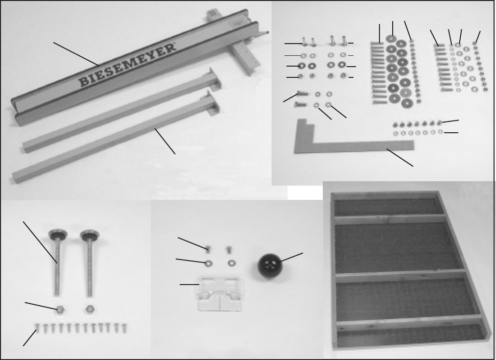
1. T-Square
®
Fence
2. Support Leg (2)
3. Leveling Foot (2)
4. 3/8-16 Hex Nut (2)
5. #8 x 5/8” Pan HD Screw (12)
6. #10-32 X 3/8” RND HD Screw (2)
7. Flat Washer (2)
8. Hairline Pointer
9. Knob
For Attaching Front Rail to Delta Unisaw/Contractor
Saw/Hybrid Saw
10. 5/16-18 x 1-1/4” Flat HD Screw (2)
11. 3/8 Lock Washer (2)
12. 3/8 Flat Washer (2)
13. 5/16-18 Hex Nut (2)
For Attaching Extension Table (All Saws)
18. 1/4-20 x 1-1/2” Flat HD Screw (14)
19. Fender Washer (14)
20. 1/4-20 Hex Nut (14)
For Attaching Front & Rear Rail to Non Delta Saws
21. 1/4-20 x 1-1/4” Flat HD Screw (10)
22. 1/4” Lockwasher (10)
23. 1/4” Flat Washer (10)
24. 1/4-20 Hex Nut (10)
For Attaching Guide Tube to Front Rail
25. 1/4-20 X 1/2” Hex HD Screw (7)
26. 1/4” Lock Washer (7)
27. Template
For Attaching Rear Rail to Delta Hybrid Saw and Left-Tilt
Contractor’s Saw ONLY
28. 8MM x 1” Hex HD Screw (2)
29. 8MM Lock Washer (2)
30. 8MM Flatwasher (2)
3
1
2
3
4
5
6
7
8
9
10
11
12
13
14
15
16
17
18 19 20
21 22 23 24
25
26
27
28
29 30
For Attaching Rear Rail to Delta Unisaw/Right-tilt
Contractors Saw
14. 3/8-24 x 1-1/4” Hex HD Screw (2)
15. 3/8 Lock Washer (2)
16. 3/8 Flat Washer (2)
17. 3/8-24 Hex Nut (2)
Fig. 2

CONSTRUCTING EXTENSION TABLE
ASSEMBLY (DELTA SAWS ONLY)
FOR ALL OTHER SAWS, PROCEED
DIRECTLY TO PAGE 7, STEP 1.
DISCONNECT THE SAW FROM
THE POWER SOURCE!
FRONT RAIL TO SAW
1. Assemble front rail (A) Fig. 5 to the front edge of the saw
table using the two 5/16-18 x 1-1/4” long flat head Phillips
screw, flat washer, 3/8” lock washer and 5/16-18” hex nut (B)
supplied. Screws are inserted throught the two larger counter-
sunk holes in the front rail and into the two holes in the front of
the saw table and fastened with the flat washer, lock washer
and hex nut. IMPORTANT: Do not tighten front rail mounting
hardware at this time.
FOR DELTA CONTRACTORS & HYBRID SAWS ONLY
Hang the on/off switch from the front rail mounting bolt on the
left side of the saw, as shown in Fig. 6, before putting on the
flat washer, lock washer and hex nut.
2. Using template (C) Figs. 5 & 7, Check and adjust the front
rail on both sides of the saw blade as shown, to make sure the
rail is parallel with the table surface. The horizontal portion of
the rail should be down from the top of the table surface
2-27/32”. Tighten the front rail mounting hardware when
you are certain the rail is set at the proper depth.
4
Fig. 4
Fig. 5
Fig. 6
A
B
C

REAR RAIL FOR DELTA SAWS
NOTE: Do not use template to set rear rail.
3. Align the two non-countersunk holes in the rear rail with the
two holes in the rear edge of the saw table. The two cutouts in
the rear rail need to be below the bottom of the two miter slots
in the saw table. Fasten rear rail to the saw as follows:
For Delta Unisaw Thread the two 3/8-24 x 1-1/4” long hex
head screw, lock washer and flat washer (D), supplied, Fig. 8,
through the two holes in the rail and into the two threaded
holes in the saw table.
For Right-tilting Delta Contractor’s Saws Fasten rail to the
saw using the two 3/8-24 x 1-1/4” hex head screws, lock
washers, flat washers and hex nuts (E) supplied, Fig. 9. The
lock washer, flat washer and hex nut will be on the inside edge
of the saw table.
For Delta Hybrid Saw and Left-tilting Contractor’s Saw
Fasten rail to the saw using the two 8MM x 1” long hex head
screw, 8MM lock washer and 8MM flat washer supplied, Fig 8,
through the two holes in the rail and into the two threaded
holes in the saw table.
4. After fastening the rear rail to the saw table, tilt the saw
blade to make certain there is no interference between the
guard splitter and the rear rail. If there is, it will be necessary
to enlarge the cut-out (F), Fig. 9, in the rear rail.
TABLE LEGS TO TABLE BOARD
IMPORTANT: If your saw fence system will be used with a
mobile base underneath the saw base and table legs, the
position of the legs will have to be changed to fit the
mobile base extension.
5. Assemble the 3/8” jam nut (G) onto leveling screw (H).
Thread leveling screw into bottom of support leg. Fig. 10
illustrates the foot leveling assembly on the table leg. Assemble
the remaing foot assembly to the other leg in the same
manner. NOTE: Height adjustment will be made later.
D
Fig. 7
E
F
Fig. 8
G
H
Fig. 9
Fig. 10
5
A
C

6. Lay the table upside down on the floor or on a bench.
7. Position the table leg (I) to the closed in corner of the extension
table (J) as shown in Fig. 11.
8. Attach the table leg to the table board with six 5/8” long wood
screws (K). Repeat this process for the remaining leg.
IMPORTANT: If your saw fence system will be used with a
mobile base underneath the saw base and table legs, the
position of the legs will have to be changed to fit the mobile
base extension.
NOTE: Table shown installed on a Unisaw without the cast iron
wing. If your saw has a cast iron extension wing on the right
hand side, it is not necessary to remove the wing. The
extension table can extend past the rails and tube.
9. Place table assembly (L) Fig. 12, in position between the two
rails, as shown. Make sure end of table is flush against saw table
(M). Using a straight edge make sure table (L) is in the same plane
and level with saw table (M). Lightly tap up or down and adjust leg
leveling screws. When you are certain table (L) is level and in the
same plane with saw table (M) tighten bar clamp (P) to hold
everything in position. Then drill 1/4” holes through the front and
rear of the extension table using holes (Q) provided in rails as a
template. NOTE: Number of holes (Q) in the front and rear rails will
vary depending on the length of the rails you purchased.
10. After the holes have been drilled in the edge of the front and rear
extension table board, fasten both front and rear rail to table using
the 1/4-20 x 1-1/2” flat head Phillips screws, 1-1/4” O.D. flat
washers and hex nuts (R).
11. Lay the guide tube (B) Fig. 14, on the saw table as shown, and
line up the threaded holes (S) on the bottom of guide tube with the
through holes (T) on the front rail. NOTE: The guide tube should
extend past the rail 6” on each end.
12. Position the guide tube (B) on the front rail and fasten the guide
tube to the rail using the 1/4-20 x 1/2” long hex head screws and
lock washers. NOTE: Where there are two holes 2-1/2” apart, use
only one of the two holes.
PROCEED TO STEP ONE ON PAGE 9
Fig. 11
L
M
Q
P
R
Fig. 12
Fig. 13
6
B
S
R
Fig. 14
I
J
K

ASSEMBLY (FOR ALL OTHER SAWS)
DISCONNECT THE SAW FROM THE POWER
SOURCE!
ASSEMBLE FRONT RAIL
1. Raise saw blade (A) Fig. 15. Place a straight edge (B)
against the right side of saw blade extending out over the
front of the saw as shown. Position front rail (C) against
the edge of saw table and lightly clamp in place using bar
clamps (D). Align notch (E) in front rail (C) with the straight
edge (B) as shown. NOTE: Any portion of the notch
needs to align with the straight edge. Final
calibration will be explained later.
2. Using template (F) Fig. 16, check and adjust the front
rail at both sides of saw table, to make sure the horizontal
portion of front rail (C) is parallel with the table top and
then tighten bar clamps. The rail should be down from
the top of the table 2-27/32”.
3. When you are certain front rail (C) is level with the table
surface, drill four 1/4” through holes into the saw table
using the 1/4” counter sunk holes in the front rail as a
template. IMPORTANT: Before drilling, check to make
certain there is no interferance such as casting ribs
behind front edge of saw table.
4. Fasten front rail (C) to saw table using the four 1/4-20 x
1-1/4” long flat head screws, flat washers, lock washers
and hex nuts supplied.
ASSEMBLE REAR RAIL
5. Clamp rear rail (G) Fig. 17, to back of saw table using
bar clamps making certain notch (E) in rail is aligned with
saw blade (A) as shown, using straight edge (B). Make
sure the two cutouts in the rail are below the bottom of the
miter slots in the saw table.
6. Check to make certain there are no interferance such
as casting ribs behind the rear edge of the saw table and
drill a minimum of two through holes into the saw table
using the countersunk holes as a template. Fasten rear
rail to saw table using the 1/4-20 x 1-1/4” long flat head
screws, flat washers, lock washers and hex nuts supplied.
IMPORTANT: If there is no room in rear edge of the
table to drill through holes, it will be necessary to drill
#7 holes and tap holes with a 1/4-20 tap.
7. After fastening the rear rail to the saw table, tilt the saw
blade to make certain there is no interferance between
the saw guard and the rear rail. If there is, it will be
necessary to enlarge the cut-out (H) Fig. 17, in the rear
rail.
EXTENSION TABLE & SUPPORT LEGS
8. Assemble the 3/8” jam nut (I) onto leveling screw (J).
Thread leveling screw into foot adapter. Fig. 18 illustrates
the foot leveling assembly on the table leg. Assemble the
remaining foot assembly to the other leg in the same
manner. NOTE: Height adjustments will be made later.
Fig. 16
Fig. 15
Fig. 17
Fig. 18
I
J
A
B
C
D
E
F
C
A
B
G
E
H
7

IMPORTANT: If your saw fence system will be used
with a mobile base underneath the saw base and table
legs, the position of the legs will have to be changed
to fit the mobile base extension.
9. Lay the extension table upside down on a floor or bench.
10. Position table leg (K) to the closed in corner of the
extension table (L), as shown in Fig. 19.
11. Attach the table leg (K) to the table board (L) with six
5/8” long wood screws (M). Repeat this process for the
remaining leg.
IMPORTANT: If your saw fence system will be used
with a mobile base underneath the saw base and table
legs, the position of the legs will have to be changed
to fit the mobile base extension.
12. Place table assembly (L) in position between the front
and rear rail, as shown in Fig. 20. Make sure end of table
is flush against saw table and using a bar clamp, snug up
ends of rails to hold table in position. Using a straight edge,
(N), make certain table is in the same plane and level with
saw table. Adjust leveling screws in bottom of support legs
to accomplish this. When you are certain table is level
and in the same plane as the saw table, tighten bar clamp
to hold everything in position. Then drill 1/4” through holes
through the front and rear table frame using holes (O) in
the rail as a template. The number of holes to drill will
depend on the length of the rails.
13. After the holes have been drilled in the front and rear
table frame, fasten both front and rear rail to table Fig. 21
using the 1/4-20 x 1-1/2” long flat head screws, fender
washers and hex nuts (P) provided.
14. Lay guide tube (Q) Fig. 22, on saw table as shown,
and line up the threaded holes (R) in bottom of guide tube
with through holes (S) in the front rail. Guide tube will
extend 6” past the rail at both ends.
15. Lay guide tube on front rail and fasten the guide tube
to the front rail using the 1/4-20 x 1/2” long hex screws
and lockwashers provided. NOTE: Where there are two
holes 2-1/2” apart, use only one of the holes.
8
Fig. 19
Fig. 20
Fig.21
Fig. 22
K
L
M
L
N
O
P
Q
R
S

ASSEMBLY (FOR ALL SAWS)
1. Attach knob (A) Fig. 23 to locking handle (B). Knob is
screwed onto threads of locking handle.
2. Align fence side (C) Fig. 24, with the miter slot on the
table saw and lock fence in position. Using a measuring
tape (D), measure the distance from the saw blade to the
fence side.
3. WITHOUT MOVING THE FENCE, attach hairline
pointer (E), Fig. 25 to fence crossarm (F) using two
#10-32 x 3/8” round head screws and flat washers (G).
Screws go through the slotted holes in the pointer and
into the threaded holes (H) in the crossarm. Using the
measurement from Step 2, align the black line in the
pointer to the same measurement on the guide tube tape
and securely tighten screws.
IMPORTANT: CHECK TO MAKE CERTAIN THAT THE
MITER GAGE SLOTS IN THE SAW TABLE ARE
PARALLEL WITH THE SAW BLADE. CHECK WITH THE
INSTALLATION MANUAL THAT CAME WITH YOUR
SAW FOR INSTRUCTIONS.
4. The fence (C) Fig. 26, must be adjusted so it is parallel
to the miter gage slot. Slide the fence until the bottom
edge is in line with the edge of the miter gage slot as
shown and push down on locking handle (B). Check to
see if the fence (C) is aligned with the miter slot the entire
length of the table. If an adjustment is needed, lift fence
(C) off the guide as shown in Fig. 27. Slightly tighten or
loosen adjusting screws (J) or (K), using a 3/16” Allen
wrench (N), not included. Replace the fence on the guide
tube and check again. Repeat this adjustment until you
are certain the fence is parallel to the miter gage slot.
NOTE: Very little movement of the adjusting screws
is necessary to adjust the fence.
9
Fig. 23
Fig. 24
Fig. 25
Fig. 26
A
B
C
D
E
F
G
H
C
B

5. When the fence locking handle (B) Fig. 28, is pushed
to the down position, the fence assembly (C) should be
completely clamped to the guide tube. If the fence
assembly (C) is not completely clamped to the guide tube
when the handle is pushed down, as shown, lift up handle
(B) and raise fence off the guide tube as shown in Fig. 27.
Slightly tighten the two adjusting screws (J) and (K) (if the
fence is too loose) or loosen (if the fence is too tight),
using a 3/16” Allen wrench (N), not supplied. NOTE:
Screws (J) and (K) should be tightened or loosend an
equal amount. Replace the fence back on the guide tube
and recheck to see if the fence assembly is completely
tightened to the guide tube with the locking handle (B)
pushed down. Adjust further if necessary.
IMPORTANT: AFTER ADJUSTING THE FENCE
CLAMPING ACTION, RECHECK TO SEE THAT THE
FENCE IS STILL PARALLEL TO THE MITER GAGE
SLOT AND ADJUST AS NECESSARY.
6. When clamping the fence assembly (C) to the guide
tube, make certain the camfoot (P), Fig. 29, is hanging
down and against the locking handle (B), and not caught
on top of the guide tube.
7. To move the fence along the guide tube, simply lift up
the locking handle (B) Fig. 30, as shown, slide the fence
to the desired position on the guide, and push down
locking handle (B) Fig. 28 as shown, to lock in position.
NOTE: A magnet (R) Fig. 28, is provided to hold the handle
in the up position when moving the fence.
10
Fig. 27
Fig. 28
Fig. 29
Fig. 30
B
C
C
P
B
B
R
J
K
N

9. The distance the fence is positioned away from the saw
blade is indicated by the witness line (S) located in cursor (E),
Fig. 31. To calibrate the cursor to the saw blade, make a test
cut with the fence locked in position. Measure the width of the
cut piece. Adjust the cursor by loosening screws (G),
adjusting the cursor until the witness line is aligned with the
same marking on the scale as the cut piece. Tighten the two
screws (G). Repeat until the width of the cut piece matches
the measurement indicated by the witness line.
10. Apply grease to locking handle (B) and camfoot (P) Fig.
32, monthly to prevent wear.
11. Apply paste wax to the fence sides and the unpainted guide
tube sliding surfaces weekly. Meguiar’s Professional Past Wax
(M-2611) is recommended. Also, saw table and extension table
surface should be waxed.
11
Fig. 31
Fig. 32
B
P
S
E
G

Delta will repair or replace, at its expense and at its option, any new Delta machine,machine part, or machine accessory which in normal
use has proven to be defective in workmanship or material, provided that the customer returns the product prepaid to a Delta factory
service center or authorized service station with proof of purchase of the product within two years and provides Delta with reasonable
opportunity to verify the alleged defect by inspection. For all refurbished Delta product, the warranty period is 180 days, Delta may
require that electric motors be returned prepaid to a motor manufacturer’s authorized station for inspection and repair or replacement.
Delta will not be responsible for any asserted defect which has resulted from normal wear, misuse, abuse or repair or alteration made
or specifically authorized by anyone other than an authorized Delta service facility or representative. Under no circumstances will Delta
be liable for incidental or consequential damages resulting from defective products. This warranty is Delta’s sole warranty and sets
forth the customer’s exclusive remedy, with respect to defective products; all other warranties, expressed or implied, whether of
merchantability, fitness for purpose, or otherwise, are expressly disclaimed by Delta.
TWO YEAR LIMITED NEW PRODUCT WARRANTY
12
