SawStop
®
OWNER’S MANUAL
T-Glide
TM
Fence System-
Professional Series II
Model TGP2-FA

1. 1. You MUST install a rip fence before using your saw. Using the saw without a rip fence could result in
serious personal injury.
2. 2. Never perform a ripping operation freehand or a serious injury may result.
3. 3. Always use a push stick or push block when your hand comes within 6 inches of the blade. Attempting to use
the rip fence for narrow cuts without a push stick or push block could result in a serious injury.
4. 4. Do not use the miter gauge when making rip cuts.
5. 5. While making bevel cuts, use the fence only on the right side of the saw blade to prevent the blade from
possibly contacting the fence. The brake will activate if the spinning saw blade contacts the metal in the fence.
Safety
Warranty
SawStop warrants to the original retail purchaser of a new T-Glide Fence System - Professional Series II from
an authorized SawStop distributor that the fence system will be free from defects in material and workmanship
for ONE YEAR from the date of purchase. SawStop warrants to the original retail purchaser of a refurbished,
demonstration or oor model T-Glide Fence System - Professional Series II from an authorized SawStop distributor
that the fence system will be free from defects in material and workmanship for SIX MONTHS from the date of
purchase.
This warranty does not apply to defects arising from misuse, abuse, negligence, accidents, normal wear-
and-tear, unauthorized repair or alteration, or lack of maintenance. This warranty is void if the fence system or any
portion of the fence system is modied without the prior written permission of SawStop, LLC, or if the fence system
is located or has been used outside of the country where the authorized SawStop distributor from whom the fence
system was purchased resides.
Please contact SawStop to take advantage of this warranty. If SawStop determines the fence system is
defective in material or workmanship, and not due to misuse, abuse, negligence, accidents, normal wear-and-
tear, unauthorized repair or alteration, or lack of maintenance, then SawStop will, at its expense and upon proof
of purchase, send replacement parts to the original retail purchaser necessary to cure the defect. Alternatively,
SawStop will repair the fence system provided it is returned to SawStop, shipping prepaid, with proof of purchase
and within the warranty period.
SawStop disclaims any and all other express or implied warranties, including merchantability and tness for a
particular purpose. SawStop shall not be liable for death, injuries to persons or property, or incidental, consequential,
contingent or special damages arising from the use of the fence system.
This warranty gives you specic legal rights. You may have other rights which, in the United States, vary from
state to state.
Page 2
| SawStop T-Glide Fence System - Professional Series II
SawStop
SawStop
®
OWNER’S MANUAL
T-Glide
TM
Fence System-
Professional Series II
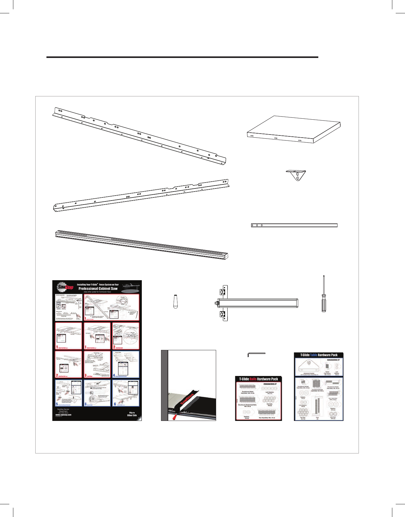
Unpacking Your T-Glide Fence System
While unpacking your saw, verify that you have all the components shown below for your specic fence system.
The T-Glide Fence System – Professional Series II is available in either a 52” system or a 36” system. Although the
components pictured below are from the 52” system, the components from the 36” system are similar.
Front Rail
Extension Table
Rear Rail
Support Leg (2)
Main Tube
Fence Handle
Owner’s Manual
T-Glide Fence
5 mm Hex Key
Leg Support
Bracket (2)
5 mm Ball-End
Hex Driver
T-Glide Rails
Hardware Pack
T-Glide Table
Hardware Pack
Installation Poster
(One for a Professional Cabinet Saw
and another for a Contractor Saw)
Fig. 1
Page 3
| SawStop T-Glide Fence System - Professional Series II

Note: Your saw must be fully assembled before installing the fence system.
Note: The drawings below show how to assemble both the 52” and 36” fence systems. Although the
components shown are from the 52” fence system, the components from the 36” system are similar.
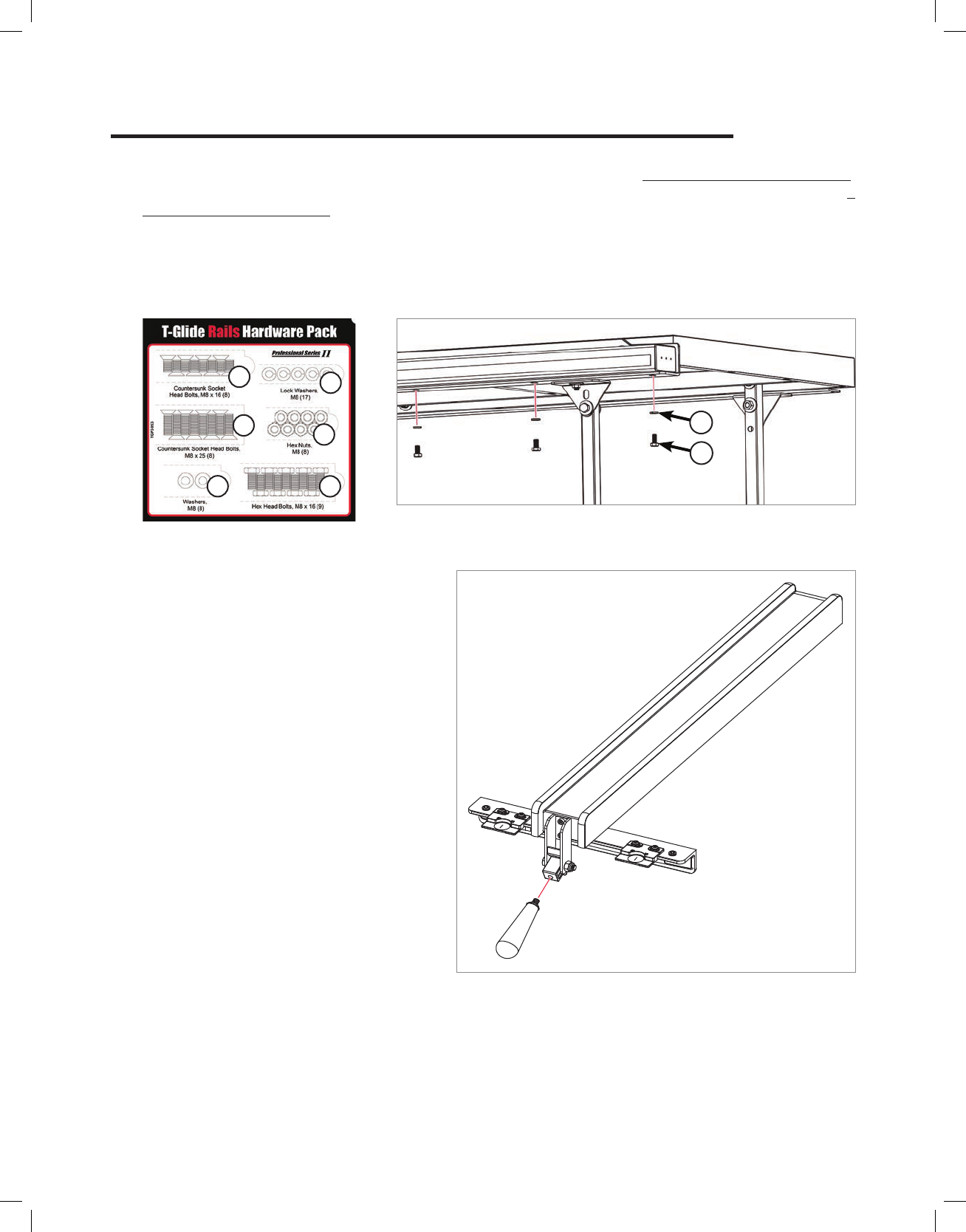
Before you begin installing the fence system, locate the front rail, the rear
rail, and the T-Glide Rails Hardware Pack (). All of the hardware needed
to install the rails is located on the T-Glide Rails Hardware Pack and is
shipped in the T-Glide fence box. In order to easily identify the hardware
used in each of the following steps, the dierent pieces of hardware are
numbered on the hardware pack and in the gures. If you are missing the
T-Glide Rails Hardware Pack, the T-Glide Table Hardware Pack, or any
of the other fence system components shown in Fig. 1, call the SawStop
Service Department at 503-582-9934.
You will also need the following tools to complete the fence assembly:
• 13 mm wrench
• 17 mm wrenches (2) (or adjustable wrenches)
• 5 mm hex key
• Level or straight-edge
The instructions for installing rails on a SawStop Professional Cabinet Saw are dierent from the instructions for
a SawStop Contractor Saw. The instructions for installing the extension table are the same for the Professional
Cabinet Saw and the Contractor Saw.
If you have a SawStop Professional Cabinet Saw
- Begin on page 3.
If you have a SawStop Contractor Saw
- Begin on page 8.
Fig. 2
1
2
3
4
5
6
Page 4
| SawStop T-Glide Fence System - Professional Series II
Installing Your T-Glide Fence System

Installing Your T-Glide Fence System
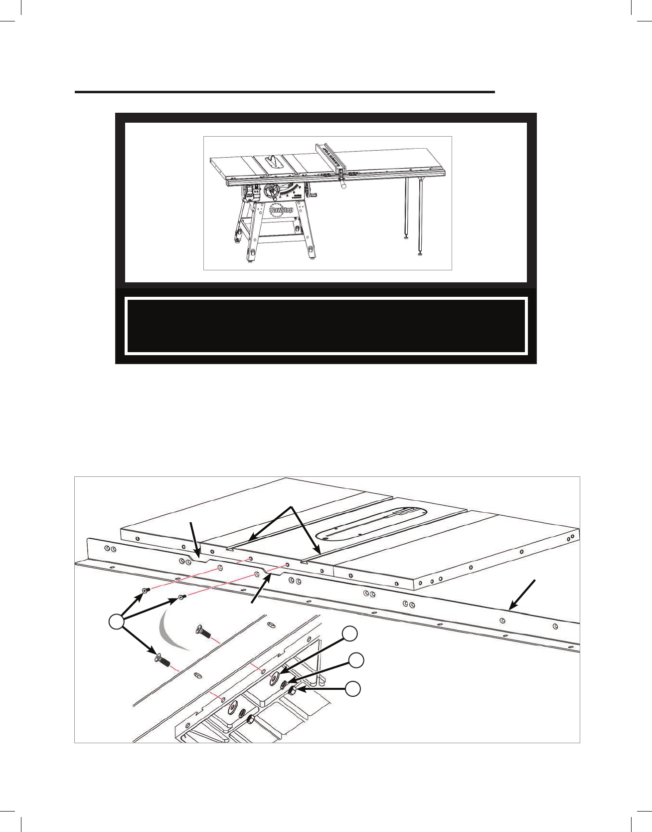
Miter slots
Front rail
Use M8 x 16 bolts
1. Begin mounting the front rail (the longer of the two rails) to the front edge of your saw by centering the notches
in the rail with the two miter slots in the table, aligning the two holes in the rail between the notches with the
two corresponding holes in the front edge of the table, and threading an M8 x 16 countersunk socket head bolt
(1) into each hole (See Fig. 3). Aligning the two holes between the notches aligns all the other holes used in
mounting the rail to your saw. Not all the holes are used to mount the rail to your saw; dierent holes are used
for dierent saws. Thread the bolts into the corresponding holes, and tighten them using a 5 mm hex key.
Notch
Notch
Fig. 3
Installing your T-Glide
TM
Fence System on your
SawStop
®
Professional Cabinet Saw
1
Page 5 | SawStop T-Glide Fence System - Professional Series II

2. Take two more M8 x 16 countersunk socket head bolts (1) and thread one into the hole to the right of the
notches and the other into the hole to the left of the notches (See Fig. 4). Tighten the bolts with a 5 mm hex
key.
Installing Your T-Glide Fence System
Professional Cabinet Saw
1
Fig. 4
Page 6
| SawStop T-Glide Fence System - Professional Series II

Installing Your T-Glide Fence System
Professional Cabinet Saw
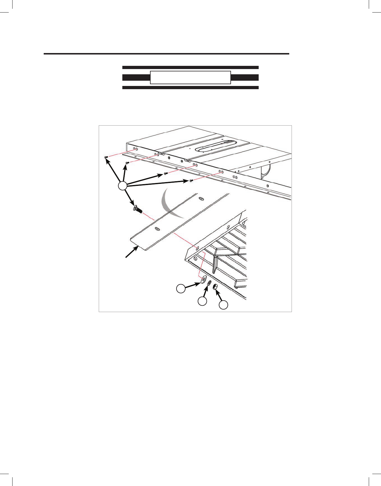
3. Take two M8 x 25 countersunk socket head bolts (2) and insert one bolt through the corresponding hole in the
end of each extension wing. Place an M8 washer (3), an M8 lock washer (4), and an M8 hex nut (5) on the
threaded end of each of the bolts (See Fig. 5). Hand tighten the nuts; do not fully tighten them.
2
Fig. 5
Front rail
2
5
3
4
Page 7
| SawStop T-Glide Fence System - Professional Series II

Installing Your T-Glide Fence System
Professional Cabinet Saw
Fig. 7
5. Finish mounting the rear rail to your saw by inserting an M8 x 25 countersunk socket head bolt (2) through the
open hole at the end of each extension wing, and placing an M8 washer (3), an M8 lock washer (4), and
an M8 hex nut (5) on the threaded end of each bolt (See Fig. 7). Hand tighten the nuts; do not fully tighten
them.
Rear rail
4. Begin mounting the rear rail (the shorter of the two rails) to the rear edge of your saw by centering the notches
in the rail with the two miter slots in the table and aligning the left-most hole between the notches with the
corresponding hole in the rear edge of the table (See Fig. 6). There are three holes in the rail between the
notches, one solitary hole and two holes paired together, and the left-most hole is the solitary hole. Not all the
holes are used to mount the rail to your saw; dierent holes are used for dierent saws. Aligning the left-most
hole aligns all the other holes used in mounting the rail to your saw. When the holes are aligned, mount the rail
to the saw by threading an M8 x 16 countersunk socket head bolt (1) into each of the four open holes in the
rear edge of the table and tighten the bolts using a 5 mm hex key.
Fig. 6
Rear rail
1
2
3
4
5
Page 8
| SawStop T-Glide Fence System - Professional Series II

6. Use a straight-edge to level the front edge of the left extension wing to the cast iron table top (See Fig. 8). You
may have to pull up or push down on the outer edge of the extension wing to level it. Once the front edge of
the left extension wing is level, use a 5 mm hex key and a 13 mm wrench to fully tighten the nut on the bolt that
mounts the left extension wing to the front rail. Repeat this process to level the front edge of the right extension
wing and the rear edges of the left and right extension wings.
Level the extension wing
and tighten the nut on the
bolt that goes through the
extension wing
Fig. 8
Straight-edge
Installing Your T-Glide Fence System
Professional Cabinet Saw
Page 9 | SawStop T-Glide Fence System - Professional Series II
Installing Your T-Glide Fence System
Miter slots
1. Begin mounting the front rail (the longer of the two rails) to the front edge of your saw by centering the notches
in the rail with the two miter slots in the table, aligning the two holes in the rail between the notches with the two
corresponding holes in the front edge of the table, and inserting an M8 x 25 countersunk socket head bolt (2)
into each hole. Aligning the two holes between the notches aligns all the other holes used in mounting the rail
to your saw. Not all the holes are used to mount the rail to your saw; dierent holes are used for dierent saws.
Insert the bolts one at a time, placing an M8 washer and an M8 lock washer on the threaded end of each bolt
and then threading on an M8 hex nut (See Fig. 9). Hand tighten the nuts; do not fully tighten them.
Fig. 9
Front rail
Notch
Notch
Use M8 x 25 bolts
Installing your T-Glide
TM
Fence System on your
SawStop
®
Contractor Saw
5
4
3
2
Page 10
| SawStop T-Glide Fence System - Professional Series II
2. Take four more M8 x 25 countersunk socket head bolts and insert them through the four open holes in the front
rail and table. Place an M8 washer and an M8 lock washer on the threaded end of each of the bolts and then
thread an M8 hex nut on each bolt (See Fig. 10). Hand tighten the nuts; do not fully tighten them.
Contractor Saw
Fig. 10
Front rail
5
3
4
2
Page 11
| SawStop T-Glide Fence System - Professional Series II
Installing Your T-Glide Fence System

Rear rail
4. Begin mounting the rear rail (the shorter of the two rails) to the rear edge of your saw by centering the notches
in the rail with the two miter slots in the table and aligning the left-most hole between the notches with the
corresponding hole in the rear edge of the table. There are three holes in the rail between the notches, one
solitary hole and two holes paired together, and the left-most hole is the solitary hole. Not all the holes are used
to mount the rail to your saw; dierent holes are used for dierent saws. Aligning the left-most hole aligns all
the other holes used in mounting the rail to your saw. When the holes are aligned, mount the rail to the saw
by threading an M8 x 16 countersunk socket head bolt into each of the four open holes in the rear edge of the
table and tighten the bolts using a 5 mm hex key (See Fig. 12).
Fig. 12
Contractor Saw
1
Page 12 | SawStop T-Glide Fence System - Professional Series II
Installing Your T-Glide Fence System
Level the top of
the front rail with
the lower edge
of the bevel
Bevel
Tighten
Fig. 11
3. The holes in the front edge of the table and extension wings are slightly larger than the bolts they receive to
allow you to level the front rail and extension wings to the table top. Align the top of the front rail with the lower
edge of the bevel on the front edge of the table top (See Fig. 11). Use a 5 mm hex key and a 13 mm wrench
to fully tighten the nuts on the back of the four bolts that extend through the table top. Do not tighten the nuts
on the bolts that extend through the extension wings.

Installing Your T-Glide Fence System
Contractor Saw
5. Finish mounting the rear rail to your saw by inserting an M8 x 25 (2) countersunk socket head bolt through the
open hole at the end of each extension wing, and placing an M8 washer, an M8 lock washer, and an M8
hex nut on the threaded end of each bolt (See Fig. 13). Hand tighten the nuts; do not fully tighten them.
Level the extension
wing and tighten the
nut on the bolt that
goes through the
extension wing
Fig. 14
6. Use a straight-edge to level the front edge of the left extension wing to the cast iron table top (See Fig. 14). You
may have to pull up or push down on the outer edge of the extension wing to level it. Once the front edge of
the left extension wing is level, use a 5 mm hex key and a 13 mm wrench to fully tighten the nut on the bolt that
mounts the left extension wing to the front rail. Repeat this process to level the front edge of the right extension
wing and the rear edges of the left and right extension wings.
Straight-edge
Fig. 13
Rear rail
2
3
4
5
Page 13
| SawStop T-Glide Fence System - Professional Series II

7. Once the rails are in place you can mount the extension table to the
rails. The hardware needed to mount the extension table to the rails is
in the T-Glide Table Hardware Pack (See Fig. 15).
The rst step in mounting the extension table is to install the adjustment
bracket (13) included in the T-Glide Table Hardware Pack. Remove
the adjustment bracket, two M6 x 18 socket cap screws (14), and two
M6 lock washers (15) from the T-Glide Table Hardware Pack, and
place a lock washer on each screw. One end of the extension table
includes two holes and the adjustment bracket has two corresponding
holes. Position the adjustment bracket against the inside edge of the
extension table, align the holes, and thread the screws into the holes
(See Fig. 16). Tighten the screws with a 5 mm hex key.
The instructions for installing the extension
table and the fence (steps 7-22) are the same
for both the Professional Cabinet Saw and the
Contractor Saw.
Fig. 16
Fig. 15
Fig. 17
13
NOTE: The adjustment
bracket is designed for
cast iron wings only.
If you have a Contractor
Saw with stamped wings,
you may skip this step
and go on to step 8.
Stamped
Wing
25
24
23
22
20
16
13
14 15
17
18
19
21
14
15
Page 14
| SawStop T-Glide Fence System - Professional Series II
Installing Your T-Glide Fence System

Installing Your T-Glide Fence System
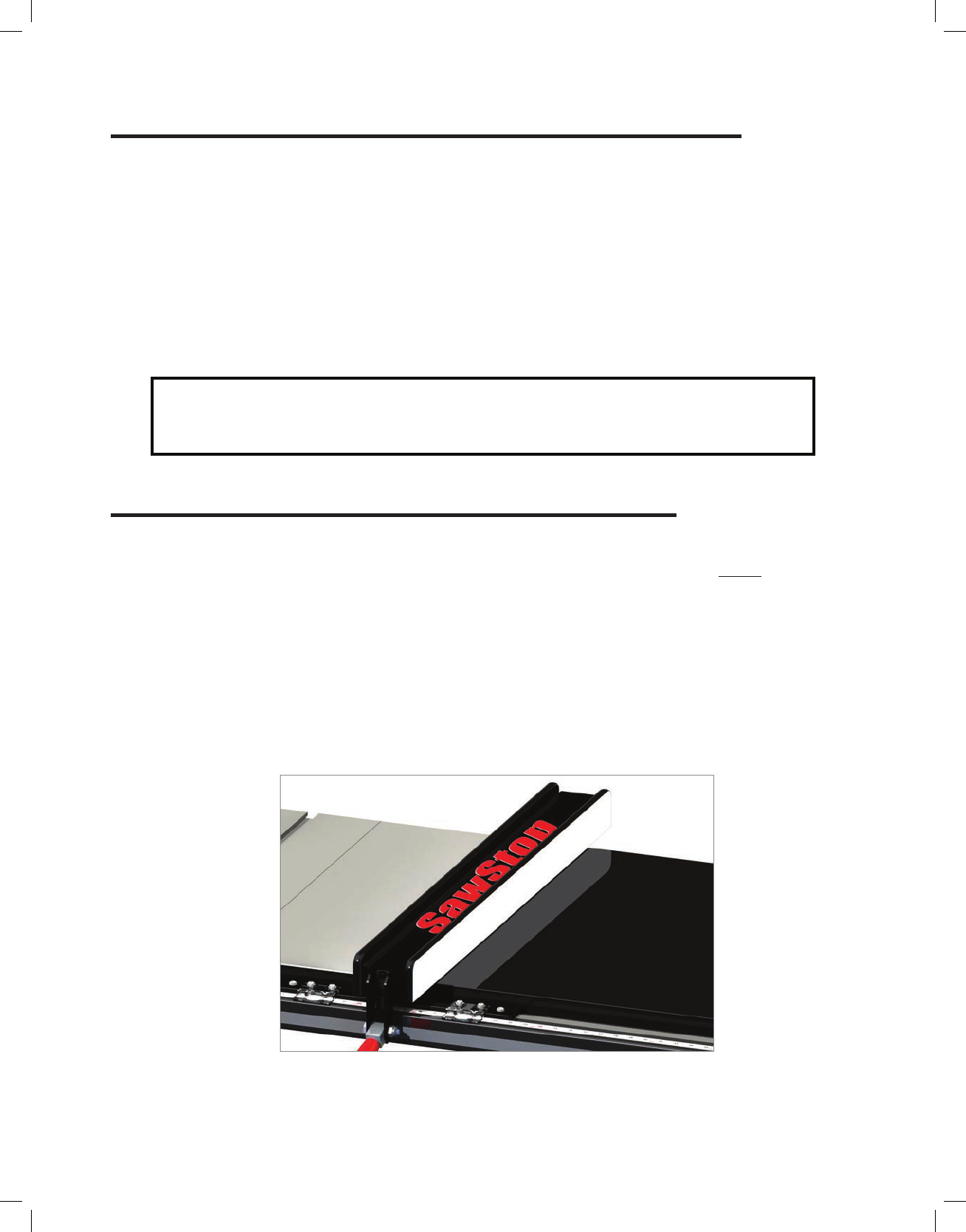
8. Locate the two leg support brackets. Remove the two M8 x 20 countersunk socket head bolts (16) from the
T-Glide Table Hardware Pack along with two M8 washers (17), two M8 lock washers (18) and two M8 hex nuts
(19). Mount one leg support bracket to the underside of each of the rails (See Fig. 18). Hand tighten the nuts;
do not fully tighten them.
Once mounted, the brackets should create a shelf as shown in the detail view of Fig. 18.
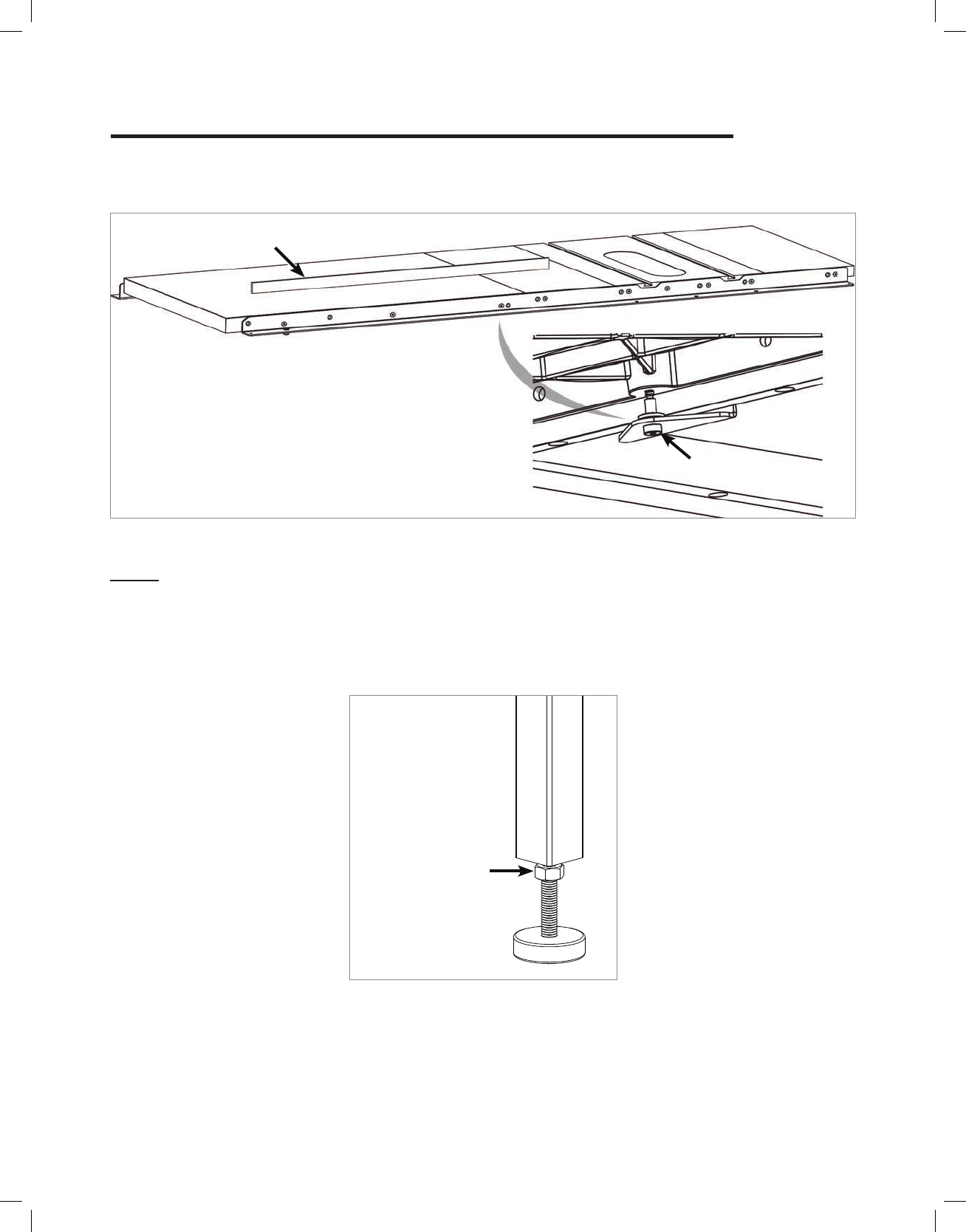
9. Place the extension table between the rails and slide it towards the extension wing (See Fig. 19). Be careful
when positioning the extension table because it is not yet secured to the rails and could fall. You will need to tilt
the extension table slightly for the adjustment bracket to t under the extension wing. The adjustment bracket
includes a screw that extends upward and the underside of the extension wing includes a hole to receive the
screw. Fit the screw into the hole, and then turn the screw until the extension table is roughly ush with the
extension wing. The opposite end of the extension table will rest upon the leg support brackets but will not be
level because the leg support brackets are at dierent elevations and are not intended to support the extension
table once it is fully installed.
Fig. 19
Leg Support
Bracket
Fig. 18
16
19
18
17
Page 15
| SawStop T-Glide Fence System - Professional Series II

Installing Your T-Glide Fence System
10. The extension table mounts to the rails with bolts that pass through holes in the rails and extension table (See
Fig. 20). If you have an extension table for a 36” fence system, take two M8 x 35 countersunk socket head bolts
and insert one through the hole in the front rail closest to the saw and the other through the hole in the rear
rail closest to the saw. If you have an extension table for a 52” fence system, take four M8 x 35 countersunk
socket head bolts and insert one bolt into each of the two holes in the front rail closest to the saw, and one
bolt into each of the two holes in the rear rail closest to the saw.
11. Locate the two support legs and remove the two feet from the T-Glide Table Hardware
Pack along with two M8 hex nuts. Thread an M8 hex nut onto the threaded shaft of
each foot so that the nut is close to the rubber base, and then thread the foot into the
bottom of the support leg as far as possible (See Fig. 21).
Fig. 21
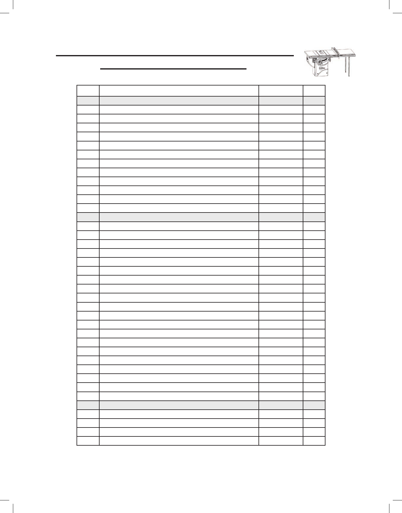
12. The support legs attach to the outer ends of the rails and extension table with M8 x 65 countersunk socket
head bolts. Align the top hole in one support leg with the outermost hole in the front rail, and the top hole in
the second support leg with the outermost hole in the back rail. Make sure the legs are positioned against the
inside of the extension table. Insert an M8 x 65 bolt through the holes in the rails, extension table and legs.
Place an M8 washer and an M8 lock washer on the threaded end of each bolt and then thread an M8 hex nut
onto each bolt (See Fig. 22). Hand tighten the nuts; do not fully tighten them.
Support leg
Fig. 20
20
21
19
17
18
22
19
Fig. 22
Place an M8 washer,
an M8 lock washer, and
an M8 hex nut on the
threaded end of each
bolt and hand tighten the
nuts. Do not insert bolts
through the outermost
holes in the front and
rear rails at this time.
17
18
19
Page 16
| SawStop T-Glide Fence System - Professional Series II

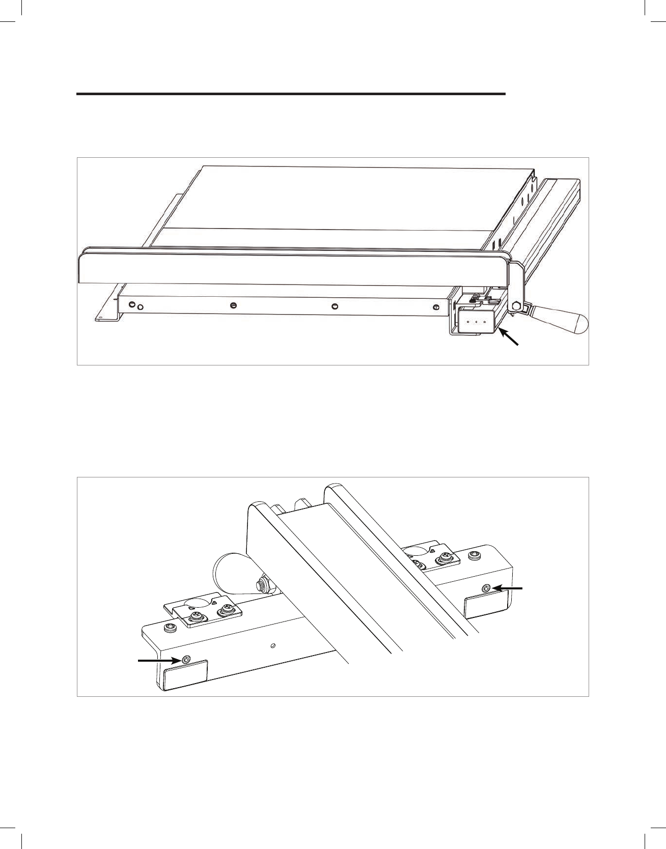
13. Attach each support leg to the corresponding leg support bracket with an M10 x 40 hex head bolt, two M10
washers, and an M10 lock nut, as shown in Fig. 23, and fully tighten the bolts using two 17 mm wrenches. Note
that the leg support brackets align with dierent holes in the front and rear legs because the brackets are at
dierent elevations.
Installing Your T-Glide Fence System
Straight-edge
Fig. 24
Fig. 23
14. Use a straight-edge to level the front edge of the extension table to the saw table (See Fig. 24). You may have
to pull up or push down on the extension table to level it. Once the front edge of the extension table is level,
use a 5 mm hex key and a 13 mm wrench to fully tighten the nuts on the bolts along the front rail. Repeat the
process to level the rear edge of the extension table. Also fully tighten the bolts that attach the leg support
brackets to the front and rear rails (bolts in step 8).
16
Front
Rail
Make sure to tighten the bolts that
attach the leg support brackets to
the front and rear rails
16
23
24
24
25
23
24
24
25
Rear
Rail
Page 17 | SawStop T-Glide Fence System - Professional Series II
15. Place the straight-edge lengthwise across the middle of the table and level the middle of the extension table
by turning the screw in the adjustment bracket with a 5 mm hex key (See Fig. 25).
Installing Your T-Glide Fence System
16. Turn the foot on the bottom of each support leg to adjust its position until it is in solid contact with the ground.
Once the foot is in contact with the ground, fully tighten the hex nut against the bottom of the leg using a
13 mm wrench (See Fig. 26).
Fig. 25
Fig. 26
Straight-edge
Adjust the position of
the foot and tighten
the hex nut
Adjustment screw
NOTE: The adjustment bracket is designed for cast iron wings only. If you have a Con-
tractor Saw with stamped wings, you may skip this step and go on to step 16.
Page 18 | SawStop T-Glide Fence System - Professional Series II
SawStop
Installing Your T-Glide Fence System
18. Locate the fence and the red fence handle.
Thread the handle into the cam lock on the
front of the fence (See Fig. 29).
17. Locate the main tube and the T-Glide Rails Hardware Pack (See Fig. 27). If you have a 36” fence system,
remove seven M8 x 16 hex head bolts and seven M8 lock washers from the T-Glide Rails Hardware Pack. If
you have a 52” fence system, remove nine M8 x 16 hex head bolts and nine M8 lock washers from the T-Glide
Rails Hardware Pack. Position the tube on the front rail with the rulers facing up and the 12-inch ruler on the
left. The powder coated surfaces of the tube and rail can be slick, so be careful that the tube does not fall o
the rail. Align the holes in the rail with the holes in the bottom of the tube. Place an M8 lock washer on each
M8 x 16 hex head bolt and insert the bolts through the rail and into the threaded holes in the bottom of the tube
(See Fig. 28). Hand tighten the bolts; do not fully tighten them.
Fig. 28
Fig. 27
Fig. 29
4
6
Thread the handle into
the cam lock
1
2
3
4
5
6
Page 19
| SawStop T-Glide Fence System - Professional Series II
Installing Your T-Glide Fence System
Parallelism
adjustment
screw
Front tube
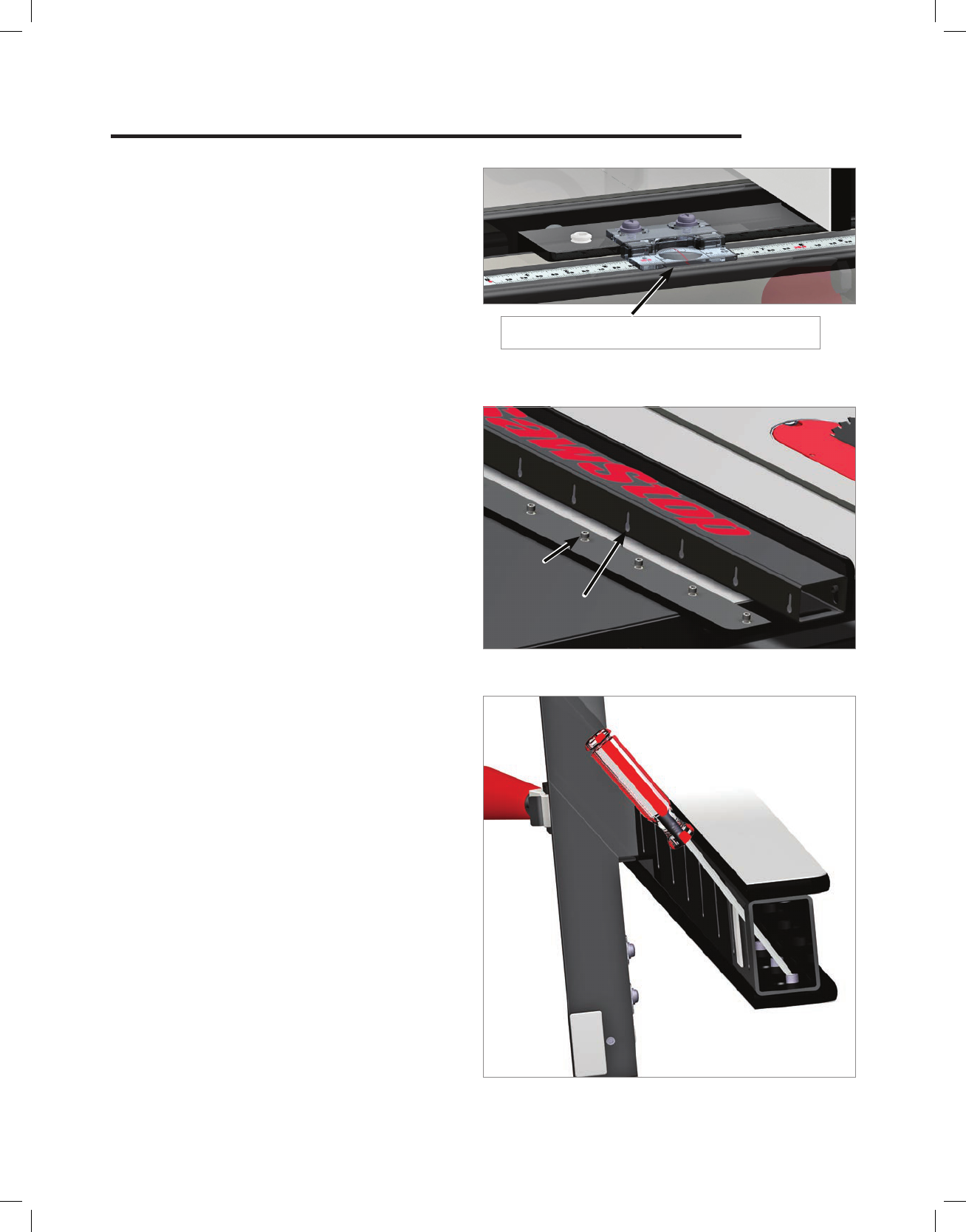
20. Press down on the fence handle to clamp the fence to the front tube. If the fence does not clamp tightly enough
to hold its position against a moderate amount of force, you can increase the clamping pressure by turning
both parallelism adjustment screws clockwise using a 5 mm hex key. Those screws are located in the vertical
portion of the fence cross-bracket (See Fig. 31). Alternatively, if too much force is required to push the fence
handle down to clamp the fence to the front tube, you can reduce the clamping pressure by turning both
parallelism adjustment screws counter-clockwise.
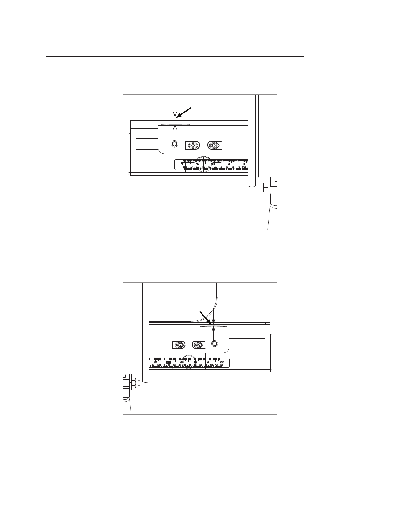
19. The holes in the bottom of the front rail are oversized to allow you to adjust the position of the tube on the rail.
To set the tube in the correct position, rst pull the front tube away from the table as far as possible. Next, place
your fence down on the tube near the left end (See Fig. 30).
Fig. 30
Parallelism
adjustment
screw
Fig. 31
Page 20 | SawStop T-Glide Fence System - Professional Series II
Installing Your T-Glide Fence System
Gap
22. Next, move the fence to the right end of the tube, repeat the above process to position the tube, and tighten
the right-most screw (See Fig. 33). Once both ends of the tube are adjusted correctly, tighten the remaining
M8 x 16 hex head bolts to mount the front tube to the front rail. The fence should now slide smoothly along the
front tube without binding and without excessive play.
21. Once the fence is tightly clamped to the front tube, move the left end of the tube back toward the saw until
there is only a small gap (approximately 1/32 inch) between the front rail and the rear of the fence (See Fig.
32). Tighten the left-most M8 x 16 hex head bolt that holds the tube to the front rail using a 13 mm wrench.
Fig. 33
Fig. 32
Gap
Page 21 | SawStop T-Glide Fence System - Professional Series II

Adjusting Your T-Glide Fence System
Fig. 34
Right indicatorLeft indicator
i. The fence allows you to precisely set the width of your rip cuts (cuts that are length-wise along the grain of the
wood).The precise width of cut is shown by the indicator lenses on the front of the fence (
See Fig. 34). The
lens on the left indicates the width of cut when the fence is on the left side of the blade. The lens on the right
indicates the width of cut when the fence is on the right side of the blade. Each indicator lens is positioned
above a ruler on the front tube. Each lens has a red cursor line that indicates the precise width of cut. To read
the width of cut, look down at the cursor line. The mark on the ruler that is directly below the cursor line is the
width of cut.
i. Although the fence is factory-adjusted to nominal settings, it is usually necessary to make nal adjustments
once your rails and extension table have been installed on the saw.
Page 22 | SawStop T-Glide Fence System - Professional Series II
i. If necessary, you can adjust the position of the indicator lenses on the front of the fence. To verify the position
of each indicator lens, clamp the fence to the front tube and use a ruler to measure the distance from the blade
to the fence plate and compare it to the measurement shown on the proper indicator lens. If adjustment is
necessary, loosen the two Phillips screws shown in
Fig. 35 and slide the indicator lens to the right or left until
the cursor is directly over the correct measurement. Tighten the screws to lock the position of the indicator
lens.
Adjust the indicator
lens by loosening the
two Phillips screws
Fig. 35

Adjusting Your T-Glide Fence System
i. The next step is to align the face plates to be
parallel to the miter slots. Begin by sliding the
fence along the front tube until the left face
plate is ush with the right edge of the right
miter slot. Lock the fence handle and check
that the face plate is ush with the miter
slot edge along its whole length (
See Fig.
36). You can check this either visually or by
running your nger along the face plate and
miter slot edge. If there is any misalignment,
you can correct it by turning one of the two
parallelism adjustment screws in the vertical
edge of the fence cross-bracket (
See Fig.
31).
Fig. 36
Fig. 37
Leveling
screw
i. To adjust the angle of the face plates, place
a combination square on the table top and
against the left face plate (
See Fig. 38). Use
a 6 mm hex key to adjust the leveling screws
as necessary until the face plate is parallel to
the vertical edge of the combination square.
i. The next step is to adjust the face plates to
be perpendicular to the table top. The angle
between the face plates and the table is
set by the two plastic leveling screws in the
horizontal portion of the cross-bracket (
See
Fig. 37). The leveling screws raise and lower
each end of the horizontal portion of the fence
cross-bracket with respect to the main tube
while the two face plates remain parallel with
each other. Adjusting the leveling screws tilts
the fence cross-bracket as needed to make
the face plates perpendicular to the table.
Fig. 38
Page 23 | SawStop T-Glide Fence System - Professional Series II
Adjusting Your T-Glide Fence System
i. It is usually possible to adjust the position
of the face plates by placing a small block
of wood against the top or bottom edge of
the face plates, and then tapping the block
of wood with a plastic or wooden mallet.
However, if the face plates do not move when
tapped, you can loosen the mounting screws
as described below to adjust the face plates.
ii. You can access the screws that attach the
face plates to the fence through the slots on
the bottom of the fence. Insert a 5 mm ball-
end hex driver through the slot at the end
of the fence and into the screw head (
See
Fig. 41) with endcap removed). Loosen the
screw about one-quarter to one-half turn. Do
not loosen the screw too much. The screw
should be just loose enough to allow the plate
to move but still tight enough to hold the plate
temporarily in its new position. Continue this
process with each slot/screw pair. Once all
the screws on one face plate are loose, slide
the face plate toward the top of the fence.
i. The last step is to set the spacing between
the bottom of each face plate and the table.
The face plates are held in place by a series
of screws threaded into nuts embedded in the
face plates. The heads of the screws t into
key-hole slots in the sides of the fence (
See
Fig. 40 with endcap removed).
Key-hole
slot
Screw
head
Fig. 40
i. You may nd that after adjusting the face
plates the end of the cross-bracket has been
raised or lowered such that it is too close or
too far away from the main tube. If this is the
case, turn both plastic leveling screws the
same amount in order to ensure the position
indicator lenses are close to, but not touching,
the front tube or rulers (
See Fig. 44).
There should be a gap between the position
indicator lens and the ruler on the main tube.
Fig. 44
Page 24 | SawStop T-Glide Fence System - Professional Series II
Fig. 41
Adjusting Your T-Glide Fence System
i. Install the fence on the front tube and position the face plate as desired, making sure to leave at least a small
gap between the bottom of the face plate and the table so the face plate does not drag on the table. It may
be necessary to loosen and raise the other face plate as well if it is too low and interferes with the adjustment.
ii. Next, carefully lift the fence off the front tube and place it on the table with the newly adjusted face plate facing
down. Make sure not to move the face plate from the position you set. If necessary you can clamp the face
plate to the fence to keep the face plate from moving. Tighten each screw to lock the face plate in position.
Make sure not to over-tighten these screws as that may cause a slight concavity in the surface of the face
plate near the screw.
iii. Now adjust the position of the other face plate if necessary.
Congratulations, your fence system is now
installed and your saw is ready to use.
Using Your T-Glide Fence System
i. The rip fence included with your T-Glide Fence System is used to guide material parallel to the blade when you
make rip cuts (cuts that are length-wise along the grain of the wood). The fence must always be used when
making rip cuts.
ii. To use the rip fence, begin by placing it on the table so that the fence bracket is resting on the upper rear edge
of the front tube. You can use the fence on either the left or right side of the blade for non-bevel cuts. If you
plan to make bevel cuts, use the fence only on the right side to prevent the blade from possibly contacting the
fence. After placing the fence on the rails, lift the red handle up to the unlocked position and slide the fence to
the left or right until the distance between the blade and the fence is approximately equal to the desired width
of cut. Adjust the position of the fence until the cursor on the indicator lens is directly over the desired width
of the cut. Use the lens on the left when the fence is on the left side of the blade and use the lens on the right
when the fence is on the right side of the blade. Once the fence is in the correct position, push the red locking
handle down to the locked position (
See Fig. 42). The fence is now locked in place and ready for use.
Fig. 42
Page 25 | SawStop T-Glide Fence System - Professional Series II

ATT ENTION
ATT ENTION
Never touch the blade during
coast down until the blade
stops completely and the
green light stops blinking.
Always check that the spacing
between the brake and the
blade is at least 1/16” after
every blade or brake change.
Always check that the
spreader or riving knife is at
least 1/4” from the blade.
Always run the saw in Bypa ss
mode when cutting metal or
conductive material.
FAILURE TO FOLLOW THESE
INSTRUCTIONS CAN RESULT IN
UNINTENDED BRAKE ACTIVATIONS.
CHECK OWNER’S MANUAL FOR DETAILS.
6
9
19
9
10
10
10
11
11
10
12
13
14
15
16
1
2
2
3
10
17
18
3
3
4
5
7
8
15
Fig. 43
Page 26
| SawStop T-Glide Fence System - Professional Series II
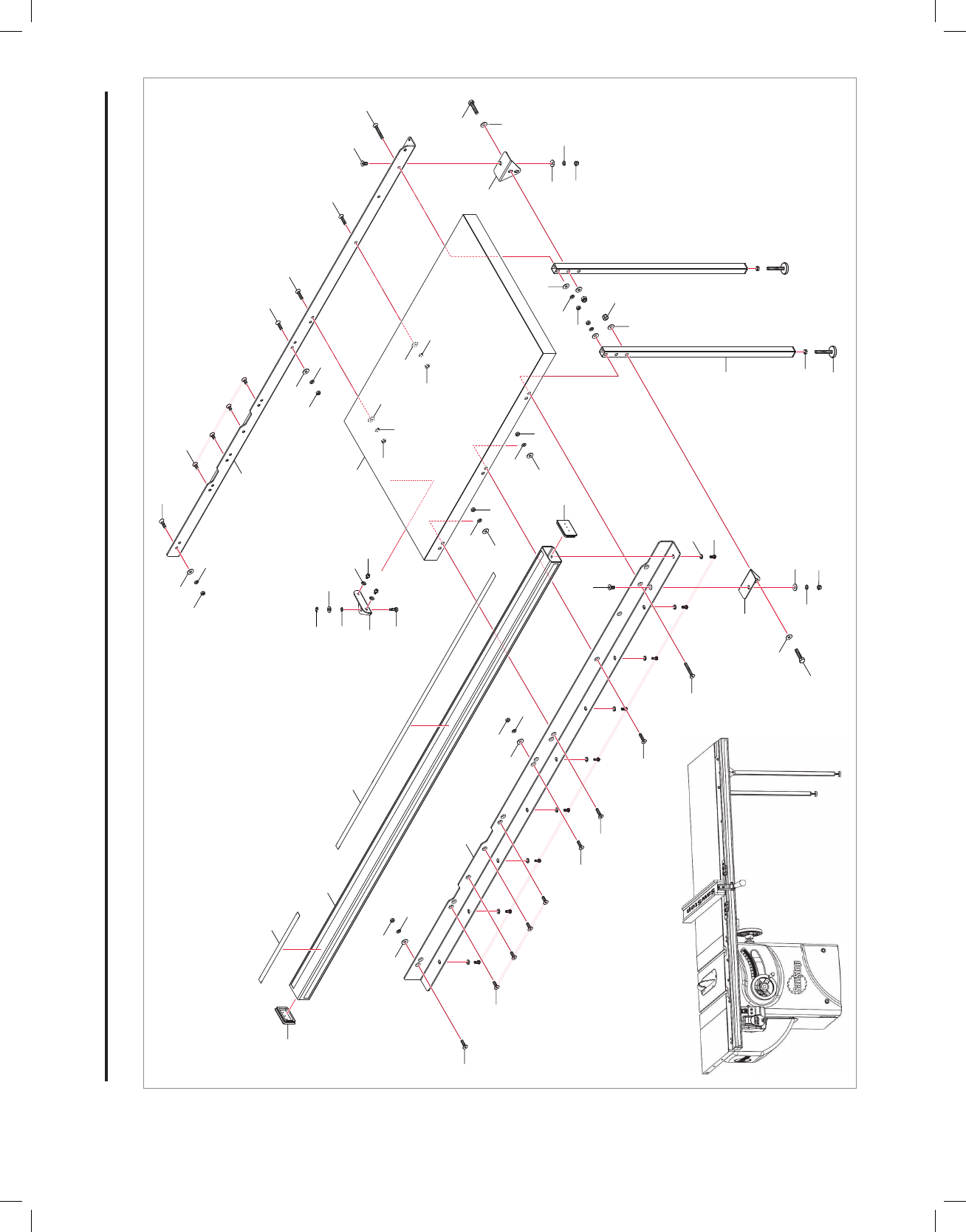
T-Glide Fence Exploded View

Page 27 | SawStop T-Glide Fence System - Professional Series II
No. Description Part No. Qty.
Professional Series II T-Glide Fence Assembly (items 1-18) TGP2-FA 1
1 Fence Tube TGP2-001 1
2 Face Plate TGP2-002 2
3 M6x1.0x10 Socket Head Screw TGP2-003 20
4 Handle TGP2-004 1
5 Cam Lock TGP2-005 1
6 M10x1.5x45 Hex Head Bolt TGP2-006 1
7 M10x1.5 Lock Nut TGP2-007 1
8 Flex Plate TGP2-008 1
9 Leveling Adjustment Screw M12x1.75 TGP2-009 2
10 Glide Plate TGP2-010 5
11 M10x1.5x10 Set Screw TGP2-011 2
12 Position Indicator Lens TGP2-012 2
13 M6x1.0x10 Pan Head Phillips Screw TGP2-013 4
14 M6x13x1.5 Washer TGP2-014 4
15 M6x1.0x8 Flat Head Phillips Screw TGP2-015 2
16 Flex Arm TGP2-016 1
17 SawStop Label TGP2-017 1
18 Fence Endcap TGP2-018 1
19 Fence Attention Magnet TGP2-075 1
Accessories
N/A 5 mm Ball-end Hex Driver TGP2-019 1
N/A 6 mm Hex Key TGP2-020 1
T-Glide Fence Parts List

Fig. 44
Page 28 | SawStop T-Glide Fence System - Professional Series II
28
23
21
25
24
24
23
24
19
7
8
26
27
27
6
4
10
18
18
18
17
17
17
19
19
19
2
20
22
16
16
1
22
2
20
5
3
4
5
3
4
18
17
2
1
9
11
12
4
5
2
3
4
5
3
13
29
31
30
32
14
17
18
19
19
15
10
36” Fence System Rails and Extension Table Exploded View for a Cabinet Saw
Page 29 | SawStop T-Glide Fence System - Professional Series II
36” Fence System Rails and Extension Table
Parts List for a Cabinet Saw
No. Description Part No. Qty.
Professional Series II 36” T-Glide Fence Rails (items 1-12) TGP2-R36A 1
1 M8x1.25x16 Countersunk Socket Head Bolt TGP2-021 8
2 M8x1.25x25 Countersunk Socket Head Bolt TGP2-022 4
3 M8x23x2 Washer TGP2-023 4
4 M8 Lock Washer TGP2-024 11
5 M8x1.25 Hex Nut TGP2-025 4
6 M8x1.25x16 Hex Head Bolt TGP2-026 7
7 36” Front Rail TGP2-027 1
8 36” Rear Rail TGP2-028 1
9 36” Main Tube TGP2-029 1
10 Main Tube End Cap TGP2-030 2
11 12” Ruler TGP2-031 1
12 36” Ruler TGP2-032 1
Professional Series II 36” T-Glide Extension Table
(items 13-32) TGP2-T36A 1
13 Adjustment bracket TGP2-033 1
14 M6x1.0x18 Socket Cap Screw TGP2-034 2
15 M6 Lock Washer TGP2-035 2
16 M8x1.25x20 Countersunk Socket Head Bolt TGP2-036 2
17 M8x23x2 Washer TGP2-037 6
18 M8 Lock Washer TGP2-038 6
19 M8x1.25 Hex Nut TGP2-039 8
20 M8x1.25x35 Countersunk Socket Head Bolt TGP2-040 2
21 Foot TGP2-041 2
22 M8x1.25x65 Countersunk Socket Head Bolt TGP2-042 2
23 M10x1.5x40 Hex Head Bolt TGP2-043 2
24 M10x25x1.5 Washer TGP2-044 4
25 M10x1.5 Lock Nut TGP2-045 2
26 36” Table TGP2-046 1
27 Leg Support Bracket TGP2-047 2
28 Support Leg TGP2-048 2
29 Adjustment Screw TGP2-049 1
30 M9x18.3x2.3 Washer TGP2-050 1
31 M9 Wave Washer TGP2-051 1
32 M8 Retaining Ring TGP2-052 1
Accessories
N/A T-Glide Rails Hardware Pack TGP2-053 1
N/A T-Glide Table Hardware Pack TGP2-054 1
N/A Professional Cabinet Saw Fence System Installation Poster TGP2-055 1
N/A T-Glide Fence System Professional Series II Owner’s Manual TGP2-056 1
1
9
11
12
2
2
10
10
3
5
4
3
4
2
1
5
3
4
5
5
3
4
20
20
16
27
2
20
20
17
17
17
18
18
18
19
17
18
19
17
18
19
19
19
26
13
29
31
30
32
8
22
16
14
15
22
27
17
18
19
28
23
21
24
23
24
24
19
25
7
18
17
19
4
6
Fig. 45
Page 30 | SawStop T-Glide Fence System - Professional Series II
52” Fence System Rails and Extension Table Exploded View for a Cabinet Saw
Page 31 | SawStop T-Glide Fence System - Professional Series II
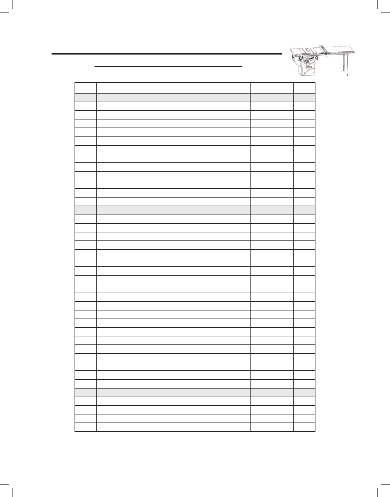
52” Fence System Rails and Extension Table
Parts List for a Cabinet Saw
No. Description Part No. Qty.
Professional Series II 52” T-Glide Fence Rails (items 1-12) TGP2-R52A 1
1 M8x1.25x16 Countersunk Socket Head Bolt TGP2-021 8
2 M8x1.25x25 Countersunk Socket Head Bolt TGP2-022 4
3 M8x23x2 Washer TGP2-023 4
4 M8 Lock Washer TGP2-024 13
5 M8x1.25 Hex Nut TGP2-025 4
6 M8x1.25x16 Hex Head Bolt TGP2-026 9
7 52” Front Rail TGP2-057 1
8 52” Rear Rail TGP2-058 1
9 52” Main Tube TGP2-059 1
10 Main Tube Endcap TGP2-030 2
11 12” Ruler TGP2-031 1
12 52” Ruler TGP2-060 1
Professional Series II 52” T-Glide Extension Table
(items 13-32) TGP2-T52A 1
13 Adjustment bracket TGP2-033 1
14 M6x1.0x18 Socket Cap Screw TGP2-034 2
15 M6 Lock Washer TGP2-035 2
16 M8x1.25x20 Countersunk Socket Head Bolt TGP2-036 2
17 M8x23x2 Washer TGP2-037 8
18 M8 Lock Washer TGP2-038 8
19 M8x1.25 Hex Nut TGP2-039 10
20 M8x1.25x35 Countersunk Socket Head Bolt TGP2-040 4
21 Foot TGP2-041 2
22 M8x1.25x65 Countersunk Socket Head Bolt TGP2-042 2
23 M10x1.5x40 Hex Head Bolt TGP2-043 2
24 M10x25x1.5 Washer TGP2-044 4
25 M10x1.5 Lock Nut TGP2-045 2
26 52” Table TGP2-061 1
27 Leg Support Bracket TGP2-047 2
28 Support Leg TGP2-048 2
29 Adjustment Screw TGP2-049 1
30 M9x18.3x2.3 Washer TGP2-050 1
31 M9 Wave Washer TGP2-051 1
32 M8 Retaining Ring TGP2-052 1
Accessories
N/A T-Glide Rails Hardware Pack TGP2-053 1
N/A T-Glide Table Hardware Pack TGP2-054 1
N/A Professional Cabinet Saw Fence System Installation Poster TGP2-055 1
N/A T-Glide Fence System Professional Series II Owner’s Manual TGP2-056 1
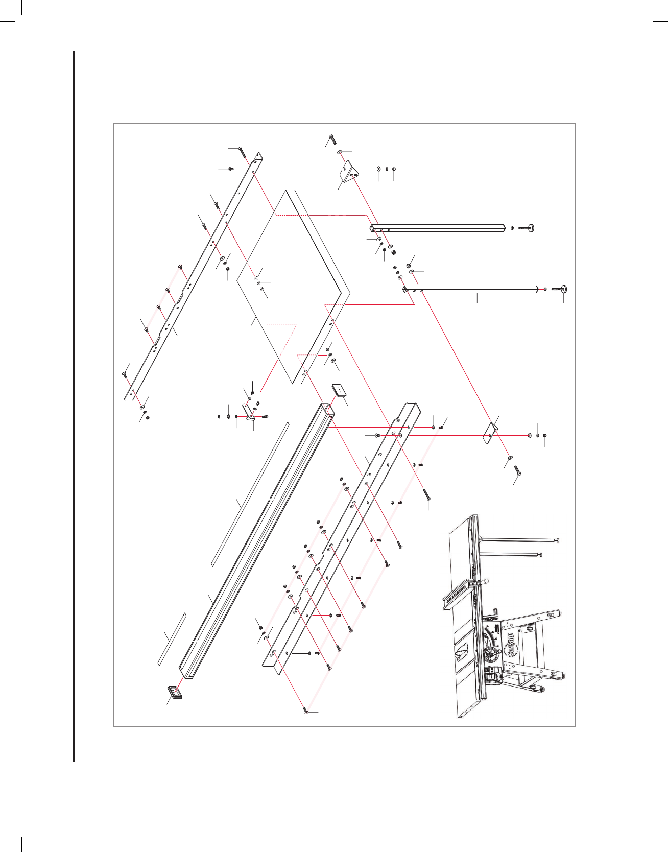
Fig. 46
Page 32 | SawStop T-Glide Fence System - Professional Series II
3
5
4
3
5
4
2
1
2
20
22
16
17
17
18
18
19
26
8
27
7
17
18
19
19
13
29
31
30
32
23
23
14
24
24
15
25
24
28
21
19
10
19
27
17
18
20
22
16
2
9
11
12
18
17
19
3
4
5
10
6
4
36” Fence System Rails and Extension Table Exploded View for a Contractor Saw

Page 33 | SawStop T-Glide Fence System - Professional Series II
No. Description Part No. Qty.
Professional Series II 36” T-Glide Fence Rails (items 1-12) TGP2-R36A 1
1 M8x1.25x16 Countersunk Socket Head Bolt TGP2-021 4
2 M8x1.25x25 Countersunk Socket Head Bolt TGP2-022 8
3 M8x23x2 Washer TGP2-023 8
4 M8 Lock Washer TGP2-024 15
5 M8x1.25 Hex Nut TGP2-025 8
6 M8x1.25x16 Hex Head Bolt TGP2-026 7
7 36” Front Rail TGP2-027 1
8 36” Rear Rail TGP2-028 1
9 36” Main Tube TGP2-029 1
10 Main Tube Endcap TGP2-030 2
11 12” Ruler TGP2-031 1
12 36” Ruler TGP2-032 1
Professional Series II 36” T-Glide Extension Table
(items 13-32) TGP2-T36A 1
13 Adjustment bracket TGP2-033 1
14 M6x1.0x18 Socket Cap Screw TGP2-034 2
15 M6 Lock Washer TGP2-035 2
16 M8x1.25x20 Countersunk Socket Head Bolt TGP2-036 2
17 M8x23x2 Washer TGP2-037 6
18 M8 Lock Washer TGP2-038 6
19 M8x1.25 Hex Nut TGP2-039 8
20 M8x1.25x35 Countersunk Socket Head Bolt TGP2-040 2
21 Foot TGP2-041 2
22 M8x1.25x65 Countersunk Socket Head Bolt TGP2-042 2
23 M10x1.5x40 Hex Head Bolt TGP2-043 2
24 M10x25x1.5 Washer TGP2-044 4
25 M10x1.5 Lock Nut TGP2-045 2
26 36” Table TGP2-046 1
27 Leg Support Bracket TGP2-047 2
28 Support Leg TGP2-048 2
29 Adjustment Screw TGP2-049 1
30 M9x18.3x2.3 Washer TGP2-050 1
31 M9 Wave Washer TGP2-051 1
32 M8 Retaining Ring TGP2-052 1
Accessories
N/A T-Glide Rails Hardware Pack TGP2-053 1
N/A T-Glide Table Hardware Pack TGP2-054 1
N/A Contractor Saw Fence System Installation Poster TGP2-062 1
N/A T-Glide Fence System Professional Series II Owner’s Manual TGP2-056 1
36” Fence System Rails and Extension Table
Parts List for a Contractor Saw

27
23
23
24
24
17
18
19
22
7
10
16
17
18
19
17
18
19
20
20
2
11
12
9
13
29
31
30
32
26
14
15
25
24
19
27
17
18
19
17
18
8
22
16
2
20
20
2
1
28
21
19
3
4
5
18
19
17
18
19
17
3
5
4
3
5
4
6
4
10
52” Fence System Rails and Extension Table Exploded View for a Contractor Saw
Fig. 47
Page 34 | SawStop T-Glide Fence System - Professional Series II

Page 35 | SawStop T-Glide Fence System - Professional Series II
No. Description Part No. Qty.
Professional Series II 52” T-Glide Fence Rails (items 1-12) TGP2-R52A 1
1 M8x1.25x16 Countersunk Socket Head Bolt TGP2-021 4
2 M8x1.25x25 Countersunk Socket Head Bolt TGP2-022 8
3 M8x23x2 Washer TGP2-023 8
4 M8 Lock Washer TGP2-024 17
5 M8x1.25 Hex Nut TGP2-025 8
6 M8x1.25x16 Hex Head Bolt TGP2-026 9
7 52” Front Rail TGP2-057 1
8 52” Rear Rail TGP2-058 1
9 52” Main Tube TGP2-059 1
10 Main Tube Endcap TGP2-030 2
11 12” Ruler TGP2-031 1
12 52” Ruler TGP2-060 1
Professional Series II 52” T-Glide Extension Table
(items 13-32) TGP2-T52A 1
13 Adjustment bracket TGP2-033 1
14 M6x1.0x18 Socket Cap Screw TGP2-034 2
15 M6 Lock Washer TGP2-035 2
16 M8x1.25x20 Countersunk Socket Head Bolt TGP2-036 2
17 M8x23x2 Washer TGP2-037 8
18 M8 Lock Washer TGP2-038 8
19 M8x1.25 Hex Nut TGP2-039 10
20 M8x1.25x35 Countersunk Socket Head Bolt TGP2-040 4
21 Foot TGP2-041 2
22 M8x1.25x65 Countersunk Socket Head Bolt TGP2-042 2
23 M10x1.5x40 Hex Head Bolt TGP2-043 2
24 M10x25x1.5 Washer TGP2-044 4
25 M10x1.5 Lock Nut TGP2-045 2
26 52” Table TGP2-061 1
27 Leg Support Bracket TGP2-047 2
28 Support Leg TGP2-048 2
29 Adjustment Screw TGP2-049 1
30 M9x18.3x2.3 Washer TGP2-050 1
31 M9 Wave Washer TGP2-051 1
32 M8 Retaining Ring TGP2-052 1
Accessories
N/A T-Glide Rails Hardware Pack TGP2-053 1
N/A T-Glide Table Hardware Pack TGP2-054 1
N/A Contractor Saw Fence System Installation Poster TGP2-062 1
N/A T-Glide Fence System Professional Series II Owner’s Manual TGP2-056 1
52” Fence System Rails and Extension Table
Parts List for a Contractor Saw

SawStop, LLC
11555 S.W. Myslony Street
Tualatin, Oregon 97062
www.sawstop.com
Main Phone - (503) 570-3200
Service - (503) 582-9934
Fax - (503) 570-3303
Email: [email protected]
January 2020
M PCS 18 0010 00
Patents Pending. Copyright SawStop, LLC. All Rights Reserved.
SawStop is a registered trademark and T-Glide is a trademark of SawStop, LLC.
Updates of this manual may be available at www.sawstop.com.
