
Page 1 of 22 LP0320
R&G
Unit
1, Shelley’s Lane, East Worldham, Alton, Hampshire, GU34 3AQ
Tel: +44 (0)
1420 89007 Fax: +44 (0)1420 87301 www.rg-racing.com Email: info@rg-racing.com
FITTING INSTRUCTIONS FOR LP0320 LICENCE PLATE BRACKET
TRIUMPH SPEED TRIPLE 1200 RS 2021-
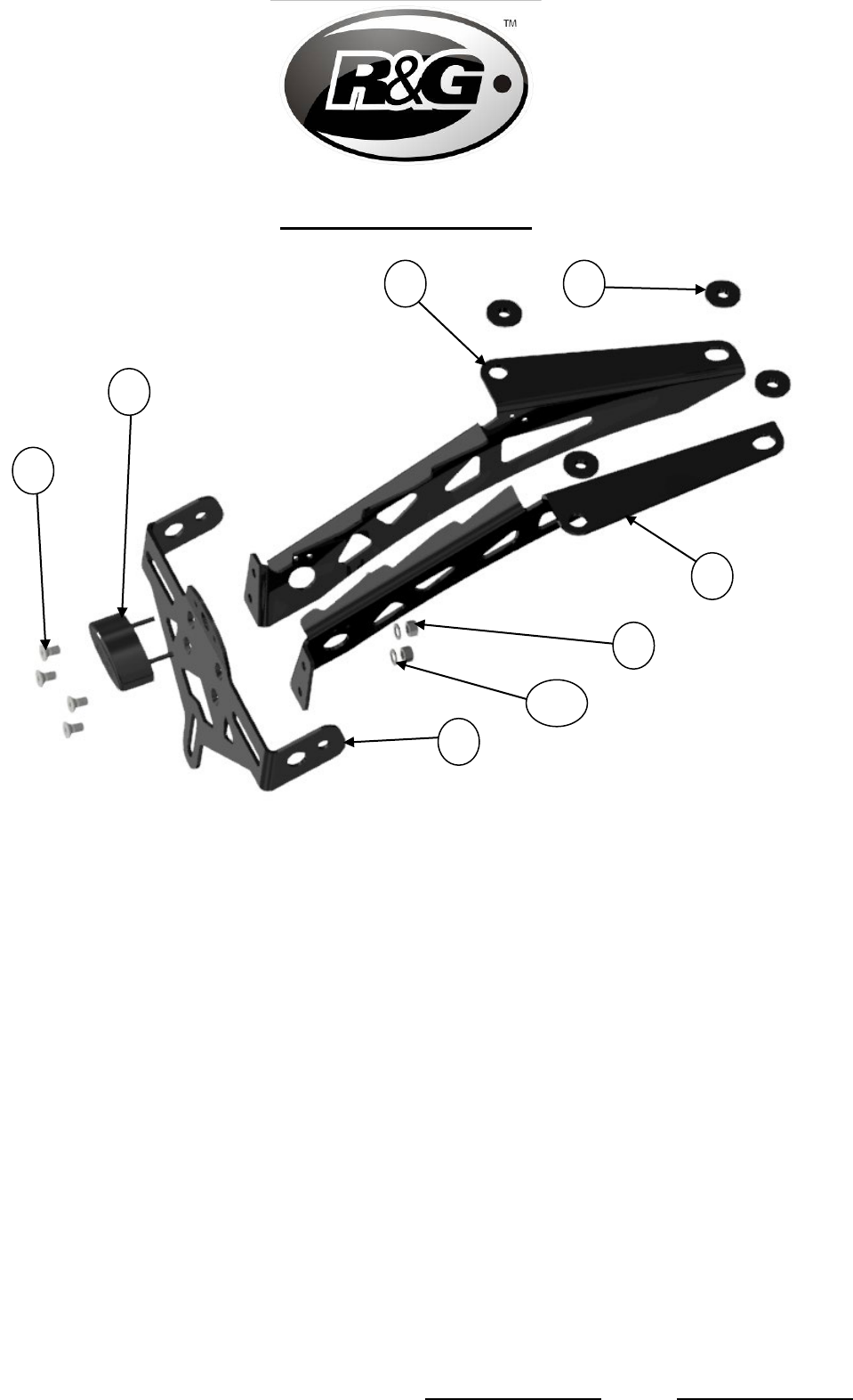
This kit contains the items pictured and labelled over page.
Some parts may be shown for clarity of instructions only.
Do not proceed until you are sure all parts are present.
Please read all instructions before proceeding.
IF IN ANY DOUBT WHEN FITTING OUR PRODUCTS, CONSULT ONE OF OUR DEALERS
OR HAVE FITTED BY A QUALIFIED TECHNICIAN.
Please note that the way the kit is packed does not necessarily represent the way of
mounting to the bike.
In the event of rubber washers being used to hold components onto bolts,
these rubber washers can be thrown away.
DIGITAL COPIES OF THESE INSTRUCTIONS ARE AVAILABLE FROM
WWW.RG-RACING.COM
Page 2 of 22 LP0320
R&G
Unit
1, Shelley’s Lane, East Worldham, Alton, Hampshire, GU34 3AQ
Tel: +44 (0)
1420 89007 Fax: +44 (0)1420 87301 www.rg-racing.com Email: info@rg-racing.com
LEGEND
ITEM No.
DESCRIPTION
QTY
ITEM 1
TB0320BK PART 1 – MAIN BRACKET RHS
1
ITEM 2
TB0320BK PART 2 – MAIN BRACKET LHS
1
ITEM 3
TB0320BK PART 3 – LICENSE PLATE BRACKET
1
ITEM 4
S1360 – MOUNTING SPACERS
4
ITEM 5
CON0065 - LICENCE PLATE ILLUMINATOR CONNECTOR
1
ITEM 6
CON0046 - INDICATOR CONNECTOR
2
ITEM 7
LA0002 - NUMBER PLATE LIGHT ASSEMBLY
1
ITEM 8
M5x0.8x10.0 mm COUNTER SUNK SCREWS
4
ITEM 9
M5x0.8 NYLOC NUTS
4
ITEM 10
M5x10mm WASHERS
4
ITEM 11
REFL 3 - REFLECTOR
1
ITEM 12
150mm LENGTH OF HEATSHRINK
3
ITEM 13
2.5mm CABLE TIES
6
ITEM 14
IWC0002 - MINI INDICATOR WIRING COVERS
2
ITEM 15
CLIP 1 – SELF ADHEISIVE CABLE CLIPS
2
ITEM 16
M6 NYLOC NUTS
2
ITEM 17
M6x1.0x15mm BUTTON HEAD SCREWS
2
ITEM 18
M6x19mm WASHERS
6
TOOLS REQUIRED
• Set of Torx keys or bits including
T20, T25, T30.
• Set of metric Allen keys to include
3, 4, 5 & 6mm
• 6 & 8mm spanner or socket.
• Phillips screwdriver.
• Small flat head screwdriver.
GENERAL TORQUE SETTINGS
M4 BOLT = 8Nm
M5 BOLT = 12Nm
M6 BOLT = 15Nm
M8 BOLT = 20Nm
M10 BOLT = 40Nm
M12 BOLT = 40Nm

Page 6 of 22 LP0320
R&G
Unit
1, Shelley’s Lane, East Worldham, Alton, Hampshire, GU34 3AQ
Tel: +44 (0)
1420 89007 Fax: +44 (0)1420 87301 www.rg-racing.com Email: info@rg-racing.com
Picture 11
Picture 12
Picture 13
Picture 14
FITTING INSTRUCTIONS
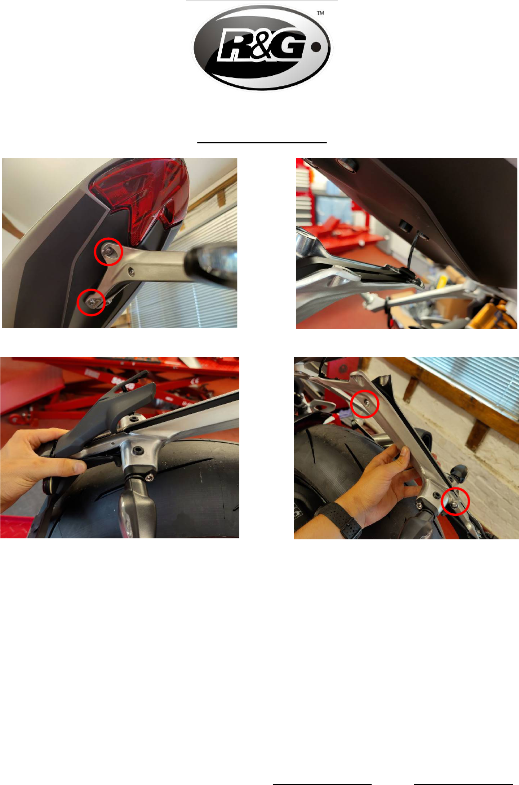
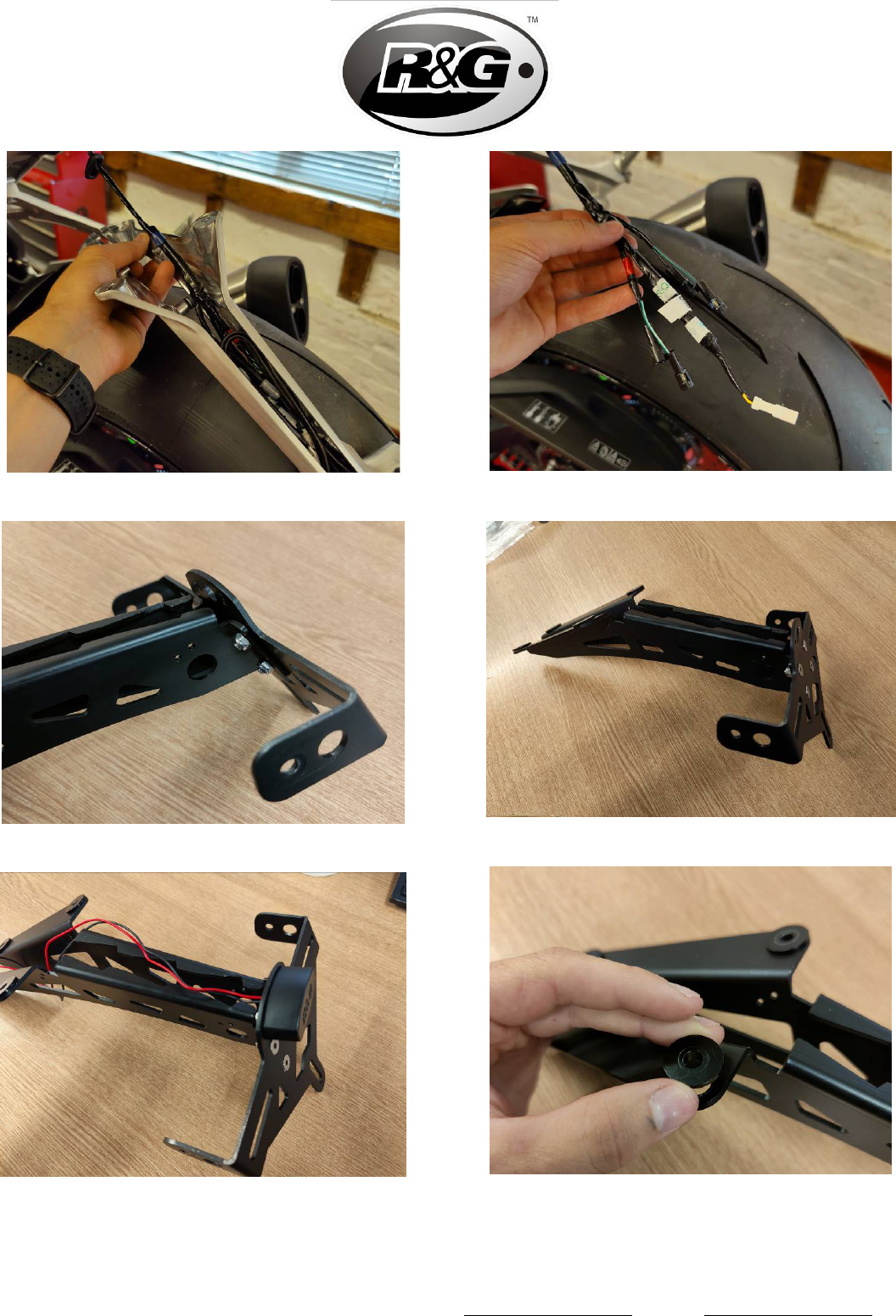
• Begin by unscrewing the bolts securing the OEM license plate holder to the tail unit of the bike
with a T20 Torx driver as shown in Picture 1.
• This will leave the license plate holder loose and connected only by the indicator wires, keep the
license plate holder supported so that the wires are not damaged.
• Gently pull the plastic cover piece to remove it as shown in Picture 3.
• This will expose the 2 screws shown in Picture 4. These must be removed using a T20 Torx
drive to sperate the 2 halves of the license plate holder.
• The remaining plastic covers can now be carefully removed.
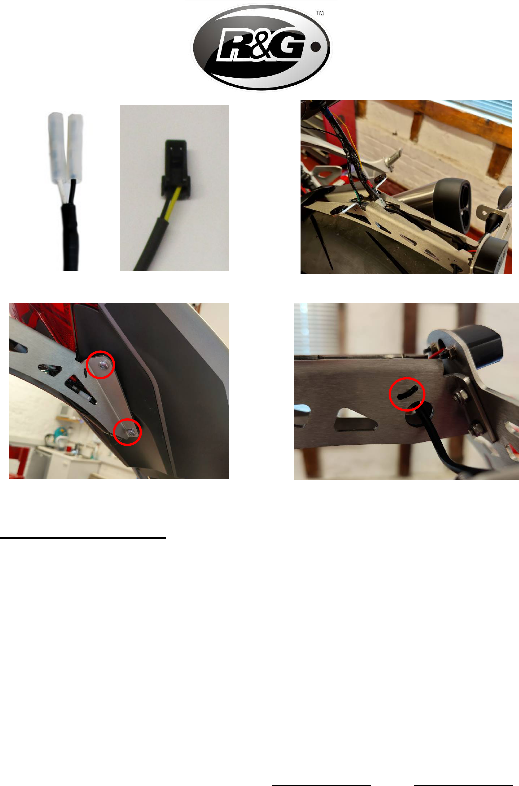
• With the indicator and illuminator connectors exposed as shown in Picture 5, disconnect these,
and remove the OEM license plate holder, leaving the wires shown in Picture 6. (Take note of
which indicators are connected to the left and right sides as these will need to be reconnected
correctly when re-connecting the R&G tail tidy.)
• If using the OEM indicators, remove the bolts holding these to the license plate holder and
unthread the wires to free them. These can then be secured to the R&G Tail Tidy using the M6
screws and nyloc nuts provided.

Page 7 of 22 LP0320
R&G
Unit
1, Shelley’s Lane, East Worldham, Alton, Hampshire, GU34 3AQ
Tel: +44 (0)
1420 89007 Fax: +44 (0)1420 87301 www.rg-racing.com Email: info@rg-racing.com
• Assemble the R&G tail tidy as shown in Picture 7 and Picture 8 using the M5 fasteners
provided.
• Attach the R&G license plate illuminator (Item 7) as shown in Picture 9.
• Insert the spacers (Item 4) into the mounting holes as shown in Picture 10 ensuring that the
flat sides face upwards.
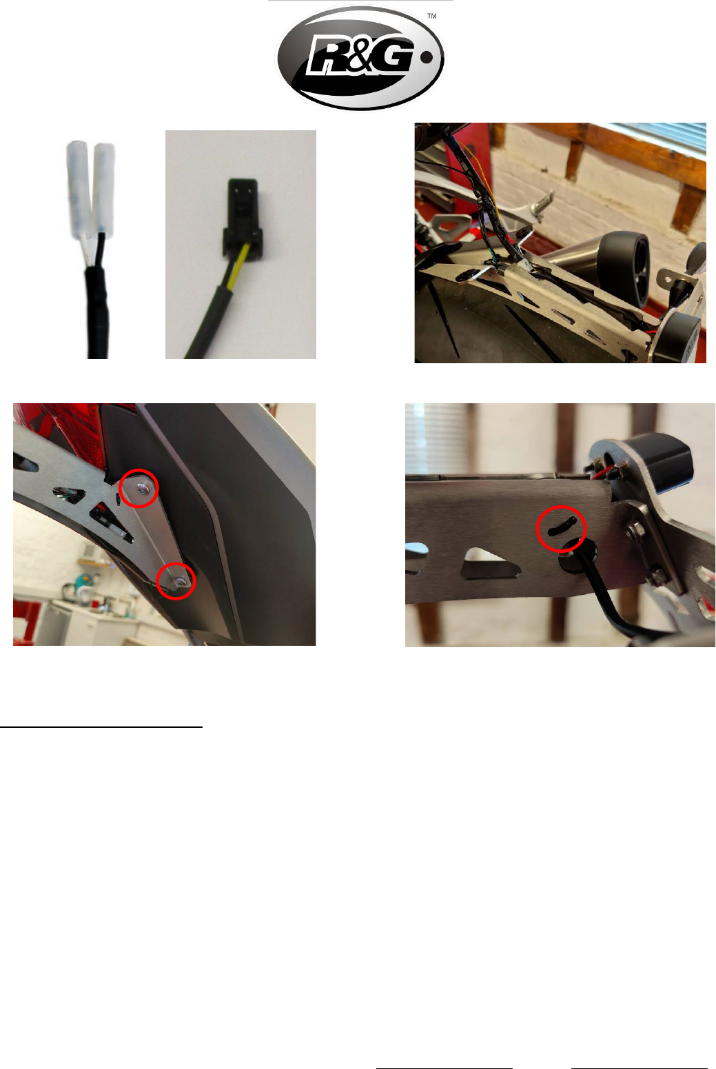
• Connect CON0065 License plate illuminator connector (Item 5) as shown on the RHS of
Picture 11, to the illuminator wires.
• If using R&G or aftermarket indicators, connect CON0046 Indicator connector (Item 6) to the
indicator wires as shown in LHS of Picture 11.
• Reconnect the indicator and illuminator connectors to the wires protruding from the tail unit of
the motorcycle. Ensure that the left and right indicators are connected correctly. (This can be
checked by turning on the ignition and testing that they flash correctly.)
• Attach the R&G tail tidy to the tail unit of the motorcycle using the same 4 Torx screws which
were removed from the OEM license plate holder as well as the M6 washers provided as shown
in Picture 13.
• The wires can be tidied up using the cable ties and cable tie slots in the tail tidy as shown in
Picture 14.
IMPORTANT: IF FITTING A FULL-SIZE LICENCE PLATE AND PLACING IT FAR DOWN ON
THE LICENCE PLATE HANGER, THERE IS A SMALL CHANCE OF THE LICENCE PLATE
HITTING THE BACK WHEEL UNDER HEAVY LOAD AND OVER LARGE BUMPS IN THE
ROAD. IT IS YOUR RESPONSIBILITY TO CHECK FOR THIS POSSIBILITY AND TAKE
AVOIDING ACTION. FAILURE TO CHECK THIS COULD RESULT IN SERIOUS INJURY.
ISSUE 1 - 30/07/2021 - (WW)
CONSUMER NOTICE
The catalogue description and any exhibition of samples are only broad indications of the Products and R&G may
make design changes which do not diminish their performance or visual appeal and supplying them in such state
shall conform to the order. The Buyer acknowledges no representation or warranty (other than as to title) has
been given or will apply to the Products other than those in R&G’s order or confirmation and the Buyer confirms it
has chosen the Products as being of merchantable quality and suitable for its particular purposes. Where R&G fits
the Products or undertakes other services it shall exercise reasonable skill and care and rectify any fault free of
charge unless the workmanship has been disturbed. The Buyer is responsible for ensuring that the warranty on
the motorcycle is not affected by the fitting of the Products. On return of any defective Products R&G shall at its
option either supply a replacement or refund the purchase money but shall not be liable if the Products have been
modified or used or maintained otherwise than in accordance with R&G’s or manufacturer’s instructions and good
engineering practice or if the defect arises from accident or neglect. Other than identified above and subject to
R&G not limiting its liability for causing death and personal injury, it shall not be liable for indirect or consequential
loss and otherwise its liability shall be limited to the amounts paid by the Buyer for the Products or the fitting or
service concerned. These terms do not affect the Buyer’s statutory rights.
R&G RACING RETURNS POLICY (NON-FAULTY GOODS)
Returns must be pre-authorised (if not pre-authorised the return will be rejected). Goods may only be returned
direct to us if they were purchased direct from us (customer must prove if necessary). Otherwise to be returned
to original vendor. Goods must be in re-sellable condition, in the opinion of R&G Racing. All returns are subject to
a 25% restocking and handling fee (25% of the gross value exc. P&P – at the prevailing price at time of
purchase). The customer must pay any and all carriage charges. No returns of discontinued products, unless
within 14 days of purchase. This policy does not affect your statutory rights and does not refer to faulty goods.

Page 8 of 22 LP0320
R&G
Unit
1, Shelley’s Lane, East Worldham, Alton, Hampshire, GU34 3AQ
Tel: +44 (0)
1420 89007 Fax: +44 (0)1420 87301 www.rg-racing.com Email: info@rg-racing.com
NOTICE DE MONTAGE POUR LP0320 SUPPORT DE PLAQUE
TRIUMPH SPEED TRIPLE 1200 RS 2021-
C
E KIT CONTIENT LES ARTICLES ILLUSTRES ET ETIQUETES SUR LA PAGE
.
CERTAINES PARTIES PEUVENT ETRE PRESENTES UNIQUEMENT POUR LA CLARTE DES INSTRUCTIONS.
N
E PAS PROCEDER AU MONTAGE TANT QUE VOUS N'ETES PAS SUR QUE TOUTES LES PIECES SOIENT
PRESENTES
.
V
EUILLEZ LIRE TOUTES LES INSTRUCTIONS AVANT DE CONTINUER.
EN CAS DE DOUTE LORS DU MONTAGE DE NOS PRODUITS, CONSULTEZ UN DE NOS
REVENDEURS OU FAITES APPEL A UN TECHNICIEN QUALIFIÉ.
VEUILLEZ NOTER QUE LA FAÇON DONT LE KIT EST EMBALLE NE REPRESENTE PAS NECESSAIREMENT LA
MANIERE DE LE MONTER SUR LA MOTO
.
SI DES RONDELLES EN CAOUTCHOUC SONT UTILISEES POUR MAINTENIR LES COMPOSANTS SUR LES
BOULONS
, ELLES PEUVENT ETRE JETEES.
NOTICE DISPONIBLE AU TELECHARGEMENT SUR :
WWW.RG-RACING.COM

Page 9 of 22 LP0320
R&G
Unit
1, Shelley’s Lane, East Worldham, Alton, Hampshire, GU34 3AQ
Tel: +44 (0)
1420 89007 Fax: +44 (0)1420 87301 www.rg-racing.com Email: info@rg-racing.com
LÉGENDE
ARTICLE No.
DESCRIPTION
QTÉ
ARTICLE 1
TB0320BK PARTIE 1 – SUPPORT PRINCIPAL CÔTÉ DROIT
1
ARTICLE 2
TB0320BK PARTIE 2 – SUPPORT PRINCIPAL CÔTÉ GAUCHE
1
ARTICLE 3
TB0320BK PARTIE 3 – SUPPORT DE PLAQUE
1
ARTICLE 4
S1360 – ENTRETOISES DE MONTAGE
4
ARTICLE 5
CON0065 – CONNECTEUR DE FEU DE PLAQUE
1
ARTICLE 6
CON0046 – CONNECTEUR DE CLIGNOTANT
2
ARTICLE 7
LA0002 – ASSEMBLAGE DE FEU DE PLAQUE
1
ARTICLE 8
M5x0.8x10.0 mm VIS
4
ARTICLE 9
M5x0.8 ÉCROUS
4
ARTICLE 10
M5x10mm RONDELLES
4
ARTICLE 11
REFL 3 – RÉFLECTEUR
1
ARTICLE 12
150mm MANCHON THERMO RÉTRACTABLE
3
ARTICLE 13
2.5mm COLLIERS DE SERRAGE
6
ARTICLE 14
IWC0002 – CACHES FILS DE MINI CLIGNOTANT
2
ARTICLE 15
CLIP 1 – CLIPS CÂBLE AUTOCOLLANT
2
ARTICLE 16
M6 ÉCROUS
2
ARTICLE 17
M6x1.0x15mm VIS
2
ARTICLE 18
M6x19mm RONDELLES
6
OUTILS REQUIS
• Clés Torx T20, T25, T30.
• Clés Allen 3, 4, 5 & 6mm
• Clé à cliquet + douille 6 & 8mm.
• Tournevis cruciforme.
• Petit tournevis plat.
VALEURS DE SERRAGE
M4 BOULON = 8Nm
M5 BOULON = 12Nm
M6 BOULON = 15Nm
M8 BOULON = 20Nm
M10 BOULON = 40Nm
M12 BOULON = 40Nm


Page 13 of 22 LP0320
R&G
Unit
1, Shelley’s Lane, East Worldham, Alton, Hampshire, GU34 3AQ
Tel: +44 (0)
1420 89007 Fax: +44 (0)1420 87301 www.rg-racing.com Email: info@rg-racing.com
Photo 11
Photo 12
Photo 13
Photo 14
NOTICE DE MONTAGE
• Commencez par dévisser les boulons fixant le support de plaque d'immatriculation d’origine à
l'empennage de la moto avec un tournevis Torx T20, comme indiqué sur la photo 1.
• Cela laissera le support de plaque d'immatriculation lâche et connecté uniquement par les fils de
clignotants, maintenez le support de plaque d'immatriculation afin que les fils ne soient pas
endommagés.
• Tirez doucement sur le couvercle en plastique pour le retirer comme indiqué sur la photo 3.
• Cela exposera les 2 vis illustrées sur la photo 4. Celles-ci doivent être retirées à l'aide d'une clé
Torx T20 pour séparer les 2 moitiés du support de plaque d'immatriculation.
• Les couvercles en plastique restants peuvent maintenant être retirés avec précaution.
• Une fois les connecteurs de clignotant et de feu exposés comme indiqué sur la photo 5,
déconnectez-les et retirez le support de plaque d'immatriculation d’origine, en laissant les fils
illustrés sur la photo 6. (Notez quels clignotants sont connectés aux côtés gauche et droit car ils
doivent être reconnectés correctement lors de la reconnexion du support R&G).

Page 14 of 22 LP0320
R&G
Unit
1, Shelley’s Lane, East Worldham, Alton, Hampshire, GU34 3AQ
Tel: +44 (0)
1420 89007 Fax: +44 (0)1420 87301 www.rg-racing.com Email: info@rg-racing.com
• Si vous utilisez les clignotants d’origine, retirez les boulons qui les maintiennent au support de
plaque d'immatriculation et dévissez les fils pour les libérer. Ceux-ci peuvent ensuite être fixés
au support R&G à l'aide des vis M6 et des écrous nyloc fournis.
• Assemblez le support de plaque R&G comme indiqué sur la photo 7 et la photo 8 à l'aide des
attaches M5 fournies.
• Fixez le feu de plaque d'immatriculation R&G (Article 7) comme indiqué sur la Photo 9.
• Insérez les entretoises (Article 4) dans les trous de montage comme indiqué sur la Photo 10 en
veillant à ce que les côtés plats soient orientés vers le haut.
• Connectez le connecteur du feu de plaque d'immatriculation CON0065 (Article 5) comme
indiqué sur le côté droit de la Photo 11, aux fils de l'éclairage.
• Si vous utilisez des clignotants R&G ou de rechange, connectez le connecteur de clignotant
CON0046 (article 6) aux fils de clignotant comme indiqué sur la gauche de la photo 11.
• Rebranchez les connecteurs de clignotant et de feu aux fils dépassant de l'unité arrière de la
moto. Assurez-vous que les clignotants gauche et droit soient correctement connectés. (Cela
peut être vérifié en mettant le contact et en vérifiant qu'ils clignotent correctement).
• Fixez le support R&G à l'unité de la moto en utilisant les mêmes 4 vis Torx qui ont été retirées
du support de plaque d'immatriculation d’origine ainsi que les rondelles M6 fournies comme
indiqué sur la photo 13.
• Les fils peuvent être rangés à l'aide des serre-câbles et des fentes pour serre-câbles dans le
support arrière, comme indiqué sur la photo 14.
IMPORTANT: SI VOUS INSTALLEZ UNE PLAQUE D'IMMATRICULATION DE GRANDE
TAILLE ET LA PLACEZ LOIN VERS LE BAS SUR LE SUPPORT DE PLAQUE
D'IMMATRICULATION, IL Y A UNE FAIBLE CHANCE QUE LA PLAQUE
D'IMMATRICULATION FRAPPE LA ROUE ARRIÈRE SOUS L’EFFET D’UNE CHARGE
LOURDE ET SUR DE GRANDES BOSSES SUR LA ROUTE. IL EST DE VOTRE
RESPONSABILITÉ DE VÉRIFIER CETTE POSSIBILITÉ ET DE PRENDRE DES MESURES
POUR L'ÉVITER. NE PAS VÉRIFIER CECI POURRAIT ENTRAÎNER DES BLESSURES
GRAVES.
ISSUE 1 - 30/07/2021 - (WW)
CONSUMER NOTICE
The catalogue description and any exhibition of samples are only broad indications of the Products and R&G may
make design changes which do not diminish their performance or visual appeal and supplying them in such state
shall conform to the order. The Buyer acknowledges no representation or warranty (other than as to title) has
been given or will apply to the Products other than those in R&G’s order or confirmation and the Buyer confirms it
has chosen the Products as being of merchantable quality and suitable for its particular purposes. Where R&G fits
the Products or undertakes other services it shall exercise reasonable skill and care and rectify any fault free of
charge unless the workmanship has been disturbed. The Buyer is responsible for ensuring that the warranty on
the motorcycle is not affected by the fitting of the Products. On return of any defective Products R&G shall at its
option either supply a replacement or refund the purchase money but shall not be liable if the Products have been
modified or used or maintained otherwise than in accordance with R&G’s or manufacturer’s instructions and good
engineering practice or if the defect arises from accident or neglect. Other than identified above and subject to
R&G not limiting its liability for causing death and personal injury, it shall not be liable for indirect or consequential
loss and otherwise its liability shall be limited to the amounts paid by the Buyer for the Products or the fitting or
service concerned. These terms do not affect the Buyer’s statutory rights.
R&G RACING RETURNS POLICY (NON-FAULTY GOODS)
Returns must be pre-authorised (if not pre-authorised the return will be rejected). Goods may only be returned
direct to us if they were purchased direct from us (customer must prove if necessary). Otherwise to be returned
to original vendor. Goods must be in re-sellable condition, in the opinion of R&G Racing. All returns are subject to

Page 15 of 22 LP0320
R&G
Unit
1, Shelley’s Lane, East Worldham, Alton, Hampshire, GU34 3AQ
Tel: +44 (0)
1420 89007 Fax: +44 (0)1420 87301 www.rg-racing.com Email: info@rg-racing.com
a 25% restocking and handling fee (25% of the gross value exc. P&P – at the prevailing price at time of
purchase). The customer must pay any and all carriage charges. No returns of discontinued products, unless
within 14 days of purchase. This policy does not affect your statutory rights and does not refer to faulty goods.

Page 16 of 22 LP0320
R&G
Unit
1, Shelley’s Lane, East Worldham, Alton, Hampshire, GU34 3AQ
Tel: +44 (0)
1420 89007 Fax: +44 (0)1420 87301 www.rg-racing.com Email: info@rg-racing.com
MONTAGEANLEITUNG FÜR LP0320 KENNZEICHENHALTER
TRIUMPH SPEED TRIPLE 1200 RS 2021-
Alle Kit-Teile sind auf den nachfolgenden Seiten abgebildet und gekennzeichnet.
Die abgebildeten Teile dienen lediglich zur Erklärung.
Überprüfen Sie zuerst, dass alle Teile vorhanden sind.
Lesen Sie die Montageanleitung komplett durch, bevor Sie anfangen.
WENN SIE BEI DER MONTAGE DIESES PRODUKTES UNSICHER SIND, BITTE EINEN
UNSERER HÄNDLER KONTAKTIEREN ODER DAS KIT VON EINEM QUALIFIZIERTEN
ZWEIRAD-MECHANIKER MONTIEREN LASSEN.
DIE VERPACKUNG DER TEILE STELLT NICHT DIE REIHENFOLGE DER MONTAGE DAR.
HINWEIS FÜR KITS MIT PLASTIKUNTERLEGSCHEIBEN AN DEN SCHRAUBEN –
DIESE PLASTIK-UNTERLEGSCHEIBEN WERDEN NICHT FÜR DEN EINBAU BENÖTIGT
EINE DIGITALE VERSION DIESER MONTAGEANLEITUNG KANN AUF
FOLGENDER SEITE HERUNTERGELADEN WERDEN: WWW.RG-RACING.COM
Page 17 of 22 LP0320
R&G
Unit
1, Shelley’s Lane, East Worldham, Alton, Hampshire, GU34 3AQ
Tel: +44 (0)
1420 89007 Fax: +44 (0)1420 87301 www.rg-racing.com Email: info@rg-racing.com
LIEFERUMFANG
ARTIKEL NR.
BESCHREIBUNG
MENGE
ARTIKEL 1
TB0320BK TEIL 1 – HAUPTHALTERUNG RECHTE SEITE
1
ARTIKEL 2
TB0320BK TEIL 2 – HAUPTHALTERUNG LINKE SEITE
1
ARTIKEL 3
TB0320BK TEIL 3 – KENNZEICHENHALTER
1
ARTIKEL 4
S1360 – MONTAGE-DISTANZHALTER
4
ARTIKEL 5
CON0065 – VERBINDUNG KENNZEICHENBELEUCHTUNG
1
ARTIKEL 6
CON0046 - BLINKERVERBINDUNG
2
ARTIKEL 7
LA0002 – KENNZEICHENBELEUCHTUNGSEINHEIT
1
ARTIKEL 8
M5x0.8x10.0 mm SENKSCHRAUBE
4
ARTIKEL 9
M5x0.8 SELBSTSICHERNDE MUTTER
4
ARTIKEL 10
M5x10mm UNTERLEGSCHEIBE
4
ARTIKEL 11
REFL 3 - RÜCKSTAHLER
1
ARTIKEL 12
150mm SCHRUMPFSCHLAUCH
3
ARTIKEL 13
2.5mm KABELBINDER
6
ARTIKEL 14
IWC0002 – MINIBLINKER KABEL-ABDECKUNG
2
ARTIKEL 15
CLIP 1 – SELBSTSICHERNDE KABELCLIP
2
ARTIKEL 16
M6 SELBSTSICHERNDE MUTTER
2
ARTIKEL 17
M6x1.0x15mm INBUSSCHRAUBE
2
ARTIKEL 18
M6x19mm UNTERLEGSCHEIBE
6
SIE BENÖTIGEN FOLGENDES WERKZEUG
• Satz Torx-Schlüssel inkl. T20,
T25, T30.
• Satz Inbusschlüssel inkl. 3, 4, 5 &
6mm
• 6 & 8mm Schraubenschlüssel oder
Steckschlüssel
• Kreuzschlitz-Schraubendreher
• Flachklingen-Schraubendreher
ALLGEM. ANZUGSDREHMOMENT
M4 SCHRAUBE = 8Nm
M5 SCHRAUBE = 12Nm
M6 SCHRAUBE = 15Nm
M8 SCHRAUBE = 20Nm
M10 SCHRAUBE = 40Nm
M12 SCHRAUBE = 40Nm


Page 21 of 22 LP0320
R&G
Unit 1, Shelley’s Lane, East Worldham, Alton, Hampshire, GU34 3AQ
Tel: +44 (0)1420 89007 Fax: +44 (0)1420 87301 www.rg-racing.com Email: info@rg-racing.com
Abbildung 11
Abbildung 12
Abbildung 13
Abbildung 14
MONTAGEANLEITUNG
• Fangen Sie an, indem Sie die Schrauben mit einem T20 Torx-Schlüssel lösen, die den original
Kennzeichenhalter am Heck befestigen wie in Abbildung 1 abgebildet.
• Der Kennzeichenhalter sitzt nun locker und ist nur durch die Kabel für die Blinker verbunden.
Stützen Sie daher den Kennzeichenhalter, sodass die Kabel nicht beschädigt werden.
• Das Verkleidungsteil aus Kunststoff hochziehen, um es zu entfernen wie in Abbildung 3
abgebildet.
• Danach sehen Sie die 2 Schrauben, die in Abbildung 4 abgebildet sind. Diese müssen mit
einem T20 Torx-Schlüssel entfernt werden, um den Kennzeichenhalter in zwei Teile zu trennen.
• Die übrigen Kunststoffabdeckungen können nun vorsichtig entfernt werden.
• Nachdem die Verbindungen für die Blinker und die Kennzeichenbeleuchtung zu sehen sind
(siehe Abbildung 5), trennen Sie dies und entfernen Sie den Kennzeichenhalter. Die Kabel so
lassen wie in Abbildung 6 abgebildet. (Bitte notieren Sie wie die Blinker angeschlossen waren
– linke und rechte Seite – sodass Sie diese später am R&G Kennzeichenhalter richtig montiert
werden können.)
• Wenn Sie es vorhaben, die Originalblinker wieder zu montieren, entfernen Sie die Schrauben,
die die Blinker am Kennzeichenhalter befestigen und die Kabel ausfädeln. Diese können dann

Page 22 of 22 LP0320
R&G
Unit 1, Shelley’s Lane, East Worldham, Alton, Hampshire, GU34 3AQ
Tel: +44 (0)1420 89007 Fax: +44 (0)1420 87301 www.rg-racing.com Email: info@rg-racing.com
am R&G Kennzeichenhalter mit den M6 Schrauben und selbstsichernden Muttern vom Kit
gesichert werden.
• Den R&G Kennzeichenhalter mit den M5 Befestigungssteilen vom Kit zusammenbauen wie in
Abbildung 7 und Abbildung 8 abgebildet.
• Die Kennzeichenbeleuchtung (Artikel 7) anbringen wie in Abbildung 9 abgebildet.
• Die Distanzhalter (Artikel 4) in die Montageöffnungen einsetzen wie in Abbildung 10
abgebildet mit der flachen Fläche nach oben gerichtet.
• Verbinden Sie die CON0065 Verbindung für die Kennzeichenbeleuchtung (Artikel 5) mit den
Kabeln für die Kennzeichenbeleuchtung wie in Abbildung 11 abgebildet.
• Wenn Sie R&G Blinker oder Blinker aus dem Zubehörmarkt montieren, verbinden Sie die
CON0046 Verbindung (Artikel 6) mit den Kabeln für die Blinker wie auf der linken Seite in
Abbildung 11 abgebildet.
• Verbinden Sie die Blinker- und Beleuchtungsverbindungen wieder mit den Kabeln, die am Heck
des Motorrades hervorstehen. Stellen Sie sicher, dass die rechte und linke Blinker richtig
angeschlossen sind. (Dies können Sie überprüfen, indem Sie die Zündung einschalten und
kontrollieren, dass die Blinker entsprechend blinken.)
• Den R&G Kennzeichenhalter am Heck des Motorrades montieren – benutzen Sie dieselben 4
Torx-Schrauben, die vom original Kennzeichenhalter entfernt wurden sowie die M6
Unterlegscheiben vom Kit wie in Abbildung 13 abgebildet.
• Die Kabel mittels Kabelbinder und Schlitze für die Kabelbinder im Kennzeichenhalter ordentlich
verstauen wie in Abbildung 14 abgebildet.
WICHTIG: WENN EIN GROSSES KENNZEICHEN ZU WEIT NACH UNTEN MONTIERT
WIRD, BESTEHT BEI SCHWERER LAST ODER DURCH GROSSE BODENWELLEN EIN
GERINGES RISIKO, DASS DAS KENNZEICHEN AN DAS HINTERRAD STOSSEN KANN. ES
LIEGT IN IHRER VERANTWORTUNG DIES ZU ÜBERPRÜFEN UND, WENN NOTWENDIG,
ZU VORBEUGENDEN MASSNAHMEN ZU ERGREIFEN. DIE NICHTBEACHTUNG DIESES
SICHERHEITSHINWEISES KANN ZU SCHWEREN VERLETZUNGEN FÜHREN.
0
AUSGABE 1 - 30/07/2021 - (WW)
CONSUMER NOTICE
The catalogue description and any exhibition of samples are only broad indications of the Products and R&G may
make design changes which do not diminish their performance or visual appeal and supplying them in such state
shall conform to the order. The Buyer acknowledges no representation or warranty (other than as to title) has
been given or will apply to the Products other than those in R&G’s order or confirmation and the Buyer confirms it
has chosen the Products as being of merchantable quality and suitable for its particular purposes. Where R&G fits
the Products or undertakes other services it shall exercise reasonable skill and care and rectify any fault free of
charge unless the workmanship has been disturbed. The Buyer is responsible for ensuring that the warranty on
the motorcycle is not affected by the fitting of the Products. On return of any defective Products R&G shall at its
option either supply a replacement or refund the purchase money but shall not be liable if the Products have been
modified or used or maintained otherwise than in accordance with R&G’s or manufacturer’s instructions and good
engineering practice or if the defect arises from accident or neglect. Other than identified above and subject to
R&G not limiting its liability for causing death and personal injury, it shall not be liable for indirect or consequential
loss and otherwise its liability shall be limited to the amounts paid by the Buyer for the Products or the fitting or
service concerned. These terms do not affect the Buyer’s statutory rights.
R&G RACING RETURNS POLICY (NON-FAULTY GOODS)
Returns must be pre-authorised (if not pre-authorised the return will be rejected). Goods may only be returned
direct to us if they were purchased direct from us (customer must prove if necessary). Otherwise to be returned
to original vendor. Goods must be in re-sellable condition, in the opinion of R&G Racing. All returns are subject to
a 25% restocking and handling fee (25% of the gross value exc. P&P – at the prevailing price at time of
purchase). The customer must pay any and all carriage charges. No returns of discontinued products, unless
within 14 days of purchase. This policy does not affect your statutory rights and does not refer to faulty goods.
