
Page 1 of 21 LP0308
R&G
Unit
1, Shelley’s Lane, East Worldham, Alton, Hampshire, GU34 3AQ
Tel: +44 (0)
1420 89007 Fax: +44 (0)1420 87301 www.rg-racing.com Email: info@rg-racing.com
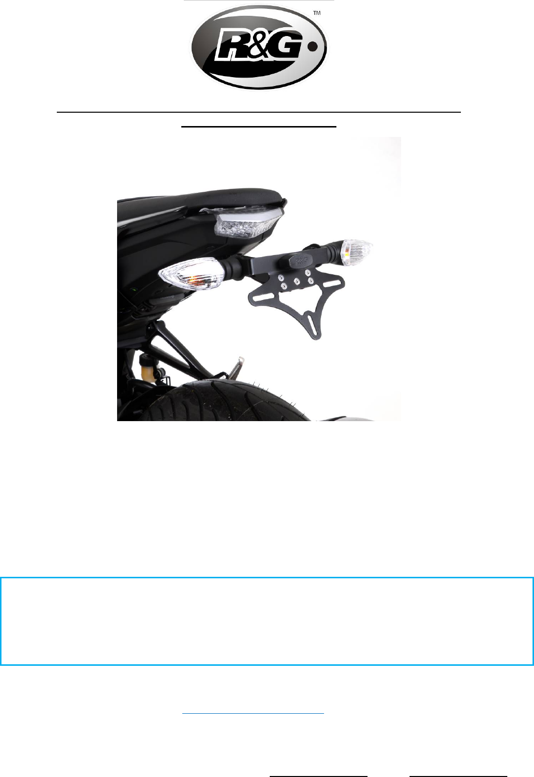
FITTING INSTRUCTIONS FOR LP0308BK LICENCE PLATE BRACKET
YAMAHA MT-125 2020-
This kit contains the items pictured and labelled over page.
Some parts may be shown for clarity of instructions only.
Do not proceed until you are sure all parts are present.
Please read all instructions before proceeding.
IF IN ANY DOUBT WHEN FITTING OUR PRODUCTS, CONSULT ONE OF OUR DEALERS
OR HAVE FITTED BY A QUALIFIED TECHNICIAN.
Please note that the way the kit is packed does not necessarily represent the way of
mounting to the bike.
In the event of rubber washers being used to hold components onto bolts,
these rubber washers can be thrown away.
DIGITAL COPIES OF THESE INSTRUCTIONS ARE AVAILABLE FROM
WWW.RG-RACING.COM

Page 2 of 21 LP0308
R&G
Unit
1, Shelley’s Lane, East Worldham, Alton, Hampshire, GU34 3AQ
Tel: +44 (0)
1420 89007 Fax: +44 (0)1420 87301 www.rg-racing.com Email: info@rg-racing.com
LEGEND
ITEM No.
DESCRIPTION
QTY
ITEM 1
TB0308 PART 1 – MAIN BRACKET
1
ITEM 2
TB0308 PART 2 - LICENCE PLATE MOUNT PLATE
1
ITEM 3
TB0308 PART 3 – COVER PLATE
1
ITEM 4
I0016 – INDICATOR ADAPTORS
4
ITEM 5
I0037 – OEM INDICATOR ADAPTORS
2
ITEM 6
RB0004 - RUBBER GROMMET
1
ITEM 7
CON0007 - LICENCE PLATE ILLUMINATOR CONNECTOR
1
ITEM 8
CON0027 - INDICATOR CONNECTOR
2
ITEM 9
LA0002 - NUMBER PLATE LIGHT ASSEMBLY
1
ITEM 10
M6x1.0x30.0mm BUTTON HEAD BOLTS
4
ITEM 11
M5x0.8x10.0 mm COUNTER SUNK SCREWS
5
ITEM 12
M5x0.8 NYLOC NUTS
5
ITEM 13
M6x12mm WASHERS
4
ITEM 14
REFL 3 - REFLECTOR
1
ITEM 15
150mm LENGTH OF HEATSHRINK
3
ITEM 16
2.5mm CABLE TIES
4
ITEM 17
IWC0002 - MINI INDICATOR WIRING COVERS
2
TOOLS REQUIRED
• Set of metric Allen keys to include
3, 4, 5 & 6mm.
• Set of metric sockets or spanners
to include 6, 8, 10 & 12mm.
• Phillips screwdriver.
• Small flat head screwdriver.
GENERAL TORQUE SETTINGS
M4 BOLT = 8Nm
M5 BOLT = 12Nm
M6 BOLT = 15Nm
M8 BOLT = 20Nm
M10 BOLT = 40Nm
M12 BOLT = 40Nm


Page 6 of 21 LP0308
R&G
Unit
1, Shelley’s Lane, East Worldham, Alton, Hampshire, GU34 3AQ
Tel: +44 (0)
1420 89007 Fax: +44 (0)1420 87301 www.rg-racing.com Email: info@rg-racing.com
FITTING INSTRUCTIONS
• To fit the R&G tail tidy, remove the seat from the bike using the key under the tail unit as
shown in Picture 1.
• Remove the 2 bolts also shown in Picture 1, using a 10mm socket or spanner.
• Remove the 4 bolts shown in Picture 2 using a 4 & 5mm Allen key.
• The tail unit right-hand-side panel can now be removed from the tail unit in order to free the
cables to the indicators and rear light.
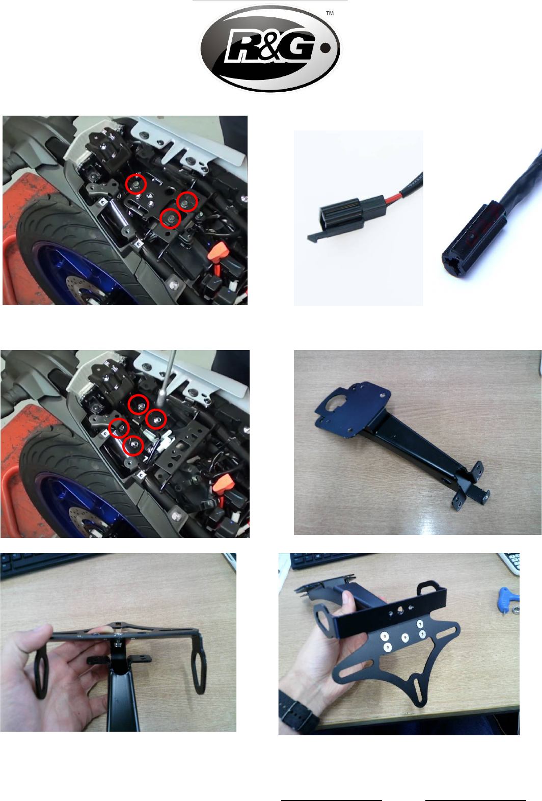
• Next, Remove the 3 bolts shown in in Picture 3, to remove the fuse bracket and seat lock
mechanism plate.
• Unplug the indicator and illuminator cables with a small screwdriver to free the connectors
shown in Picture 4.
• The 4 nuts in Picture 5 can now me removed, which frees the support bracket and bolts
holding the original license plate holder in place. Keep these 4 nuts safe as they will be re-used
on the R&G tail tidy.
• Carefully remove the cables attached to the original license plate holder through the small hole
in the underside of the tail unit.
• With the original license plate holder removed, you must first assemble the R&G tail tidy before
it can be attached.
• Secure Item 2 (License plate mount plate) to Item 3 (Cover plate) using an M5 countersunk
screw. Tighten with an M5 washer and nyloc nut.
• Next, attach Item 1 (Main bracket) to Item 2 (License plate mount plate) as shown in Picture
8, with the same M5 screws, washers and nuts shown in Picture 9.
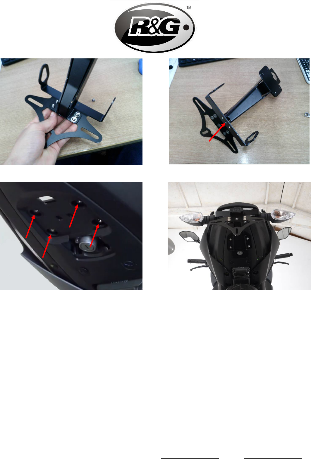
• If using the original indicators, these can be removed from the original license plate holder and
attached to the R&G tail tidy using the OEM indicator adaptors (Item 5)
• If using R&G or other indicators, Item 4 (indicator adaptors) can be used to attach these.
• Attach the License plate illuminator (Item 9) to the tail tidy through the holes shown in Picture
10.
• Attach the illuminator connector (left side of Picture 4) to the bullet connections on the R&G
illuminator wires. If using R&G or other indicators, attach the indicator connectors (right side of
Picture 4) to the bullet connections on the indicator wires.
• Route the indicator and illuminator wires through the centre of the tail tidy between the main
bracket and the cover plate until they are exposed at the main mounting area.

Page 7 of 21 LP0308
R&G
Unit
1, Shelley’s Lane, East Worldham, Alton, Hampshire, GU34 3AQ
Tel: +44 (0)
1420 89007 Fax: +44 (0)1420 87301 www.rg-racing.com Email: info@rg-racing.com
• The R&G tail tidy can now be offered up to the mounting holes on the underside of the tail unit.
At this time route the cables through the hole where they were removed previously.
• Insert the M6 bolts and secure the tail tidy in place while reattaching the support bracket shown
in Picture 5.
• Tighten the 4 M6 screws with the M6 washers and the nuts which were removed from the
original license plate holder as shown in Picture 5.
• Re-connect the illuminator and indicator wires, ensuring that the left and right sides are
connected correctly respectively.
• The fuse bracket and seat catch mechanism plates can now be re-attached using the same bolts
removed in Picture 3.
• Now the tail right-hand-side panel can be re-attached by first fastening the bolts shown in
Picture 2, and then fastening the screws shown in Picture 1.
• The seat can then be re-attached, ensuring that it positively clicks into place and is secured by
the locking mechanism.
• The Rubber bung provided (Item 6) can be used to cover the seat key lock and keep it free
from dirt and water. Push it over the lock barrel and it will stay in place. Note that the key lock
can be operated with the rubber bung in place.
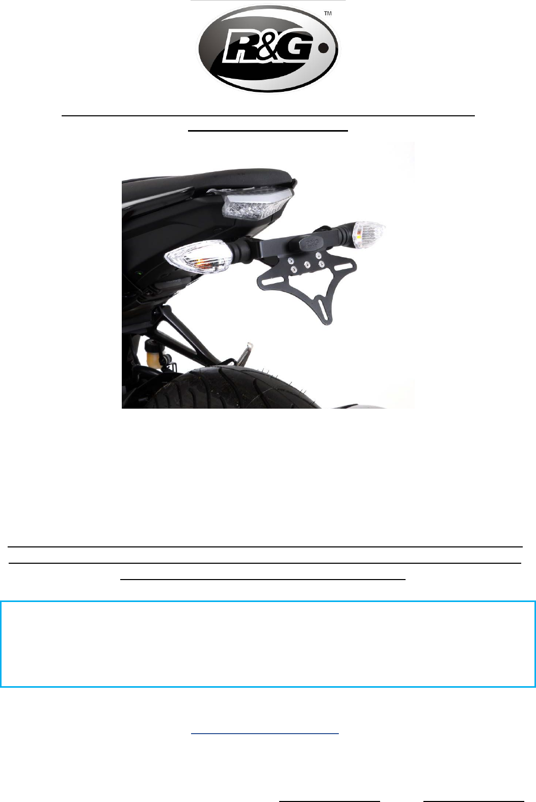
IMPORTANT: IF FITTING A FULL-SIZE LICENCE PLATE AND PLACING IT FAR DOWN ON
THE LICENCE PLATE HANGER, THERE IS A SMALL CHANCE OF THE LICENCE PLATE
HITTING THE BACK WHEEL UNDER HEAVY LOAD AND OVER LARGE BUMPS IN THE
ROAD. IT IS YOUR RESPONSIBILITY TO CHECK FOR THIS POSSIBILITY AND TAKE
AVOIDING ACTION. FAILURE TO CHECK THIS COULD RESULT IN SERIOUS INJURY.
ISSUE 1 - 02/07/2021 - (WW)
CONSUMER NOTICE
The catalogue description and any exhibition of samples are only broad indications of the Products and R&G may
make design changes which do not diminish their performance or visual appeal and supplying them in such state
shall conform to the order. The Buyer acknowledges no representation or warranty (other than as to title) has
been given or will apply to the Products other than those in R&G’s order or confirmation and the Buyer confirms it
has chosen the Products as being of merchantable quality and suitable for its particular purposes. Where R&G fits
the Products or undertakes other services it shall exercise reasonable skill and care and rectify any fault free of
charge unless the workmanship has been disturbed. The Buyer is responsible for ensuring that the warranty on
the motorcycle is not affected by the fitting of the Products. On return of any defective Products R&G shall at its
option either supply a replacement or refund the purchase money but shall not be liable if the Products have been
modified or used or maintained otherwise than in accordance with R&G’s or manufacturer’s instructions and good
engineering practice or if the defect arises from accident or neglect. Other than identified above and subject to
R&G not limiting its liability for causing death and personal injury, it shall not be liable for indirect or consequential
loss and otherwise its liability shall be limited to the amounts paid by the Buyer for the Products or the fitting or
service concerned. These terms do not affect the Buyer’s statutory rights.
R&G RACING RETURNS POLICY (NON-FAULTY GOODS)
Returns must be pre-authorised (if not pre-authorised the return will be rejected). Goods may only be returned
direct to us if they were purchased direct from us (customer must prove if necessary). Otherwise to be returned
to original vendor. Goods must be in re-sellable condition, in the opinion of R&G Racing. All returns are subject to
a 25% restocking and handling fee (25% of the gross value exc. P&P – at the prevailing price at time of
purchase). The customer must pay any and all carriage charges. No returns of discontinued products, unless
within 14 days of purchase.
This policy does not affect your statutory rights and does not refer to faulty goods.
Page 8 of 21 LP0308
R&G
Unit
1, Shelley’s Lane, East Worldham, Alton, Hampshire, GU34 3AQ
Tel: +44 (0)
1420 89007 Fax: +44 (0)1420 87301 www.rg-racing.com Email: info@rg-racing.com
NOTICE DE MONTAGE POUR LP0308BK SUPPORT DE PLAQUE
YAMAHA MT-125 2020-
C
E KIT CONTIENT LES ARTICLES ILLUSTRES ET ETIQUETES SUR LA PAGE
.
CERTAINES PARTIES PEUVENT ETRE PRESENTES UNIQUEMENT POUR LA CLARTE DES INSTRUCTIONS.
N
E PAS PROCEDER AU MONTAGE TANT QUE VOUS N'ETES PAS SUR QUE TOUTES LES PIECES SOIENT
PRESENTES
.
V
EUILLEZ LIRE TOUTES LES INSTRUCTIONS AVANT DE CONTINUER.
EN CAS DE DOUTE LORS DU MONTAGE DE NOS PRODUITS, CONSULTEZ UN DE NOS
REVENDEURS OU FAITES APPEL A UN TECHNICIEN QUALIFIÉ.
VEUILLEZ NOTER QUE LA FAÇON DONT LE KIT EST EMBALLE NE REPRESENTE PAS NECESSAIREMENT LA
MANIERE DE LE MONTER SUR LA MOTO
.
SI DES RONDELLES EN CAOUTCHOUC SONT UTILISEES POUR MAINTENIR LES COMPOSANTS SUR LES
BOULONS
, ELLES PEUVENT ETRE JETEES.
NOTICE DISPONIBLE AU TELECHARGEMENT SUR :
WWW.RG-RACING.COM

Page 9 of 21 LP0308
R&G
Unit
1, Shelley’s Lane, East Worldham, Alton, Hampshire, GU34 3AQ
Tel: +44 (0)
1420 89007 Fax: +44 (0)1420 87301 www.rg-racing.com Email: info@rg-racing.com
LÉGENDE
ARTICLE No.
DESCRIPTION
QTÉ
ARTICLE 1
TB0308 PART 1 – SUPPORT PRINCIPAL
1
ARTICLE 2
TB0308 PART 2 – SUPPORT DE PLAQUE
1
ARTICLE 3
TB0308 PART 3 – COUVERCLE
1
ARTICLE 4
I0016 – ADAPTATEURS DE CLIGNOTANTS
4
ARTICLE 5
I0037 – ADAPTATEURS DE CLIGNOTANTS D’ORIGINE
2
ARTICLE 6
RB0004 – PASSAGE EN CAOUTCHOUC
1
ARTICLE 7
CON0007 – CONNECTEUR DE FEU DE PLAQUE
1
ARTICLE 8
CON0027 – CONNECTEUR DE CLIGNOTANT
2
ARTICLE 9
LA0002 – ASSEMBLAGE DE FEU DE PLAQUE
1
ARTICLE 10
M6x1.0x30.0mm BOULONS
4
ARTICLE 11
M5x0.8x10.0 mm VIS
5
ARTICLE 12
M5x0.8 ÉCROUS
5
ARTICLE 13
M6x12mm RONDELLES
4
ARTICLE 14
REFL 3 - RÉFLECTEUR
1
ARTICLE 15
150mm LONGUEUR DE MANCHON THERMO RÉTRACTABLE
3
ARTICLE 16
2.5mm COLLIERS DE SERRAGE
4
ARTICLE 17
IWC0002 – CACHE FIL MINI CLIGNOTANT
2
OUTILS REQUIS
• Set of metric Allen keys to include
3, 4, 5 & 6mm.
• Set of metric sockets or spanners
to include 6, 8, 10 & 12mm.
• Phillips screwdriver.
• Small flat head screwdriver.
VALEURS DE SERRAGE
M4 BOULON = 8Nm
M5 BOULON = 12Nm
M6 BOULON = 15Nm
M8 BOULON = 20Nm
M10 BOULON = 40Nm
M12 BOULON = 40Nm


Page 13 of 21 LP0308
R&G
Unit
1, Shelley’s Lane, East Worldham, Alton, Hampshire, GU34 3AQ
Tel: +44 (0)
1420 89007 Fax: +44 (0)1420 87301 www.rg-racing.com Email: info@rg-racing.com
NOTICE DE MONTAGE
• Pour installer le support R&G, retirez la selle de la moto à l'aide de la clé sous l'unité arrière
comme indiqué sur la photo 1.
• Retirez les 2 boulons également illustrés sur la photo 1, à l'aide d'une douille ou d'une clé de 10
mm.
• Retirez les 4 boulons illustrés sur la photo 2 à l'aide d'une clé Allen de 4 et 5 mm.
• Le panneau latéral droit de l'empennage peut maintenant être retiré de l'empennage afin de
libérer les câbles vers les clignotants et le feu arrière.
• Ensuite, retirez les 3 boulons illustrés sur la photo 3, pour retirer le support de fusible et la
plaque du mécanisme de verrouillage du siège.
• Débranchez les câbles de clignotant et de feu à l'aide d'un petit tournevis pour libérer les
connecteurs illustrés sur la photo 4.
• Les 4 écrous de la photo 5 peuvent maintenant être retirés, ce qui libère le support et les
boulons maintenant le support de plaque d'immatriculation d'origine en place. Gardez ces 4
écrous en sécurité car ils seront réutilisés sur le support R&G.
• Retirez avec précaution les câbles attachés au support de plaque d'immatriculation d'origine par
le petit trou sous le bloc arrière.
• Une fois le support de plaque d'immatriculation d'origine retiré, vous devez d'abord assembler
le support R&G avant de pouvoir le fixer.
• Fixez l'article 2 (plaque de montage de la plaque d'immatriculation) à l'article 3 (plaque de
protection) à l'aide d'une vis à tête fraisée M5. Serrez avec une rondelle M5 et un écrou nyloc.
• Ensuite, fixez l'article 1 (support principal) à l'article 2 (plaque de montage de la plaque
d'immatriculation) comme illustré sur la photo 8, avec les mêmes vis, rondelles et écrous M5
illustrés sur la photo 9.
• Si vous utilisez les clignotants d'origine, ceux-ci peuvent être retirés du support de plaque
d'immatriculation d'origine et fixés au support R&G à l'aide des adaptateurs de clignotants
d’origine (article 5)
• En cas d'utilisation de clignotants R&G ou d'autres clignotants, l'article 4 (adaptateurs
clignotants) peut être utilisé pour les attacher.
• Fixez le feu de plaque d'immatriculation (article 9) au support de plaque à travers les trous
indiqués sur la photo 10.
• Fixez le connecteur de feu (côté gauche de la photo 4) aux connecteurs sur les fils du feu R&G.
Si vous utilisez les clignotants R&G ou d'autres, fixez les connecteurs de clignotant (côté droit
de la photo 4) aux connecteurs sur les fils de clignotant.
• Acheminez les fils de clignotant et de feu par le centre du support entre le support principal et
la plaque de couverture jusqu'à ce qu'ils soient exposés dans la zone de montage principale.
• Le support R&G peut maintenant être présenté sur les trous de montage sur la face inférieure
de l'unité arrière. A ce stade, acheminez les câbles à travers le trou où ils ont été retirés
précédemment.
• Insérez les boulons M6 et fixez le support en place tout en refixant le support illustré à la photo
5.
• Serrez les 4 vis M6 avec les rondelles M6 et les écrous qui ont été retirés du support de plaque
d'immatriculation d'origine comme indiqué sur la photo 5.
• Reconnectez les fils de feu de clignotant, en vous assurant que les côtés gauche et droit soient
correctement connectés respectivement.
• Le support de fusible et les plaques du mécanisme de verrouillage du siège peuvent maintenant
être refixés à l'aide des mêmes boulons retirés sur la photo 3.

Page 14 of 21 LP0308
R&G
Unit
1, Shelley’s Lane, East Worldham, Alton, Hampshire, GU34 3AQ
Tel: +44 (0)
1420 89007 Fax: +44 (0)1420 87301 www.rg-racing.com Email: info@rg-racing.com
• Maintenant, le panneau latéral droit arrière peut être refixé en serrant d'abord les boulons
illustrés sur la photo 2, puis en serrant les vis illustrées sur la photo 1.
• Le siège peut ensuite être remis en place, en s'assurant qu'il s'enclenche et qu'il soit sécurisé
par le mécanisme de verrouillage.
• La bonde en caoutchouc fournie (article 6) peut être utilisée pour couvrir la serrure à clé du
siège et la protéger de la saleté et de l'eau. Poussez-le sur le barillet de la serrure et il restera
en place. Notez que la serrure à clé peut être actionnée avec le bouchon en caoutchouc en
place.
IMPORTANT: SI VOUS INSTALLEZ UNE PLAQUE D'IMMATRICULATION DE GRANDE
TAILLE ET LA PLACEZ LOIN VERS LE BAS SUR LE SUPPORT DE PLAQUE
D'IMMATRICULATION, IL Y A UNE FAIBLE CHANCE QUE LA PLAQUE
D'IMMATRICULATION FRAPPE LA ROUE ARRIÈRE SOUS L’EFFET D’UNE CHARGE
LOURDE ET SUR DE GRANDES BOSSES SUR LA ROUTE. IL EST DE VOTRE
RESPONSABILITÉ DE VÉRIFIER CETTE POSSIBILITÉ ET DE PRENDRE DES MESURES
POUR L'ÉVITER. NE PAS VÉRIFIER CECI POURRAIT ENTRAÎNER DES BLESSURES
GRAVES.
ISSUE 1 - 02/07/2021 - (WW)
CONSUMER NOTICE
The catalogue description and any exhibition of samples are only broad indications of the Products and R&G may
make design changes which do not diminish their performance or visual appeal and supplying them in such state
shall conform to the order. The Buyer acknowledges no representation or warranty (other than as to title) has
been given or will apply to the Products other than those in R&G’s order or confirmation and the Buyer confirms it
has chosen the Products as being of merchantable quality and suitable for its particular purposes. Where R&G fits
the Products or undertakes other services it shall exercise reasonable skill and care and rectify any fault free of
charge unless the workmanship has been disturbed. The Buyer is responsible for ensuring that the warranty on
the motorcycle is not affected by the fitting of the Products. On return of any defective Products R&G shall at its
option either supply a replacement or refund the purchase money but shall not be liable if the Products have been
modified or used or maintained otherwise than in accordance with R&G’s or manufacturer’s instructions and good
engineering practice or if the defect arises from accident or neglect. Other than identified above and subject to
R&G not limiting its liability for causing death and personal injury, it shall not be liable for indirect or consequential
loss and otherwise its liability shall be limited to the amounts paid by the Buyer for the Products or the fitting or
service concerned. These terms do not affect the Buyer’s statutory rights.
R&G RACING RETURNS POLICY (NON-FAULTY GOODS)
Returns must be pre-authorised (if not pre-authorised the return will be rejected). Goods may only be returned
direct to us if they were purchased direct from us (customer must prove if necessary). Otherwise to be returned
to original vendor. Goods must be in re-sellable condition, in the opinion of R&G Racing. All returns are subject to
a 25% restocking and handling fee (25% of the gross value exc. P&P – at the prevailing price at time of
purchase). The customer must pay any and all carriage charges. No returns of discontinued products, unless
within 14 days of purchase. This policy does not affect your statutory rights and does not refer to faulty goods.
Page 15 of 21 LP0308
R&G
Unit
1, Shelley’s Lane, East Worldham, Alton, Hampshire, GU34 3AQ
Tel: +44 (0)
1420 89007 Fax: +44 (0)1420 87301 www.rg-racing.com Email: info@rg-racing.com
MONTAGEANLEITUNG FÜR LP0308BK KENNZEICHENHALTER
YAMAHA MT-125 2020-
Alle Kit-Teile sind auf den nachfolgenden Seiten abgebildet und gekennzeichnet.
Die abgebildeten Teile dienen lediglich zur Erklärung.
Überprüfen Sie zuerst, dass alle Teile vorhanden sind.
Lesen Sie die Montageanleitung komplett durch, bevor Sie anfangen.
WENN SIE BEI DER MONTAGE DIESES PRODUKTES UNSICHER SIND, BITTE EINEN
UNSERER HÄNDLER KONTAKTIEREN ODER DAS KIT VON EINEM QUALIFIZIERTEN
ZWEIRAD-MECHANIKER MONTIEREN LASSEN.
Die Verpackung der Teile stellt nicht die Reihenfolge der Montage dar.
Hinweis für Kits mit Plastikunterlegscheiben an den Schrauben –
Diese Plastik-Unterlegscheiben werden nicht für den Einbau benötigt!
EINE DIGITALE VERSION DIESER MONTAGEANLEITUNG KANN AUF
FOLGENDER SEITE HERUNTERGELADEN WERDEN:
WWW.RG-RACING.COM

Page 16 of 21 LP0308
R&G
Unit 1, Shelley’s Lane, East Worldham, Alton, Hampshire, GU34 3AQ
Tel: +44 (0)1420 89007 Fax: +44 (0)1420 87301 www.rg-racing.com Email: info@rg-racing.com
LIEFERUMFANG
ARTIKEL
NR.
BESCHREIBUNG
MENGE
ARTIKEL 1
TB0308 TEIL 1 – HAUPTHALTERUNG
1
ARTIKEL 2
TB0308 TEIL 2 – KENNZEICHENHALTER
1
ARTIKEL 3
TB0308 TEIL 3 – ABDECKPLATTE
1
ARTIKEL 4
I0016 – BLINKER-ADAPTER
4
ARTIKEL 5
I0037 –ADAPTER ORIGINALBLINKER
2
ARTIKEL 6
RB0004 - GUMMITÜLLE
1
ARTIKEL 7
CON0007 – VERBINDUNGE KENNZEICHENBELEUCHTUNG
1
ARTIKEL 8
CON0027 – VERBINDUNG BLINKER
2
ARTIKEL 9
LA0002 - KENNZEICHENBELEUCHTUNG
1
ARTIKEL 10
M6x1.0x30.0mm INBUSSCHRAUBE
4
ARTIKEL 11
M5x0.8x10.0 mm SENKSCHRAUBE
5
ARTIKEL 12
M5x0.8 SELBSTSICHERNDE MUTTER
5
ARTIKEL 13
M6x12mm UNTERLEGSCHEIBE
4
ARTIKEL 14
REFL 3 - RÜCKSTRAHLER
1
ARTIKEL 15
150mm SCHRUMPFSCHLAUCH
3
ARTIKEL 16
2.5mm KABELBINDER
4
ARTIKEL 17
IWC0002 - MINIBLINKER KABEL ABDECKUNG
2
SIE BENÖTIGEN FOLGENDES WERKZEUG:
• Satz Inbusschlüssel inkl. 3, 4, 5 & 6mm
• Satz Steckschlüssel oder Schraubenschlüssel
inkl. 6, 8, 10 & 12mm
• Kreuzschlitzschraubenzieher
• Kl. Flachklingen-Schraubenzieher
ALLGEM. ANZUGSDREHMOMENT
M4 SCHRAUBE = 8Nm
M5 SCHRAUBE = 12Nm
M6 SCHRAUBE = 15Nm
M8 SCHRAUBE = 20Nm
M10 SCHRAUBE = 40Nm
M12 SCHRAUBE = 40Nm


Page 19 of 21 LP0308
R&G
Unit 1, Shelley’s Lane, East Worldham, Alton, Hampshire, GU34 3AQ
Tel: +44 (0)1420 89007 Fax: +44 (0)1420 87301 www.rg-racing.com Email: info@rg-racing.com
Abbildung 9
Abbildung 10
Abbildung 11
Abbildung 12
MONTAGEANLEITUNG
• Um den R&G Kennzeichenhalter montieren zu können, entfernen Sie zuerst den Sitz (mit dem
Schlüssel unter dem Heck lösen) – siehe Abbildung 1.
• Entfernen Sie die 2 Schrauben, die auch in Abbildung 1 abgebildet sind mit einem 10mm
Steckschlüssel oder Schraubenschlüssel.
• Entfernen Sie die 4 Schrauben, die in Abbildung 2 abgebildet sind mit einem 4 & 5mm
Inbusschlüssel.
• Die rechte Heckverkleidung kann nun entfernt werden, um die Kabel für die Blinker und
Rückbeleuchtung offen zu legen.
• Entfernen Sie nun die 3 Schrauben, die in Abbildung 3 abgebildet sind, um die Halterung für
den Sicherungen und die Platte für den Sitz-Verriegelungsmechanismus zu entfernen.
• Trennen Sie die Kabel für die Blinker und die Rückbeleuchtung mit einem kleinen
Schraubendreher, um die Verbinder zu trennen, die in Abbildung 4 abgebildet sind.
• Die 4 Muttern, die in Abbildung 5 abgebildet sind können nun entfernt werden. Somit wird der
Befestigungsbügel sowie die Schrauben freigelegt, die den original Kennzeichenhalter in Position
befestigen. Bitte diese 4 Muttern sicher aufbewahren, da sie für den späteren Einbau des R&G
Kennzeichenhalters benötigt werden.

Page 20 of 21 LP0308
R&G
Unit 1, Shelley’s Lane, East Worldham, Alton, Hampshire, GU34 3AQ
Tel: +44 (0)1420 89007 Fax: +44 (0)1420 87301 www.rg-racing.com Email: info@rg-racing.com
• Entfernen Sie vorsichtig die Kabel, die mit dem original Kennzeichenhalter verbunden sind,
durch die kleine Öffnungen and der Unterseite des Hecks.
• Nachdem der original Kennzeichenhalter entfernt ist, muss nun der R&G Kennzeichenhalter
zusammengebaut werden, bevor er montiert werden kann.
• Artikel 2 (Kennzeichenhalter) an Artikel 3 (Abdeckplatte) mit einer M5 Senkschraube fixieren
und mit einer M5 Unterlegscheibe und selbstsichernder Mutter befestigen.
• Als nächstes, Artikel 1 (Haupthalterung) an Artikel 2 (Kennzeichenhalter) anbringen wie in
Abbildung 8 abgebildet (mit den gleichen M5 Schrauben, Unterlegscheiben und Muttern, die in
Abbildung 9 abgebildet sind).
• Wenn Sie die Originalblinker verwenden, können diese vom original Kennzeichenhalter entfernt
werden und zusammen mit den Adaptern für die Originalblinker (Artikel 5) am R&G
Kennzeichenhalter montiert werden.
• Wenn Sie R&G oder andere Blinker verwenden, kann Artikel 4 (Blinker-Adapter) benutzt
werden, um diese montieren zu können.
• Montieren Sie die Kennzeichenbeleuchtung (Artikel 9) am Kennzeichenhalter (durch die
Öffnungen, die in Abbildung 10 abgebildet sind).
• Verbinden Sie die Verbindung für die Beleuchtung (auf der linken Seite in Abbildung 4) mit
den Kabelverbindungen an den Kabeln für die R&G Beleuchtung. Wenn Sie R&G oder andere
Blinker verwenden, verbinden Sie die Verbindungen für die Blinker auf der rechten Seite in
Abbildung 4) mit den Kabelverbindungen an den Kabeln für die R&G Blinker.
• Die Kabel für die Blinker und die Beleuchtung durch die Mitte des Kennzeichenhalters zwischen
der Haupthalterung und der Abdeckplatte verlegen, bis sie am Hauptbereich für die Montage
sichtbar sind.
• Der R&G Kennzeichenhalter nun an die Montageöffnungen an der Unterseite des Hecks
ansetzen, die Kabel durch die Öffnung führen und wie ursprünglich verlegen.
• Die M6 Schrauben einsetzen und den Kennzeichenhalter in Position befestigen während Sie den
Befestigungsbügel wieder anbringen wie in Abbildung 5 abgebildet.
• Ziehen Sie die 4x M6 Schrauben fest mit den M6 Unterlegscheiben und Muttern, die vom
original Kennzeichenhalter entfernt wurden wie in Abbildung 5 abgebildet.
• Verbinden Sie die Kabel für die Beleuchtung und die Blinker wieder, und stellen Sie sicher, dass
die rechte beziehungsweise linke Seite richtig verbunden ist.
• Die Halterung für die Sicherungen und die Platte für den Sitz-Verriegelungsmechanismus
können nun mit den Originalschrauben (Abbildung 3) befestigt werden.
• Nun kann die Verkleidung an der rechten Seite wieder montiert werden, indem Sie zuerst die
Schrauben befestigen, die in Abbildung 2 abgebildet sind und anschließend die Schrauben, die
in Abbildung 1 abgebildet sind.
• Den Sitz wieder montieren und darauf achten, dass er richtig einrastet und durch den Sitz-
Verriegelungsmechanismus sicher befestigt ist.
• Die Gummitülle vom Kit (Artikel 6) kann montiert werden, um das Schlüsselschloss vor Dreck
und Wasser zu schützen. Die Gummitülle einfach am Schlosszylinder anbringen. Hinweis: das
Schlüsselschloss kann normal bedient werden, auch wenn die Gummitülle montiert ist.
WICHTIG: WENN EIN GROSSES KENNZEICHEN ZU WEIT NACH UNTEN MONTIERT
WIRD, BESTEHT BEI SCHWERER LAST ODER DURCH GROSSE BODENWELLEN EIN
GERINGES RISIKO, DASS DAS KENNZEICHEN AN DAS HINTERRAD STOSSEN KANN. ES
LIEGT IN IHRER VERANTWORTUNG DIES ZU ÜBERPRÜFEN UND, WENN NOTWENDIG,
ZU VORBEUGENDEN MASSNAHMEN ZU ERGREIFEN. DIE NICHTBEACHTUNG DIESES
SICHERHEITSHINWEISES KANN ZU SCHWEREN VERLETZUNGEN FÜHREN.
AUSGABE 1 - 02/07/2021 - (WW)

Page 21 of 21 LP0308
R&G
Unit 1, Shelley’s Lane, East Worldham, Alton, Hampshire, GU34 3AQ
Tel: +44 (0)1420 89007 Fax: +44 (0)1420 87301 www.rg-racing.com Email: info@rg-racing.com
CONSUMER NOTICE
The catalogue description and any exhibition of samples are only broad indications of the Products and R&G may
make design changes which do not diminish their performance or visual appeal and supplying them in such state
shall conform to the order. The Buyer acknowledges no representation or warranty (other than as to title) has
been given or will apply to the Products other than those in R&G’s order or confirmation and the Buyer confirms it
has chosen the Products as being of merchantable quality and suitable for its particular purposes. Where R&G fits
the Products or undertakes other services it shall exercise reasonable skill and care and rectify any fault free of
charge unless the workmanship has been disturbed. The Buyer is responsible for ensuring that the warranty on
the motorcycle is not affected by the fitting of the Products. On return of any defective Products R&G shall at its
option either supply a replacement or refund the purchase money but shall not be liable if the Products have been
modified or used or maintained otherwise than in accordance with R&G’s or manufacturer’s instructions and good
engineering practice or if the defect arises from accident or neglect. Other than identified above and subject to
R&G not limiting its liability for causing death and personal injury, it shall not be liable for indirect or consequential
loss and otherwise its liability shall be limited to the amounts paid by the Buyer for the Products or the fitting or
service concerned. These terms do not affect the Buyer’s statutory rights.
R&G RACING RETURNS POLICY (NON-FAULTY GOODS)
Returns must be pre-authorised (if not pre-authorised the return will be rejected). Goods may only be returned
direct to us if they were purchased direct from us (customer must prove if necessary). Otherwise to be returned
to original vendor. Goods must be in re-sellable condition, in the opinion of R&G Racing. All returns are subject to
a 25% restocking and handling fee (25% of the gross value exc. P&P – at the prevailing price at time of
purchase). The customer must pay any and all carriage charges. No returns of discontinued products, unless
within 14 days of purchase. This policy does not affect your statutory rights and does not refer to faulty goods.
