
MANUAL
Release 02.2024
General Commands Reference
Guide S

General Commands Reference Guide S | 2
©
1989-2024 Lauterbach
General Commands Reference Guide S
TRACE32 Online Help
TRACE32 Directory
TRACE32 Index
TRACE32 Documents ......................................................................................................................
General Commands ......................................................................................................................
General Commands Reference Guide S .................................................................................. 1
History ...................................................................................................................................... 14
SELFTEST ................................................................................................................................ 15
SELFTEST Execute selftest operation 15
SETUP ...................................................................................................................................... 16
SETUP Setup commands 16
SETUP.ALIST Default analyzer display 17
SETUP.ALIST.RESet Reset analyzer display 17
SETUP.ALIST.set Default analyzer display 17
SETUP.BreakPointTableWalk Set up MMU translation for breakpoints 17
SETUP.BreakTransfer Breakpoint synchronization 18
SETUP.COLORCORE Enable coloring for core-specific info in SMP systems 18
SETUP.DIS Disassembler configuration 19
SETUP.DUMP Defaults for hex-dumps 20
SETUP.EMUPATH Emulation softkeys configuration 21
SETUP.GoOnPaused Route go to paused core 21
SETUP.IMASKASM Mask interrupts during assembler step 22
SETUP.IMASKHLL Mask interrupts during HLL step 22
SETUP.LISTCLICK Double-click source line symbol to run this action 23
SETUP.PROCESS Processing percentage in statistics window 24
SETUP.SIMULINK Deprecated command 24
SETUP.StepAllCores Force single stepping on all cores 25
SETUP.StepAtBreakPoint Single step to skip breakpoint 26
SETUP.StepAutoAsm HLL steps stops at assembler code 26
SETUP.StepBeforeGo Single step before go 27
SETUP.StepByStep Single step HLL lines 27
SETUP.StepNoBreak Stepping HLL lines with disabled breakpoints 27
SETUP.StepOnPaused Route step to selected core 28
SETUP.StepTrace Show stepping trail in list window 28
SETUP.StepWithinBreakpoints Multi-core step on SMP systems 28
SETUP.StepWithinTask Task selective stepping 29
SETUP.sYmbol Length of symbols 29

General Commands Reference Guide S | 3
©
1989-2024 Lauterbach
SETUP.TIMEOUT Define emulation monitor time-out 30
SETUP.Var Defaults for the Var commands 31
SETUP.VarCall Define call dummy routine 35
SETUP.VarPtr Limit pointer access 36
SETUP.VerifyBreakSet Additional verification for software breakpoints 36
SIM ............................................................................................................................................ 37
SIM TRACE32 Instruction Set Simulators 37
SIM.AREA Selects area for simulation output 37
SIM.CACHE Cache/MMU simulation and more 38
SIM.CACHE.Allocation Define the cache allocation technique 39
SIM.CACHE.Mode Define memory coherency strategy 40
SIM.CACHE.MPURegions Specify MPU regions 40
SIM.CACHE.OFF Disable cache and MMU simulation 41
SIM.CACHE.ON Enable cache and MMU simulation 41
SIM.CACHE.Replacement Define the replacement strategy 41
SIM.CACHE.SETS Define the number of cache/TLB sets 43
SIM.CACHE.state Display cache and MMU settings 44
SIM.CACHE.Tags Define address mode for cache lines 45
SIM.CACHE.TRACE Select simulator trace method 45
SIM.CACHE.View Analysis of memory accesses for cache simulation 46
SIM.CACHE.ViewTLB Analysis of TLB accesses for MMU simulation 46
SIM.CACHE.WAYS Define number of cache ways 47
SIM.CACHE.Width Define width of cache line 47
SIM.command Issue command to simulation model 48
SIM.INTerrupt Trigger interrupt 48
SIM.List List loaded simulator models 49
SIM.LOAD Load simulator module 49
SIM.RESet Reset TRACE32 Instruction Set Simulator 49
SIM.UNLOAD Unload simulator module 50
SLTrace .................................................................................................................................... 51
SLTrace Trace sink for SYStem.LOG events 51
SLTrace.state Display configuration window 52
SNOOPer .................................................................................................................................. 53
SNOOPer Sample-based trace 53
SNOOPer-specific Trace Commands .................................................................................... 54
SNOOPer.<specific_cmds> Overview of SNOOPer-specific commands 54
SNOOPer.CORE Select cores for PC snooping 54
SNOOPer.ERRORSTOP Set behavior on sampling errors 55
SNOOPer.Mode Set operation mode of SNOOPer trace 56
SNOOPer.PC Enable PC snooping 60
SNOOPer.Rate Select sampling rate 61
SNOOPer.SELect Define address for monitoring 61

General Commands Reference Guide S | 4
©
1989-2024 Lauterbach
SNOOPer.SIZE Define trace buffer size 63
SNOOPer.TDelay Define trigger delay 63
SNOOPer.TOut Define the trigger destination 64
SNOOPer.TValue Define data value for trigger 65
Generic SNOOPer Trace Commands .................................................................................... 66
SNOOPer.ACCESS Define access path to program code for trace decoding 66
SNOOPer.Arm Arm the trace 66
SNOOPer.AutoArm Arm automatically 66
SNOOPer.AutoInit Automatic initialization 66
SNOOPer.BookMark Set a bookmark in trace listing 66
SNOOPer.BookMarkToggle Toggles a single trace bookmark 66
SNOOPer.Chart Display trace contents graphically 67
SNOOPer.Chart.DistriB Distribution display graphically 67
SNOOPer.Chart.sYmbol Symbol analysis 67
SNOOPer.Chart.VarState Variable activity chart 67
SNOOPer.ComPare Compare trace contents 67
SNOOPer.DISable Disable the trace 67
SNOOPer.DRAW Plot trace data against time 67
SNOOPer.DRAW.channel Plot no-data values against time 68
SNOOPer.DRAW.Var Plot variable values against time 68
SNOOPer.EXPORT Export trace data for processing in other applications 68
SNOOPer.FILE Load a file into the file trace buffer 68
SNOOPer.Find Find specified entry in trace 68
SNOOPer.FindAll Find all specified entries in trace 68
SNOOPer.FindChange Search for changes in trace flow 68
SNOOPer.Get Display input level 69
SNOOPer.GOTO Move cursor to specified trace record 69
SNOOPer.Init Initialize trace 69
SNOOPer.List List trace contents 69
SNOOPer.ListVar List variable recorded to trace 69
SNOOPer.LOAD Load trace file for offline processing 69
SNOOPer.OFF Switch off 69
SNOOPer.PROfileChart Profile charts 69
SNOOPer.PROfileChart.COUNTER Display a profile chart 70
SNOOPer.PROfileSTATistic Statistical analysis in a table versus time 70
SNOOPer.PROTOcol Protocol analysis 70
SNOOPer.PROTOcol.Chart Graphic display for user-defined protocol 70
SNOOPer.PROTOcol.Draw Graphic display for user-defined protocol 70
SNOOPer.PROTOcol.EXPORT Export trace buffer for user-defined protocol 70
SNOOPer.PROTOcol.Find Find in trace buffer for user-defined protocol 70
SNOOPer.PROTOcol.List Display trace buffer for user-defined protocol 71
SNOOPer.PROTOcol.PROfileChart Profile chart for user-defined protocol 71
SNOOPer.PROTOcol.PROfileSTATistic Profile chart for user-defined protocol 71

General Commands Reference Guide S | 5
©
1989-2024 Lauterbach
SNOOPer.PROTOcol.STATistic Display statistics for user-defined protocol 71
SNOOPer.REF Set reference point for time measurement 71
SNOOPer.RESet Reset command 71
SNOOPer.SAVE Save trace for postprocessing in TRACE32 71
SNOOPer.SelfArm Automatic restart of trace recording 72
SNOOPer.SnapShot Restart trace capturing once 72
SNOOPer.state Display trace configuration window 72
SNOOPer.STATistic Statistic analysis 72
SNOOPer.STATistic.DistriB Distribution analysis 72
SNOOPer.Timing Waveform of trace buffer 72
SNOOPer.TRACK Set tracking record 72
SNOOPer.View Display single record 73
SNOOPer.ZERO Align timestamps of trace and timing analyzers 73
SPE ........................................................................................................................................... 74
SPE Signal Processing eXtension (SPE) 74
SPE.Init Initialize SPE registers 74
SPE.Set Modify SPE registers 74
SPE.view Display SPE register window 75
SSE ........................................................................................................................................... 76
SSE SSE registers (Streaming SIMD Extension) 76
SSE.Init Initialize SSE registers 76
SSE.Set Modify SSE registers 76
SSE.view Display SSE registers 77
StatCol ...................................................................................................................................... 78
StatCol Statistics collector 78
Step ........................................................................................................................................... 79
Step Single-step 79
Step.Asm Assembler single-step 79
Step.Back Step backwards 79
Step.BackChange Step back until expression changes 80
Step.BackOver Step back over call 80
Step.BackTill Step back until expression true 80
Step.Change Step until expression changes 81
Step.Diverge Step to next unreached line 82
Step.Hll Step in HLL-mode 84
Step.Mix Step in mixed-mode 84
Step.Over Step over call 85
Step.single Single-step 85
Step.Till Step until expression true 86
STM ........................................................................................................................................... 87
STM System trace configuration 87

General Commands Reference Guide S | 6
©
1989-2024 Lauterbach
STOre ........................................................................................................................................ 88
STOre Store settings as PRACTICE script 88
SVE ........................................................................................................................................... 92
SVE Access the scalable vector extension SVE 92
SVE.Init Initialize SVE registers 92
SVE.RESet Reset SVE settings 92
SVE.Set Modify SVE registers 92
SVE.view Display SVE registers 93
sYmbol ..................................................................................................................................... 94
sYmbol Debug symbols 94
Overview sYmbol 94
sYmbol.AddInfo Provide additional symbolic information 96
sYmbol.AddInfo.Address Add symbol information to fixed address 98
sYmbol.AddInfo.Delete Delete information 99
sYmbol.AddInfo.LINK Define information for 'sYmbol.AddInfo' commands 100
sYmbol.AddInfo.List List additional information 101
sYmbol.AddInfo.LOADASAP2 Load scaling information from ASAP2 file 101
sYmbol.AddInfo.Member Add information to member of struct 102
sYmbol.AddInfo.RESet Remove all additional information 104
sYmbol.AddInfo.Type Add information to a data type 104
sYmbol.AddInfo.Var Add information to a variable 105
sYmbol.AutoLOAD Automated loading of symbols 106
sYmbol.AutoLOAD.CHECK Update autoloader table 107
sYmbol.AutoLOAD.CHECKCoMmanD Configure dynamic autoloader 108
sYmbol.AutoLOAD.CHECKDLL Configure automatic DLL file loader 109
sYmbol.AutoLOAD.CHECKEPOC Dynamic autoloader for Symbian 110
sYmbol.AutoLOAD.CHECKLINUX Configure autoloader for Linux debugging 110
sYmbol.AutoLOAD.CHECKQNX Configure autoloader for QNX debugging 111
sYmbol.AutoLOAD.CHECKUEFI Configure autoloader for UEFI debugging 111
sYmbol.AutoLOAD.CHECKWIN Configure autoloader 112
sYmbol.AutoLOAD.CHECKWINCE Configure autoloader 112
sYmbol.AutoLOAD.CLEAR Remove symbol information 113
sYmbol.AutoLOAD.config Configure symbol autoloader 113
sYmbol.AutoLOAD.Create Create entry for autoloader table 114
sYmbol.AutoLOAD.Delete Delete autoloader entries 114
sYmbol.AutoLOAD.List List autoloader table 115
sYmbol.AutoLOAD.LOADEPOC Definition for static autoloader for Symbian 116
sYmbol.AutoLOAD.RESet Reset autoloader 117
sYmbol.AutoLOAD.SET Mark symbol information manually as loaded 117
sYmbol.AutoLOAD.TOUCH Initiate automatic loading by command 118
sYmbol.Browse Browse symbols 119
sYmbol.Browse.Class Browse classes 119
sYmbol.Browse.Enum Browse enumeration types 119

General Commands Reference Guide S | 7
©
1989-2024 Lauterbach
sYmbol.Browse.Function Browse functions 120
sYmbol.Browse.Module Browse modules 121
sYmbol.Browse.MVar Browse module variables 122
sYmbol.Browse.name Browse symbols (flat) 122
sYmbol.Browse.SFunction Browse functions 123
sYmbol.Browse.SModule Browse modules 125
sYmbol.Browse.SOURCE Browse source 126
sYmbol.Browse.Struct Browse containers for different variable types 127
sYmbol.Browse.sYmbol Browse symbols 128
sYmbol.Browse.Type Browse HLL types 129
sYmbol.Browse.TypeDef Browse type definitions 130
sYmbol.Browse.Union Browse unions 130
sYmbol.Browse.Var Browse variables 131
sYmbol.CASE Set symbol search mode 132
sYmbol.CHECK Check database 132
sYmbol.Class View class hierarchy 133
sYmbol.CLEANUP Workarounds for redundant symbol information 134
sYmbol.CLEANUP.DOUBLES Make ambiguous symbols unique 135
sYmbol.ColorCode Enable color coding 135
sYmbol.ColorDef Specify keyword colors 136
sYmbol.CREATE Create and modify user-defined symbols 136
sYmbol.CREATE.ATTRibute Create user-defined attribute 137
sYmbol.CREATE.Done Finish symbol creation 137
sYmbol.CREATE.Function Create user-defined function 138
sYmbol.CREATE.Label Create user-defined symbol 139
sYmbol.CREATE.LocalVar Create user-defined local variable 139
sYmbol.CREATE.MACRO Create user-defined macro 140
sYmbol.CREATE.Module Create user-defined module 140
sYmbol.CREATE.RESet Erase all user-defined symbols 141
sYmbol.CREATE.Var Create user-defined variable 141
sYmbol.CUTLINE Limit size of text blocks 142
sYmbol.Delete Delete symbols of one program 142
sYmbol.DeleteMACRO Delete macro information 143
sYmbol.DeletePATtern Delete labels from symbol database using wildcards 143
sYmbol.DEMangle C++ demangler 143
sYmbol.DEOBFUSCATE Deobfuscate global and static symbol 144
sYmbol.DONE Finish load of symbols 144
sYmbol.ECA ECA file management 145
sYmbol.ECA.BINary Static preprocessing for code coverage 146
sYmbol.ECA.BINary.CollapseAll Collapse all trees 146
sYmbol.ECA.BINary.ControlFlowMode.INSTR Consider instrumentation 146
sYmbol.ECA.BINary.ControlFlowMode.Trace Consider trace events 147
sYmbol.ECA.BINary.EditDecision Modify start address of decision 147

General Commands Reference Guide S | 8
©
1989-2024 Lauterbach
sYmbol.ECA.BINary.ExpandAll Expand all trees 148
sYmbol.ECA.BINary.EXPORT.Decisions Export decision details as CSV 149
sYmbol.ECA.BINary.EXPORT.GAPS Export observability gaps to JSON 149
sYmbol.ECA.BINary.FilterMapped Filter display by the mapping state 150
sYmbol.ECA.BINary.FilterType Filter display by decision type 151
sYmbol.ECA.BINary.PROCESS Static preprocessing for code coverage 151
sYmbol.ECA.BINary.SetCONDitionOffset Set condition offset 153
sYmbol.ECA.BINary.SetDecisionState Disable/Enable decision evaluation 154
sYmbol.ECA.BINary.view Result of static preprocessing for code coverage 155
sYmbol.ECA.Delete Delete loaded ECA data 157
sYmbol.ECA.Init Clear gathered ECA data 157
sYmbol.ECA.List List ECA file overview 157
sYmbol.ECA.LOAD Load a single ECA file 160
sYmbol.ECA.LOADALL Load all ECA files 161
sYmbol.FILTER.ADD.SOURCE Add source files to filter 162
sYmbol.FILTER.ADD.sYmbol Add symbols to filter 162
sYmbol.FILTER.Delete Delete filter 163
sYmbol.ForEach Symbol wildcard command 164
sYmbol.INFO Display detailed information about debug symbol 165
sYmbol.LANGUAGE Select language 168
sYmbol.List Display list of all symbols 169
sYmbol.List.ATTRibute Display memory attributes 169
sYmbol.List.BUILTIN List built-in data types 169
sYmbol.List.ColorDef List the keyword color definitions 170
sYmbol.List.Enum List of enumeration constants 171
sYmbol.List.FRAME Display frames 172
sYmbol.List.Function Display functions 173
sYmbol.List.IMPORT List imported symbols 173
sYmbol.List.InlineBlock List inlined code blocks 174
sYmbol.List.InlineFunction List inlined functions 174
sYmbol.List.LINE Display source lines 175
sYmbol.List.Local Display local symbols 176
sYmbol.List.MACRO List all C macros 176
sYmbol.List.MAP Display memory load map 177
sYmbol.List.Module Display modules 177
sYmbol.List.PATCH Display STF-symbol information 178
sYmbol.List.Program Display programs 178
sYmbol.List.REFerence Display reference information 179
sYmbol.List.SECtion Display physical sections 180
sYmbol.List.SOURCE Display source file names 181
sYmbol.List.SourceFunction Display source to function relations 183
sYmbol.List.SOURCETREE Display source files hierarchy 184
sYmbol.List.STACK Display virtual stack 184

General Commands Reference Guide S | 9
©
1989-2024 Lauterbach
sYmbol.List.Static Display static symbols 185
sYmbol.List.TREE Display symbols in tree form 185
sYmbol.List.Type Display data types 186
sYmbol.LSTLOAD Load assembler source file 187
sYmbol.LSTLOAD.GHILLS Load GHILLS assembler source file 187
sYmbol.LSTLOAD.HPASM Load HP assembler source file 187
sYmbol.LSTLOAD.IAR Load IAR assembler source file 189
sYmbol.LSTLOAD.INT68K Load Intermetrics assembler source file 190
sYmbol.LSTLOAD.INTEL Load INTEL assembler source file 190
sYmbol.LSTLOAD.INTEL2 Load INTEL assembler source file 191
sYmbol.LSTLOAD.KEIL Load Keil assembler source file 191
sYmbol.LSTLOAD.MicroWare Load MICROWARE assembler source file 191
sYmbol.LSTLOAD.MRI68K Load MICROTEC assembler source file 193
sYmbol.LSTLOAD.OAK Load OAK assembler source file 193
sYmbol.MARKER Fine-tune the nested function run-time analysis 194
sYmbol.MARKER.Create Marker for nesting function run-time analysis 195
KBEGIN/KEND Marker
sYmbol.MARKER.Delete Delete a marker 199
sYmbol.MARKER.List Displays the marker list 199
sYmbol.MARKER.RESet Erase all markers 199
sYmbol.MARKER.TOUCH Marker post-processing 200
sYmbol.MATCH Symbol search mode 200
sYmbol.MEMory Display memory usage 201
sYmbol.Modify Modify symbols 202
sYmbol.Modify.Access Modify access of symbols 202
sYmbol.Modify.ADDRess Modify address of symbols 203
sYmbol.Modify.AddressToRange Modify address of symbols 203
sYmbol.Modify.AlienFunction Disable frame info for a function 204
sYmbol.Modify.ATTRibute Modify memory attribute 204
sYmbol.Modify.CutFunction Reduce function address information 204
sYmbol.Modify.NAME Rename symbol 205
sYmbol.Modify.NAMES Rename symbols 205
sYmbol.Modify.RangeToAddress Modify address of symbols 206
sYmbol.Modify.RangeToFunction Modify address range into function 206
sYmbol.Modify.SOURCE Define source file 206
sYmbol.Modify.SplitFunction Split function 207
sYmbol.Modify.StaticCOPY Create static copy of local stack variables 207
sYmbol.Modify.StaticToStack Change static variables 208
sYmbol.Modify.TYPE Modify type of symbols 208
sYmbol.name Display symbols 209
sYmbol.NAMESPACES Search symbol in C++ namespace 211
sYmbol.NEW Create new symbol 212
sYmbol.NEW.ATTRibute Create user-defined memory attribute 212

General Commands Reference Guide S | 10
©
1989-2024 Lauterbach
sYmbol.NEW.Function Create user-defined function 214
sYmbol.NEW.Label Create user-defined symbol 215
sYmbol.NEW.LocalVar Create user-defined local variable 216
sYmbol.NEW.MACRO Create user-defined macro 216
sYmbol.NEW.Module Create user-defined module 216
sYmbol.NEW.Var Create user-defined variable 217
sYmbol.OVERLAY Code overlay 218
sYmbol.OVERLAY.AutoID Automatically determine overlay IDs 218
sYmbol.OVERLAY.Create Declare code overlay section 220
sYmbol.OVERLAY.DETECT Detect the current overlay status 224
sYmbol.OVERLAY.FRIEND Declare a friend overlay segment 224
sYmbol.OVERLAY.List Show declared code overlay sections 226
sYmbol.OVERLAY.RESet Reset overlay declarations 226
sYmbol.PATCH STF-symbol information 227
sYmbol.PATCH.DISable Disable instrumentation code 227
sYmbol.PATCH.ENable Enable instrumentation code 227
sYmbol.PATCH.List Display STF-symbol information 228
sYmbol.POINTER Define special register 230
sYmbol.POSTFIX Set symbol postfix 230
sYmbol.PREFIX Set symbol prefix 230
sYmbol.RELOCate Relocate symbols 231
sYmbol.RELOCate.Auto Control automatic relocation 231
sYmbol.RELOCate.Base Define base address 232
sYmbol.RELOCate.List List relocation info 232
sYmbol.RELOCate.Magic Define program magic number 232
sYmbol.RELOCate.Passive Define passive base address 233
sYmbol.RELOCate.shift Relocate symbols 233
sYmbol.RESet Clear symbol table 234
sYmbol.SourceBeautify Beautify HLL lines on loading 235
sYmbol.SourceCONVert Conversion for Japanese font 236
sYmbol.SourceLOAD Initiate the loading of an HLL source file 237
sYmbol.SourcePATH Source search path 238
sYmbol.SourcePATH.Delete Delete path from search list 238
sYmbol.SourcePATH.DOWN Make directory last in search order 239
sYmbol.SourcePATH.List List source search paths 239
sYmbol.SourcePATH.RESet Reset search path configuration 241
sYmbol.SourcePATH.Set Define search path 242
sYmbol.SourcePATH.SetBaseDir Define directory as base for relative paths 243
sYmbol.SourcePATH.SetCache Internal use only 244
sYmbol.SourcePATH.SetCachedDir Cache direct search path directory 244
sYmbol.SourcePATH.SetCachedDirCache Internal use only 245
sYmbol.SourcePATH.SetCachedDirIgnoreCache Cache direct search path 245
sYmbol.SourcePATH.SetDir Define directory as direct search path 246

General Commands Reference Guide S | 11
©
1989-2024 Lauterbach
sYmbol.SourcePATH.SetDynamicDir Adjust search order at hit 247
sYmbol.SourcePATH.SetMasterDir Store cached files only relative 248
sYmbol.SourcePATH.SetRecurseDir Define recursive direct search path 249
sYmbol.SourcePATH.SetRecurseDirCache Internal use only 249
sYmbol.SourcePATH.SetRecurseDirIgnoreCase Recursive search path 250
sYmbol.SourcePATH.Translate Replace part of the source path 250
sYmbol.SourcePATH.TranslateSUBpath Replace sub-path 252
sYmbol.SourcePATH.UP Move path up in the search order 252
sYmbol.SourcePATH.Verbose Display search details in message AREA 253
sYmbol.SourceRELOAD Reload source files 254
sYmbol.STATE Display statistic 254
sYmbol.STRIP Set max. symbol length 255
sYmbol.TYPEINFO Display information about a specific data type 255
sYmbol.View Show symbol info 256
SYnch ....................................................................................................................................... 257
SYnch Synchronization mechanisms between different TRACE32 systems 257
Overview SYnch 257
SYnch.Connect Connect to other TRACE32 PowerView instances 258
SYnch.MasterBreak Invite other TRACE32 to stop synchronously 260
SYnch.MasterGo Invite other TRACE32 to start synchronously 261
SYnch.MasterStep Invite other TRACE32 to Asm step synchronously 261
SYnch.MasterSystemMode Invite other TRACE32 to follow mode change 262
SYnch.OFF Disable connection mechanism 262
SYnch.ON Enable connection mechanism 262
SYnch.RESet Reset SYnch mechanism 263
SYnch.SlaveBreak Synchronize with stop in connected TRACE32 263
SYnch.SlaveGo Synchronize with start in connected TRACE32 264
SYnch.SlaveStep Synchronize with asm step in connected TRACE32 264
SYnch.SlaveSystemMode Synch. with mode changes in other TRACE32 265
SYnch.state Display current SYnch settings 265
SYnch.XTrack Establish time synchronization to another TRACE32 instance 266
SYStem ..................................................................................................................................... 268
SYStem System configuration 268
SYStem.BdmClock Select BDM clock 268
SYStem.BREAKTIMEOUT Define the used timeout for break 269
SYStem.CADICommand Send a command to target 270
SYStem.CADIconfig CADI-specific setups 271
SYStem.CADIconfig.ExecSwOnly Filter on executing software capability 271
SYStem.CADIconfig.RemoteServer Define connection to CADI server 271
SYStem.CADIconfig.SpecRegDefine Define special register set 273
SYStem.CADIconfig.SpecRegsOnly Use only special defined register set 273
SYStem.CADIconfig.Traceconfig Define network settings to CADI trace 274
SYStem.CADIconfig.TraceCore Define core for CADI trace 274

General Commands Reference Guide S | 12
©
1989-2024 Lauterbach
SYStem.CONFIG Configure debugger according to target topology 275
SYStem.CONFIG.CORE Assign core to TRACE32 instance 276
SYStem.CONFIG.CoreNumber Set up number of hardware threads 282
SYStem.CONFIG.DEBUGPORT Specify debugport 283
SYStem.CONFIG.DEBUGTIMESCALE Extend debug driver timeouts 286
SYStem.CONFIG.ELA Configure Embedded Logic Analyzer (ELA) 287
SYStem.CONFIG.ListCORE Display the cores of a virtual target 287
SYStem.CONFIG.ListSIMulation Display the simulations of a virtual target 288
SYStem.CONFIG.MULTITAP Select type of JTAG multi-TAP network 289
SYStem.CONFIG.MULTITAP.JtagSEQuence JTAG seq. on SYStem.Up 290
SYStem.CONFIG.state Display target configuration 292
SYStem.CONFIG.TRACEPORT Declare trace source and trace port type 293
SYStem.CONFIG.TRANSACTORPIPENAME Set up pipe name 294
SYStem.CONFIG.USB USB configuration 294
SYStem.CONFIG.XCP XCP specific settings 294
SYStem.CPU Select CPU 296
SYStem.CpuAccess Run-time memory access (intrusive) 297
SYStem.CpuBreak Master control to deny stopping the target (long stop) 298
SYStem.CpuSpot Master control to deny spotting the target (short stop) 299
SYStem.DCI DCI configuration 299
SYStem.DETECT Detect target system resources 300
The System Detection Wizard 302
Daisy-Chain Detection via the TRACE32 AREA Window 304
SYStem.DLLCommand Custom DLL connection to target 304
SYStem.InfineonDAS Configure the InfineonDAS debug port 305
SYStem.IRISconfig IRIS-specific setups 306
SYStem.IRISconfig.RemoteServer Define connection to IRIS server 306
SYStem.JtagClock Define JTAG frequency 307
SYStem.LOG Log read and write accesses to the target 308
SYStem.LOG.CLEAR Clear the ‘SYStem.LOG.List’ window 309
SYStem.LOG.CLOSE Close the system log file 310
SYStem.LOG.Init Clear the 'SYStem.LOG.List' window 310
SYStem.LOG.List Log the accesses made by TRACE32 311
SYStem.LOG.Mode Set logging mode 312
SYStem.LOG.OFF Pause logging 313
SYStem.LOG.ON Resume logging 313
SYStem.LOG.OPEN Open a system log file 314
SYStem.LOG.RESet Reset configuration of system log to defaults 314
SYStem.LOG.Set Select the TRACE32 accesses to be logged 315
SYStem.LOG.SIZE Define number of lines in the ‘SYStem.LOG.List’ window 316
SYStem.LOG.state Open configuration window of system log 317
SYStem.LOG.StopOnError Stop logging on error 318
SYStem.MCDCommand Send command to MCD server 318

General Commands Reference Guide S | 13
©
1989-2024 Lauterbach
SYStem.MCDconfig Send configuration to MCD server 319
SYStem.MemAccess Select run-time memory access method 320
SYStem.Mode Select mode 321
SYStem.Option Special setup 321
SYStem.Option.IMASKASM Disable interrupts while single stepping 322
SYStem.Option.IMASKHLL Disable interrupts while HLL single stepping 322
SYStem.Option.MACHINESPACES Address extension for guest OSes 322
SYStem.Option.MMUSPACES Separate address spaces by space IDs 323
SYStem.Option.ZoneSPACES Enable symbol management for zones 324
SYStem.PAUSE Pause the execution of operations 325
SYStem.POLLING Polling mode of CPU 326
SYStem.PORT Configure external communication interface 327
SYStem.RESet Reset configuration 328
SYStem.RESetOut Reset peripherals 328
SYStem.RESetTarget Release target reset 328
SYStem.state Display SYStem.state window 329
SYStem.TARGET Set target IP name or address 330
SYStem.VirtualTiming Modify timing constraints 331
SYStem.VirtualTiming.HardwareTimeout Disable/enable hardware timeout 332
SYStem.VirtualTiming.HardwareTimeoutScale Multiply hardware timeout 332
SYStem.VirtualTiming.InternalClock Base for artificial time calculation 333
SYStem.VirtualTiming.MaxPause Limit pause 334
SYStem.VirtualTiming.MaxTimeout Override time-outs 334
SYStem.VirtualTiming.OperationPause Insert a pause after each operation 335
SYStem.VirtualTiming.PauseinTargetTime Set up pause time-base 335
SYStem.VirtualTiming.PauseScale Multiply pause with a factor 336
SYStem.VirtualTiming.PollingPause Advance emulation time when polling 336
SYStem.VirtualTiming.TimeinTargetTime Set up general time-base 337
SYStem.VirtualTiming.TimeScale Multiply time-base with a factor 338
SystemTrace ............................................................................................................................ 339
SystemTrace MIPI STP and CoreSight ITM 339
SystemTrace.state Open system-trace configuration window 341

General Commands Reference Guide S | 14
©
1989-2024 Lauterbach
General Commands Reference Guide S
Version 04-Mar-2024
History
24-Oct-2023 Description for SYStem.CONFIG.DEBUGPORT updated.
16-Oct-2023 Description for sYmbol.ECA.BINary.PROCESS updated.
16-Oct-2023 New command sYmbol.ECA.BINary.ControlFlowMode.INSTR,
sYmbol.ECA.BINary.ControlFlowMode.Trace and sYmbol.ECA.BINary.EXPORT.GAPS.
23-Aug-2023 New command sYmbol.List.Enum.
19-May-2023 Updated the window sYmbol.ECA.List by introducing a new checkbox LENient and
replacing the column Time with signature.
26-Apr-2023 Renamed sYmbol.ECA.BINary.EXPORT to sYmbol.ECA.BINary.EXPORT.Decisions.
12-Aug-2022 New option /WinTOP for the command STOre.
28-Jul-2022 Updated description of sYmbol.MATCH Best.
13-Apr-2022 New command sYmbol.DEOBFUSCATE.
24-Jan-2022 New command sYmbol.ECA.BINary.PROCESS.
Dec-2021 Added description for the command sYmbol.ECA.Init.
Dec-2021 Added description for the command sYmbol.CLEANUP.AlignmentPaddings.

General Commands Reference Guide S | 15
©
1989-2024 Lauterbach
SELFTEST
SELFTEST Execute selftest operation
Executes the SELFTEST operation. Error results are shown in the selected AREA window.
Format: SELFTEST

General Commands Reference Guide S | 16
©
1989-2024 Lauterbach
SETUP
SETUP Setup commands
Using the SETUP command group, many parameters of the debugger or window system can be changed.
For additional SETUP commands, refer to the SETUP commands in “PowerView Command Reference”
(ide_ref.pdf).
See also
■ SETUP.ALIST ■ SETUP.BreakPointTableWalk
■ SETUP.BreakTransfer ■ SETUP.COLORCORE
■ SETUP.DIS ■ SETUP.DUMP
■ SETUP.EMUPATH ■ SETUP.GoOnPaused
■ SETUP.IMASKASM ■ SETUP.IMASKHLL
■ SETUP.LISTCLICK ■ SETUP.PROCESS
■ SETUP.SIMULINK ■ SETUP.StepAllCores
■ SETUP.StepAtBreakPoint ■ SETUP.StepAutoAsm
■ SETUP.StepBeforeGo ■ SETUP.StepByStep
■ SETUP.StepNoBreak ■ SETUP.StepOnPaused
■ SETUP.StepTrace ■ SETUP.StepWithinBreakpoints
■ SETUP.StepWithinTask ■ SETUP.sYmbol
■ SETUP.TIMEOUT ■ SETUP.Var
■ SETUP.VarCall ■ SETUP.VarPtr
■ SETUP.VerifyBreakSet
▲ ’SETUP’ in ’PowerView Command Reference’

General Commands Reference Guide S | 17
©
1989-2024 Lauterbach
SETUP.ALIST Default analyzer display
The SETUP.ALIST commands allow to set up the default display of the Analyzer.List command.
See also
■ SETUP
SETUP.ALIST.RESet Reset analyzer display
Resets analyzer display to the default settings.
SETUP.ALIST.set Default analyzer display
The syntax of the command is the same as the channel selection for the command Analyzer.List. The
option defines if the Flowtrace or the Bustrace analyzer should be used as default by all analyzer display
commands.
Example:
SETUP.BreakPointTableWalk Set up MMU translation for breakpoints
When set to ON, this command enables MMU translation for breakpoint tag delete.
See also
■ SETUP
Format: SETUP.ALIST.RESet
Format: SETUP.ALIST.set <items> …[/BT | /FT]
SETUP.ALIST Address CPU TIme.REF ; display external trace, cpu and
time
Format: SETUP.BreakPointTableWalk [ON | OFF]

General Commands Reference Guide S | 18
©
1989-2024 Lauterbach
SETUP.BreakTransfer Breakpoint synchronization
This command is deprecated because the TRACE32 TCF integration provides a synchronization between
TRACE32 PowerView and Eclipse. For example, setting a breakpoint or executing a single step at the
TRACE32 side will be reported to Eclipse and vice versa.
For more information, see “TRACE32 as TCF Agent” (app_tcf_setup.pdf).
See also
■ SETUP
SETUP.COLORCORE Enable coloring for core-specific info in SMP systems
See also
■ SETUP
▲ ’PowerView - Screen Display’ in ’PowerView User’s Guide’
Format: SETUP.BreakTransfer [ON | OFF] (deprecated)
Format: SETUP.COLORCORE [ON | OFF]
ON
(default)
Core-specific information is displayed against a colored window
background (SMP debugging and tracing only).
OFF Coloring of core-specific information is disabled.

General Commands Reference Guide S | 19
©
1989-2024 Lauterbach
SETUP.DIS Disassembler configuration
The command sets default values for configuring the disassembler output of newly created windows (e.g.
Data.List). The command does not affect existing windows containing disassembler output.
Among other things the size of columns and the format of for constants (signed, unsigned, …) can be
configured.
The first four parameters for this command configure the size of the columns in disassembler output:
The next two arguments limit the movement of the PC bar within the window:
With these arguments, you can configure the display of constants and symbols:
Format: SETUP.DIS [<fields> [<bar>]] [<constants>]
<fields>: [<code>] [<label>] [<mnemonic>] [<comment>]
<bar>: [<head>] [<bottom>]
<constants>: [Hex | Decimal] [Signed | Unsigned] [Absolut | sYmbol]
<code> Number of displayed code bytes. Set to zero is possible.
<label> Size of the label field.
<mnemonic> Size of the mnemonic field.
<comment> Size of the comment field.
<head> Size of reserved area on the top of the window (in percent).
<bottom> Size of reserved area in bottom of window.
Hex In the mnemonic field the constants are displayed in hex.
Decimal In the mnemonic field the constants are displayed in decimal.
Signed The constants are displayed as signed numbers.
Unsigned The constants are displayed as unsigned numbers.

General Commands Reference Guide S | 20
©
1989-2024 Lauterbach
There might be more architecture specific keywords. E.g.: For the 68K family there is an additional
parameter <traparg> to specify the number of bytes to be used as argument after trap commands (for OS-
9). For PowerPC you can use Simple (default) or Generic to chose between simple or generic mnemonics.
Please see the related Processor Architecture Manual for architecture specific keywords.
Example:
See also
■ SETUP ■ List ■ List.auto
SETUP.DUMP Defaults for hex-dumps
Example:
See also
■ SETUP ■ Data.dump ■ Var.DUMP
Absolut In the mnemonic field the constants are displayed absolute, with the
comment field they are displayed symbolically.
sYmbol The constants are displayed symbolically within the mnemonic field.
SETUP.DIS Unsigned ; display constants as unsigned values
SETUP.DIS sYmbol ; Switch to symbolic display of constants
Format: SETUP.DUMP [/<option> …]
<option> For a description of the options, see Data.dump.
SETUP.DUMP /Byte ; display width is now byte by default

General Commands Reference Guide S | 21
©
1989-2024 Lauterbach
SETUP.EMUPATH Emulation softkeys configuration
The most left softkey selects emulation softkeys. These softkeys will be defined by this command.
gives the following softkeys:
See also
■ SETUP
SETUP.GoOnPaused Route go to paused core
Virtual targets only: MCD
Default: OFF.
See also
■ SETUP
Format: SETUP.EMUPATH "<command>" …
SETUP.EMUPATH "s." "g.n" "r." "fpu." "d.s 0x0ff000 0x0" "r.res"
Format: SETUP.GoOnPaused [ON | OFF]
ON Go command will be sent to a core even if it is in “paused” state.
OFF If selected core is “paused” state, Go command will be sent to the next
core which is in “stopped” state.

General Commands Reference Guide S | 22
©
1989-2024 Lauterbach
SETUP.IMASKASM Mask interrupts during assembler step
If enabled, the interrupt enable bit of the microcontroller will be disabled during single-step operations. The
interrupt routine is not executed during single-step operations. After single step the interrupt enable bit is
restored to the value before the step. This command is not implemented within all emulation probes.
See also
■ SETUP ■ Step.single
▲ ’Release Information’ in ’Legacy Release History’
SETUP.IMASKHLL Mask interrupts during HLL step
If enabled, the interrupt enable bit of the microcontroller will be disabled during HLL single-step operation.
The interrupt routine is not executed during single-step operations. After single step the interrupt enable bit is
restored to the value before the step. This command is not implemented within all emulation probes.
See also
■ SETUP ■ Step.single
▲ ’Release Information’ in ’Legacy Release History’
Format: SETUP.IMASKASM [ON | OFF]
NOTE: On some processors this modification is also seen by the user program. So this
option can affect the flow of the target program. Accesses to the interrupt-enable bit
can see the wrong values. Operations to modify the interrupt enable bit may not
work as expected.
Format: SETUP.IMASKHLL [ON | OFF]
NOTE: By changing the register through target software, this option can affect the flow of
the target program. Accesses to the interrupt-enable bit will see the wrong values.
Operations to modify the interrupt enable bit will not work as expected. When the
HLL line enables the interrupts (e.g. in an RTOS function call) then pending
interrupts will be executed.

General Commands Reference Guide S | 23
©
1989-2024 Lauterbach
SETUP.LISTCLICK Double-click source line symbol to run this action
Executes the defined <command> when you double-click a variable or function in HLL-source (with the left
mouse key). The name of the variable/function is appended to the command. The characters '?' or '*' can be
used to mark the position of the variable/function name in the command. Lines with '*' will be executed
without further input query.
Example 1: Default action when you double-click a function in a TRACE32 window, e.g. in the List.Mix
window:
Example 2: Default action when you double-click a variable in a TRACE32 window, e.g. in the List.Mix
window:
Example 3: A user-defined action:
See also
■ SETUP ■ List ■ List.auto ■ WinOverlay
Format: SETUP.LISTCLICK "<command>"
; display a listing for the double-clicked function in a new List
; window that is superimposed on the previous List window
SETUP.LISTCLICK "WinOverlay.List `*`"
SETUP.LISTCLICK "Var ?" ; lets you modify the variable in
the
; TRACE32 command line
SETUP.LISTCLICK "Var.View %Multiline *" ; open a temporary window with
variable

General Commands Reference Guide S | 24
©
1989-2024 Lauterbach
SETUP.PROCESS Processing percentage in statistics window
Default: OFF.
See also
■ SETUP
SETUP.SIMULINK Deprecated command
This command is no longer needed in the new integration. For information about the new TRACE32
Simulink integration, refer to “Integration for Simulink” (int_simulink.pdf).
See also
■ SETUP
Format: SETUP.PROCESS [ON | OFF]
OFF While trace is processing, the string “PROCESING” is displayed on the
top left corner of <trace>.STATistic windows.
ON While trace is processing, the processing percentage is displayed on the
top left corner of <trace>.STATistic windows.
Format: SETUP.SIMULINK ON [/<option>] | OFF (deprecated)
<option>: <release> | IntegrationDir <init_dir> | ToModelAlways | <debug>
<release>: R2010A | R2010B | R2011A | R2011B | R2012A | R2012B | R2010A |
R2013A | R2013B | R2014A | R2014B
<debug>: Verbose | NoExchange

General Commands Reference Guide S | 25
©
1989-2024 Lauterbach
SETUP.StepAllCores Force single stepping on all cores
Default: OFF.
Forces assembler single stepping on all cores of an SMP system.
If you debug a multicore system in SMP configuration a single step on HLL code affects all cores while single
stepping on ASM code does affect only the active core.
By switching SETUP.StepAllCores to ON also single steps on assembler level will affect all cores.
Lauterbach recommends to keep SETUP.StepAllCores OFF
Support of this feature depends on your CPU.
Setting SETUP.StepAllCores to ON might have no effect.
The setting is supported for MPC5xxx PowerPCs. It is not yet supported for ARM or TriCore.
Please contact Lauterbach, if you need this feature for your target architecture.
By just typing the command and appending a blank, you can view the current setting in the TRACE32
message line.
By executing the command without arguments, SETUP.StepAllCores toggles the current setting.
See also
■ SETUP
Format: SETUP.StepAllCores [ON | OFF]

General Commands Reference Guide S | 26
©
1989-2024 Lauterbach
SETUP.StepAtBreakPoint Single step to skip breakpoint
When interrupts are pending and the emulation is started on a breakpoint, it is possible that the target
executes the interrupt routine and returns to the same breakpoint location after. The debugging 'hangs' on
the breakpoints. To avoid this, this option will first execute a single step when the program would start on a
breakpoint. On some processors with internal interrupt sources, the SETUP.IMASKASM option must also
be turned ON. This option is usually the default for ICD.
See also
■ SETUP
SETUP.StepAutoAsm HLL steps stops at assembler code
When a single step is performed in HLL debug mode and the target address of the step is code without HLL
information (e.g. a module compiled without HLL debug symbols), the debugger will per default continue
single stepping in the background until the next HLL line is reached (i.e. step from HLL line to HLL line). If the
setting it turned ON, the debugger will stop at the address without debug symbols. Use this setting to debug
modules without HLL debug information or compiler generated code sections.
See also
■ SETUP
▲ ’Release Information’ in ’Legacy Release History’
Format: SETUP.StepAtBreakPoint [ON | OFF | DEFault]
SETUP.StepBreak [ON | OFF] (deprecated)
DEFault Selects the architecture’s default behavior.
OFF Performs an ASM single step before continuing program execution after a
Go.
ON Immediately continues program execution after a Go.
Format: SETUP.AutoAsm [ON | OFF]

General Commands Reference Guide S | 27
©
1989-2024 Lauterbach
SETUP.StepBeforeGo Single step before go
Perform an ASM single step before each Go. In contrast to the SETUP.StepAtBreakPoint command, this
option steps always regardless the emulation is started on a breakpoint or not.
See also
■ SETUP
SETUP.StepByStep Single step HLL lines
Single steps HLL when executing an HLL step. On some processors with internal interrupt sources, the
SETUP.IMASKASM option must also be turned on to avoid stepping through the interrupt program.
See also
■ SETUP
SETUP.StepNoBreak Stepping HLL lines with disabled breakpoints
See also
■ SETUP
Format: SETUP.StepBeforeGo [ON | OFF]
OFF Performs an ASM single step before continuing program execution after a
Go.
ON Immediately continues program execution after a Go.
Format: SETUP.StepByStep [ON | OFF]
Format: SETUP.StepNoBreak [ON | OFF]
OFF User-defined breakpoints are active while single stepping in HLL.
ON User-defined breakpoints are not active while single stepping in HLL.

General Commands Reference Guide S | 28
©
1989-2024 Lauterbach
SETUP.StepOnPaused Route step to selected core
Virtual targets only: MCD
Default: OFF.
See also
■ SETUP
SETUP.StepTrace Show stepping trail in list window
If this option is enabled, list windows will show stepping trails.
See also
■ SETUP
SETUP.StepWithinBreakpoints Multi-core step on SMP systems
Enables/disables multi-core step on SMP systems.
See also
■ SETUP
Format: SETUP.StepOnPaused [ON | OFF]
ON The MCD step command is also sent to a core in “paused” state.
OFF The MCD step command is sent to the next core which is in “stopped”
state and not in “paused stated.
Format: SETUP.StepTrace [ON | OFF]
Format: SETUP.StepWithinBreakpoints [ON | OFF]

General Commands Reference Guide S | 29
©
1989-2024 Lauterbach
SETUP.StepWithinTask Task selective stepping
When enabled all HLL stepping and temporary breakpoints will be task selective (on the currently active
task). This allows to step and debug shared code without stopping in another task.
See also
■ SETUP
SETUP.sYmbol Length of symbols
Configures the width of the columns for the symbol display commands. The SETUP.sYmbol command only
affects the display of symbols, not the number of significant characters during symbol entry.
See also
■ SETUP ■ List ■ List.auto ■ sYmbol.Browse
Format: SETUP.StepWithinTask [ON | OFF]
Format: SETUP.sYmbol <path_len> <name_len> <type_len> [ON | OFF]
<path_len> Sets the default display width for columns which hold a complete symbol
path, including program and module names.
An example is the width of the path\symbol column in the sYmbol.List
window.
<name_len> Sets the default display width for single symbol names.
An example is the width of the symbol column in the sYmbol.Browse
window.
<type_len> Sets the default display width for columns holding information on the
symbol type.
An example is the width of the type column in the sYmbol.Browse
window.
ON, OFF Displays or hides the program name in symbol paths. An example is the
path in the path\symbol column of the sYmbol.List window.

General Commands Reference Guide S | 30
©
1989-2024 Lauterbach
SETUP.TIMEOUT Define emulation monitor time-out
Values larger than 1 stretch the time-out delay within the emulation monitor. This value determines, how long
a window waits for becoming inactive. Short values will result in a fast screen update, but may result in
flickering windows when a spot point or the OS Awareness is active. Large values will cause a slower update
on the screen when real-time emulation is running.
See also
■ SETUP ■ Data.dump ■ Data.Test ■ List
■ List.auto
Format: SETUP.TIMEOUT <factor>

General Commands Reference Guide S | 31
©
1989-2024 Lauterbach
SETUP.Var Defaults for the Var commands
[Buttons] [Examples]
Defines the default formatting of variables in Var windows.
• Without <format> parameters, the SETUP.Var command opens the SETUP.Var dialog window.
(Same as choosing Var menu > Format from the TRACE32 menu bar.)
• With one or more parameters: The settings can be changed via the TRACE32 command line or a
PRACTICE script (*.cmm) while the dialog window remains closed.
Your settings are used during a TRACE32 session, or until you change the settings again during the same
session.
Format: SETUP.Var [%<format> …]
<format> For a description of the <formats>, see section “Display Formats” of the Var
command group.

General Commands Reference Guide S | 32
©
1989-2024 Lauterbach
[A] - Description of Buttons in the SETUP.Var Window
A Global format settings.
Use the command SETUP.Var, or choose Var menu > Format to open the SETUP.Var dialog
window.
In this dialog window, you can make format settings that apply to all Var.* windows you open
afterwards. Your changes have no effect on Var.* windows that are already open.
For a description of the buttons in the SETUP.Var dialog window, see table [A] below.
B Local format settings.
Right-click any variable in a Var.* window, and then select Format from the popup menu to open the
Change Variable Format dialog window.
Use this dialog window to format just a particular variable or all variables in a particular Var.*
window.
For a description of the buttons in the Change Variable Format dialog window, see table [B] below.
STanDard Selects only the check boxes that belong to the built-in standard settings. All
other check boxes are cleared.
Apply as Default Applies your settings without closing the dialog window.
OK Applies your settings and closes the dialog window.
BA

General Commands Reference Guide S | 33
©
1989-2024 Lauterbach
[B] - Description of Buttons in the Change Variable Format Dialog Window
STanDard Selects only the check boxes that belong to the built-in standard settings. All
other check boxes are cleared.
Apply Applies the settings only to a particular variable you have selected in a
particular Var.* window.
The formatting of the other variables remains unchanged.
Apply to Window Applies the settings to all variables displayed in a particular Var.* window.
To apply new format settings to a particular Var.* window only:
1. Right-click any variable in the desired Var.* window, and then
select Format from the popup menu.
The Change Variable Format dialog window opens.
2. Make your new settings.
3. Click Apply to Window.
The new settings are applied as local format settings to this
particular Var.* window only.
NOTE: All the other Var.* windows continue to use the global format
settings as configured in the SETUP.Var dialog window.
Apply as Default The local format settings of a particular Var.* window become the new
global format settings.
You can view the new configuration in the SETUP.Var dialog window.
OK Applies your settings and closes the dialog window.

General Commands Reference Guide S | 34
©
1989-2024 Lauterbach
Examples
Example 1: Three <format> settings are switched on while the SETUP.Var dialog window remains closed.
Then the Var.Watch window is opened, displaying the variable ast in the new format:
Example 2: The built-in <format> standard is restored.
See also
■ SETUP ■ Var
▲ ’Var’ in ’General Commands Reference Guide V’
▲ ’Format Variable’ in ’Training Source Level Debugging’
SETUP.Var %Decimal.on %Hex.on %BINary.on ; see above screenshot [A]
Var.Watch flags ast
A Decimal.on B Hex.on C BINary.on
SETUP.Var %STanDard ; restores the built-in
; standard
A B C

General Commands Reference Guide S | 35
©
1989-2024 Lauterbach
SETUP.VarCall Define call dummy routine
If a function is called from the Var commands, a dummy routine is placed in memory to catch the processor
after the called function has terminated. Under normal circumstances this code is never reached, as the HLL
debugger breaks, when the end of the function is reached. If the command Var.Call is used, a Go command
may start the function without any breakpoints set to the return point. In this cases, the processor will loop
endless in the 'dummy' routine. Processors with linear addressing usually require no fixed address, the
routine is kept on the stack. Processors with special addressing, like 8051 cannot keep a function on the
stack. For this processors the command SETUP.VarCall can define a free location in code memory to hold
the endless loop of the dummy function. The required space is usually two bytes.
Example:
See also
■ SETUP
Format: SETUP.VarCall [<address>]
SETUP.VarCall P:0x00fff0
Var.NEWLOCAL \x
Var.Call \x=func5(4,8,17)
; place the dummy routine at P:0x00fff0
; create virtual variable for result
; call a function of the target program

General Commands Reference Guide S | 36
©
1989-2024 Lauterbach
SETUP.VarPtr Limit pointer access
Defines the address ranges for valid memory pointers. This range is checked whenever an automatic
access to the contents of a pointer is made. Pointer referenced by an HLL expression are not checked
against this range.
See also
■ SETUP
SETUP.VerifyBreakSet Additional verification for software breakpoints
Default: OFF
Setting SETUP.VerifyBreakSet to ON forces the debugger to perform an additional verification whenever a
software breakpoint become active or inactive.
See also
■ SETUP
Format: SETUP.VarPtr [<address_range>]
SETUP.VarPtr 0x0--0x0ffff
Var vpchar = 0x123456
; set pointer to character to
; 123456
Var *vpchar ; manual access to pointer, not
; checked
displays: *vpchar = 0
Var %Recursive vpchar
displays: vpchar = 0x123456 ->
INVALID
; automatic pointer access is
; checked
SETUP.VarPtr 0x0--0x0ffffff ; enlarge the address space for
; pointers
Var %Recursive vpchar
displays: vpchar = 0x123456 -> 0x0
; automatic pointer access is
; checked
SETUP.VarPtr 0x0--0x1ffff||0x800000--0x80ffff
Format: SETUP.VerifyBreakSet [ON | OFF]

General Commands Reference Guide S | 37
©
1989-2024 Lauterbach
SIM
SIM TRACE32 Instruction Set Simulators
The SIM command group covers the following features for the TRACE32 Instruction Set Simulators:
• Cache/MMU/MPU simulation: configuration, enabling and basic analysis
Cache simulation is currently only fully implemented for the ARM architecture. It can be
implemented for other architectures on request.
Please be aware that enabling the cache/MMU simulation slows down the simulator
performance.
• Trace generation: configuration
• Peripheral Simulation Models: load and unload
For more information on the PSM refer to “API for TRACE32 Instruction Set Simulator”
(simulator_api.pdf) and “Library for Peripheral Simulation” (simulator_api_lib.pdf).
See also
■ SIM.AREA ■ SIM.CACHE ■ SIM.command ■ SIM.INTerrupt
■ SIM.List ■ SIM.LOAD ■ SIM.RESet ■ SIM.UNLOAD
SIM.AREA Selects area for simulation output
.
Specify output AREA for API function SIMUL_Printf(simulProcessor processor, const char *format, …).
Example:
See also
■ SIM ■ SIM.command
Format: SIM.AREA <name>
AREA.Create SimulOut ; create a new AREA
AREA.view SimulOut ; display created AREA
SIM.AREA SimulOut ; assign AREA to SIMUL_Printf
; function

General Commands Reference Guide S | 38
©
1989-2024 Lauterbach
SIM.CACHE Cache/MMU simulation and more
.
Command group for cache/MMU simulation, simulation of tightly-coupled memory, simulator trace
generation and more.
For configuration, use the TRACE32 command line, a PRACTICE script (*.cmm), or the SIM.CACHE.state
window.
See also
■ SIM.CACHE.Allocation ■ SIM.CACHE.Mode ■ SIM.CACHE.MPURegions ■ SIM.CACHE.OFF
■ SIM.CACHE.ON ■ SIM.CACHE.Replacement ■ SIM.CACHE.SETS ■ SIM.CACHE.state
■ SIM.CACHE.Tags ■ SIM.CACHE.TRACE ■ SIM.CACHE.View ■ SIM.CACHE.ViewTLB
■ SIM.CACHE.WAYS ■ SIM.CACHE.Width ■ SIM ■ SIM.command
▲ ’Release Information’ in ’Legacy Release History’

General Commands Reference Guide S | 39
©
1989-2024 Lauterbach
SIM.CACHE.Allocation Define the cache allocation technique
Describes how the CPU deals with a cache miss on a data store/write access.
In the SIM.CACHE.state window, the Allocation field shows the cache properties of the selected CPU. If
these properties do not fit, they should be changed before a SYStem.Up.
The allocation technique is taken from the MMU if SIM.CACHE.Mode is set to MMU.
See also
■ SIM.CACHE ■ SIM.CACHE.state
Format: SIM.CACHE.Allocation <cache_type> ReadAlloc | WriteAlloc
<cache_
type>:
DC | L2 | L3 | …
ReadAlloc The data from a memory address is only loaded to the cache on
read/load accesses.
WriteAlloc The data from a memory address is loaded to the cache on a store/write
access and the new data is written in the cache line. If it is also
stored/written to memory depends on the cache mode (write-through or
copy-back).
SIM.CACHE.Allocation IC ReadAlloc ; the instruction cache is a
; read allocate cache

General Commands Reference Guide S | 40
©
1989-2024 Lauterbach
SIM.CACHE.Mode Define memory coherency strategy
Defines the strategy used for the memory coherency. It is recommended to perform this setup before
SYStem.Up.
See also
■ SIM.CACHE ■ SIM.CACHE.state
SIM.CACHE.MPURegions Specify MPU regions
Defines the number of MPU regions implemented on your Cortex-R4 core.
See also
■ SIM.CACHE ■ SIM.CACHE.state
Format: SIM.CACHE.Mode ITCM | DTCM <mode>
<mode>: CopyBack
WriteThrough
MMU
CopyBack Copy back strategy guarantees memory coherency.
When a cache hit occurred for a data store/write, the cache contents is
updated and the corresponding cache line is marked as dirty. The data
value is copied back to memory when the contents of the cache line is
evicted.
WriteThrough Write Through strategy guarantees memory coherency.
When a cache hit occurs for a data store/write, the cache contents is
updated and the data is also stored/written to memory.
MMU The strategy for memory coherency is taken from the MMU.
Format: SIM.CACHE.MPURegions <region>

General Commands Reference Guide S | 41
©
1989-2024 Lauterbach
SIM.CACHE.OFF Disable cache and MMU simulation
Disables cache and MMU simulation.
See also
■ SIM.CACHE ■ SIM.CACHE.state
SIM.CACHE.ON Enable cache and MMU simulation
Enables cache and MMU simulation.
See also
■ SIM.CACHE ■ SIM.CACHE.state
SIM.CACHE.Replacement Define the replacement strategy
Defines the replacement strategy for each cache.
Format: SIM.CACHE.OFF
Format: SIM.CACHE.ON
Format: SIM.CACHE.Replacement <cache> <replace>
<cache>: ITLB | DTLB | TLB0 | TLB1
<replace>: NONE
Random
FreeRandom
LRU
MMU

General Commands Reference Guide S | 42
©
1989-2024 Lauterbach
In the SIM.CACHE.state window, the Replacement field shows the cache properties of the selected CPU. If
these properties do not fit, they should be changed before a SYStem.Up.
See also
■ SIM.CACHE ■ SIM.CACHE.state
Cyclic Cyclic (round-robin) replacement strategy is used. One round robin
counter for each cache set.
Random Random replacement strategy is used.
LRU Last recently used replacement strategy is used.
MMU The replacement strategy is defined by the CPU.
Please use SIM.CACHE.Replacement MMU if your CPU uses a not listed
replacement strategy.

General Commands Reference Guide S | 43
©
1989-2024 Lauterbach
SIM.CACHE.SETS Define the number of cache/TLB sets
Defines the number of cache/TLB sets.
In the SIM.CACHE.state window, the SETS field shows the cache properties of the selected CPU. If these
properties do not fit, they should be changed before a SYStem.Up.
See also
■ SIM.CACHE ■ SIM.CACHE.state
Format: SIM.CACHE.SETS <cache> <number>
<cache>: TLB0 | TLB1

General Commands Reference Guide S | 44
©
1989-2024 Lauterbach
SIM.CACHE.state Display cache and MMU settings
Displays the simulator settings for cache and MMU.
See also
■ SIM.CACHE ■ SIM.CACHE.Allocation ■ SIM.CACHE.Mode ■ SIM.CACHE.MPURegions
■ SIM.CACHE.OFF ■ SIM.CACHE.ON ■ SIM.CACHE.Replacement ■ SIM.CACHE.SETS
■ SIM.CACHE.Tags ■ SIM.CACHE.TRACE ■ SIM.CACHE.View ■ SIM.CACHE.ViewTLB
■ SIM.CACHE.WAYS ■ SIM.CACHE.Width
Format: SIM.CACHE.state
A For descriptions of the commands in the SIM.CACHE.state window, please refer to the
SIM.CACHE.* commands in this chapter.
Example: For information about ON, see SIM.CACHE.ON.
A

General Commands Reference Guide S | 45
©
1989-2024 Lauterbach
SIM.CACHE.Tags Define address mode for cache lines
Defines the address mode for cache lines. The address mode for the cache lines is taken from the MMU if
SIM.CACHE.Mode is set to MMU. It is recommended to perform this setup before SYStem.Up.
See also
■ SIM.CACHE ■ SIM.CACHE.state
SIM.CACHE.TRACE Select simulator trace method
See also
■ SIM.CACHE ■ SIM.CACHE.state
Format: SIM.CACHE.Tags <cache> <tag>
<tag>: VIVT
PIPT
VIPT
AVIVT
VIVT Virtual Index, Virtual Tag
The logical address is used as tag for a cache line.
PIPT Physical Index, Physical Tag
The physical address is used as tag for a cache line.
VIPT Virtual Index, Physical Tag
AVIVT Address Space ID + Virtual Index, Virtual Tag
Format: SIM.CACHE.TRACE BusTrace | CoreTrace
BusTrace Trace information is generated for all bus transfers.
E.g. if the cache is simulated trace information is generated for the burst
cycles that filled the cache lines.
CoreTrace
(default)
Trace information is generated for all executed instructions and
performed load/store operations. Cache accesses are included.

General Commands Reference Guide S | 46
©
1989-2024 Lauterbach
SIM.CACHE.View Analysis of memory accesses for cache simulation
Displays an analysis of the simulated memory accesses if cache simulation is used. Analysis results can be
displayed while program execution is running.
For detailed information on the interpretation of the results, refer to the CTS.CACHE.View command.
See also
■ SIM.CACHE ■ SIM.CACHE.state
SIM.CACHE.ViewTLB Analysis of TLB accesses for MMU simulation
Displays an analysis of the simulated TLB accesses if MMU simulation is used. Analysis results can be
displayed while program execution is running.
See also
■ SIM.CACHE ■ SIM.CACHE.state
Format: SIM.CACHE.View
Format: SIM.CACHE.ViewTLB

General Commands Reference Guide S | 47
©
1989-2024 Lauterbach
SIM.CACHE.WAYS Define number of cache ways
Defines the number of cache ways (blocks) for each cache.
In the SIM.CACHE.state window, the WAYS field shows the cache properties of the selected CPU. If these
properties do not fit, they should be changed before a SYStem.Up.
Example:
See also
■ SIM.CACHE ■ SIM.CACHE.state
SIM.CACHE.Width Define width of cache line
Defines the width of a single cache line in bytes.
In the SIM.CACHE.state window, the Width field shows the cache properties of the selected CPU. If these
properties do not fit, they should be changed before a SYStem.Up.
Example:
See also
■ SIM.CACHE ■ SIM.CACHE.state
Format: SIM.CACHE.WAYS <cache> <ways>
<cache>: IC | DC | L2 | L3 | ITLB | DTLB | TLB0 | TLB1
SIM.CACHE.WAYS IC 4. ; The instruction CACHE has 4 blocks
Format: SIM.CACHE.Width IC | DC | L2 | L3 <width>
SIM.CACHE.Width IC 32. ; A cache line for the instruction cache
; is 32. byte

General Commands Reference Guide S | 48
©
1989-2024 Lauterbach
SIM.command Issue command to simulation model
Issues a command to all loaded simulation models. The parameters are interpreted by the loaded models.
See also
■ SIM ■ SIM.AREA ■ SIM.CACHE ■ SIM.INTerrupt
■ SIM.List ■ SIM.LOAD ■ SIM.RESet ■ SIM.UNLOAD
SIM.INTerrupt Trigger interrupt
Triggers the specified interrupt.
Not all arguments are supported or required by all architectures.
Example for MPC55xx:
Example for TriCore:
See also
■ SIM ■ SIM.command
Format: SIM.command <cmd> [<string>] [<address>] [<time>] [<value>]
Format: SIM.INTerrupt <level> <vector>
SIM.INTerrupt , 0x20 ; no priority required that is
; why "," is used
; interrupt vector 0x0 is triggered
SIM.INTerrupt 15. ; the interrupt is triggered by its
; corresponding level
; <vector> is not supported,
; instead the vector is calculated
; from the BIV register value

General Commands Reference Guide S | 49
©
1989-2024 Lauterbach
SIM.List List loaded simulator models
.
See also
■ SIM ■ SIM.command
SIM.LOAD Load simulator module
Loads simulator DLL. The parameters are specific for the loaded DLL.
Example:
See also
■ SIM ■ SIM.command
▲ ’Release Information’ in ’Legacy Release History’
SIM.RESet Reset TRACE32 Instruction Set Simulator
.
Unloads all loaded DLL and resets all time base.
See also
■ SIM ■ SIM.command
Format: SIM.List
Format: SIM.LOAD <file> [<parameter> …]
SIM.RESet
SIM.LOAD demoport.dll 20000 0
; reset simulator
; loads DLL with your parameters
Format: SIM.RESet


General Commands Reference Guide S | 51
©
1989-2024 Lauterbach
SLTrace
SLTrace Trace sink for SYStem.LOG events
The SLTrace command group allows to trace and analyze the SYStem.LOG events, i.e. the read and write
accesses TRACE32 performs to the target hardware.
This is useful for analyzing critical timing of accesses done by the debugger. It may help to improve the
speed of remote API calls.
Format: SLTrace.<trace_windows>
<trace_
windows>:
List | Chart.Distrib | ProfileChart.DistriB | STATistic.DistriB
<trace_windows> You can view the system-log trace in chart, profile chart, trace listing or trace
statistic windows. For your convenience, the <trace_windows> are directly
accessible from the SYStem.LOG.state window, as shown below [B].
For descriptions of the subcommands, please refer to the general
<trace> command descriptions in “General Commands Reference
Guide T” (general_ref_t.pdf).
Example: For a description of SLTrace.List refer to <trace>.List
C
A
B

General Commands Reference Guide S | 52
©
1989-2024 Lauterbach
See also
■ SYStem.LOG ■ SYStem.LOG.state
SLTrace.state Display configuration window
Displays the SLTrace.state window, where you can configure the SLTrace.
A Set the SYStem.LOG to OFF so that the recorded system-log trace can be displayed in a
<trace_window> or an existing <trace_window> can be refreshed with the latest the system-log trace.
B To open a <trace_window>, click the button you want in the SYStem.LOG.state window [B].
C Diagonal lines in a <trace_window> indicate that a system-log trace is being recorded and that the
window has not yet been updated, i.e. SYStem.LOG is still ON.
Format: SLTrace.state

General Commands Reference Guide S | 53
©
1989-2024 Lauterbach
SNOOPer
SNOOPer Sample-based trace
The SNOOPer trace is one of the TRACE32 trace methods which allows to gain runtime information with
just a debugger. In order to get the runtime information the debugger periodically reads out information such
as memory/variable contents, the program counter, or other system information while the program execution
is running.
Ideally, the debugger can read this information non-intrusively. The readout period is in the microsecond
range in this case. If this is not possible, the program execution has to be stopped periodically to read the
desired information. The readout periods then tend to be in the millisecond range.
To achieve high SNOOPer frequencies, the sampling is performed by the software running on the TRACE32
debug hardware where the collected samples are times-stamped and stored to a temporary buffer. The
buffer contents is read by TRACE32 PowerView after the recording stopped or is streamed to the host
during recording if the temporary buffer within the debug hardware is smaller than the trace buffer size
requested by the user.
If a TRACE32 software-only tool is used, the readout periods can be larger depending on the
communication link in use. Since the sampling software runs on the host computer, it is more likely that the
SNOOPer is suspended by other programs running there.
The “Application Note for the SNOOPer Trace” (app_snooper.pdf) introduces standard use cases and
contains important information about the technical conditions of the SNOOPer trace.
The trace features of the SNOOPer can be configured and controlled with the command group SNOOPer.
The chapter “SNOOPer-specific Trace Commands”, page 54 describes the SNOOPer-specific
configuration commands. While the chapter “Generic SNOOPer Trace Commands”, page 66 lists the
SNOOPer trace analysis and display commands, which are generic for all TRACE32 trace methods.
See also
■ Tra ce . M ET H O D
▲ ’Introduction’ in ’Application Note for the SNOOPer Trace’
▲ ’Generic SNOOPer Trace Commands’ in ’General Commands Reference Guide S’
▲ ’SNOOPer-specific Trace Commands’ in ’General Commands Reference Guide S’
▲ ’Release Information’ in ’Legacy Release History’

General Commands Reference Guide S | 54
©
1989-2024 Lauterbach
SNOOPer-specific Trace Commands
SNOOPer.<specific_cmds> Overview of SNOOPer-specific commands
See also
■ SNOOPer.SELect ■ SNOOPer.SIZE ■ SNOOPer.CORE ■ SNOOPer.Mode
■ SNOOPer.PC ■ SNOOPer.Rate ■ SNOOPer.TDelay ■ SNOOPer.TOut
■ SNOOPer.TValue
▲ ’SNOOPer’ in ’General Commands Reference Guide S’
SNOOPer.CORE Select cores for PC snooping
Selects all or specified cores for PC snooping.
Example: In this script, the cores 0. and 3. of an SMP system are selected for PC snooping with the
command SNOOPer.CORE. The result is then displayed in the SNOOPer.List window.
Prerequisite: The cores to be snooped have been assigned to the TRACE32 PowerView GUI with the
command CORE.ASSIGN.
Format: SNOOPer.CORE [<number>…]
<number> If no argument is specified, then the command selects all cores.
SNOOPer.state ;optional step: open the SNOOPer.state window
SNOOPer.Mode PC ;set the operation mode of the SNOOPer trace
;to PC snooping
SNOOPer.CORE 0. 3. ;select cores for PC snooping
Go ;start SNOOPer trace recording
WAIT 2.s
Break ;stop recording
SNOOPer.List ;display the result

General Commands Reference Guide S | 55
©
1989-2024 Lauterbach
See also
■ SNOOPer.<specific_cmds>
▲ ’Release Information’ in ’Legacy Release History’
SNOOPer.ERRORSTOP Set behavior on sampling errors
Default: ON.
Set SNOOPer behavior when on sampling error. When this command is set to OFF, the SNOOPer continues
sampling after a sampling error occurs.
A 0 in the run column stands for core 0.
3 stands for core 3.
Format: SNOOPer.ERRORSTOP [ON | OFF]
A

General Commands Reference Guide S | 56
©
1989-2024 Lauterbach
SNOOPer.Mode Set operation mode of SNOOPer trace
[Example]
Selects the operation mode of the SNOOPer trace. This command can be used to configure the sampling
object, the trace recording mode, and various further operation modes.
Sampling objects:
Format: SNOOPer.Mode <mode>
<mode>: Memory
PC
PC+MMU
BMC
DCC
ETM
ETM32
SFT
Fifo
Stack
Changes [ON | OFF]
SLAVE [ON | OFF]
StopAndGo [ON | OFF]
AddressTrace [ON | OFF]
FAST [ON | OFF]
ContextID [ON | OFF]
JITTER [ON | OFF]
Memory Samples the contents of up to 16 memory addresses/scalar variables.
PC Samples the program counter (PC).
This operation mode of the SNOOPer trace is referred to as PC snooping.

General Commands Reference Guide S | 57
©
1989-2024 Lauterbach
Recording modes:
PC+MMU Samples the program counter (PC) and the space ID.
This operation mode of the SNOOPer trace is referred to as PC snooping.
If the target processor has a memory management unit (MMU) and a
target operating system (e.g. Linux) is used, several processes/tasks can
run at the same logical addresses. In this scenario, the logical address
sampled by the SNOOPer trace is not sufficient to assign the sampled
PC to a program location. For a clear assignment, the information about
the current task is also required.
The PC+MMU mode can be used for this purpose: With every sample,
the SNOOPer trace will read the actual program counter and the memory
address containing the information about the current task. However, this
mode is always intrusive, since the current task and the program counter
have to be read exactly at the same time, which can only be achieved by
stopping the program execution.
For details, refer to your OS Awareness Manual.
BMC Samples all active benchmark counters.
DCC Samples data via Debug Communication Channel.
(This command is locked if your processor architecture does not provide
a Debug Communication Channel.)
ETM Samples the ETM counter (16-bit).
(This command is locked/unknown if your core has no ETM.)
ETM32 Samples the ETM counter (32-bit).
(This command is locked/unknown if your core has no ETM.)
SFT SFT software trace via LPD4 debug mode for RH850 processors. For
details refer to “RH850 Debugger and Trace” (debugger_rh850.pdf).
Fifo If the SNOOPer trace is full, new records will overwrite older records. The
trace always records the last cycles before the program execution is
stopped.
Stack If the SNOOPer trace is full, recording will be stopped. The trace always
records the first cycles after starting the program execution.

General Commands Reference Guide S | 58
©
1989-2024 Lauterbach
Further operation modes:
Changes Samples only data changes.
SLAVE ON: Ties the trace to the execution of the program, i.e. trace and the
trigger work only during user program execution.
OFF: Separates the trace from the program execution, i.e. trace is
recording even when the program execution is stopped.
(This command is only required in exceptional cases).
StopAndGo Stops the target processor periodically to collect the data of interest.
TRACE32 sets this automatically, if no runtime access of the configured
sampling object is possible.
AddressTrace The sampled data values are handled as addresses.
FAST On certain ARM based derivatives from Texas Instruments (e.g.
OMAP3xxx) this mode increases the maximum sampling rate of the
snooper. This mode may not be used in multi-core debug sessions or if
the core will be powered down.
ContextID Samples the ARM Context ID register. This option is only available for
some ARM cores.
JITTER When enabled, this option applies a random jitter to sampling time.

General Commands Reference Guide S | 59
©
1989-2024 Lauterbach
Example for AddressTrace Mode: Sample the content of a function pointer.
See also
■ SNOOPer.<specific_cmds> ■ <trace>.Mode
▲ ’Release Information’ in ’Legacy Release History’
SNOOPer.Mode Memory
SNOOPer.SELect Var.RANGE(funcptr)
…
SNOOPer.Mode AddressTrace ON ;advise TRACE32 to display the
;data value as address

General Commands Reference Guide S | 60
©
1989-2024 Lauterbach
SNOOPer.PC Enable PC snooping
Reads the PC without stopping the target (PC-snooping).
See also
■ SNOOPer.<specific_cmds>
Format: SNOOPer.PC [ON | OFF]
SNoop.PC Prints the current PC in the state line (only once).
SNoop.PC ON | OFF Enables or disables permanent updates of the PC in the state line.

General Commands Reference Guide S | 61
©
1989-2024 Lauterbach
SNOOPer.Rate Select sampling rate
Selects the sampling rate. The rate can be specified as time interval or as number of samples/s. The defined
rate is not guaranteed. The actual frequency used by the SNOOPer may be lower depending on the target
CPU and the sampling object.
Example:
See also
■ SNOOPer.<specific_cmds>
SNOOPer.SELect Define address for monitoring
[Examples]
Defines the sampling addresses for the SNOOPer trace Memory mode. Up to 16 sampling addresses can
be specified using the SNOOPer.SELect command. The parameter can be an address or an address
range. If the parameter is a single address, the access site is per default one byte. This is also true if a
symbolic address is used (e.g. HLL variable).
Format: SNOOPer.Rate <value> | <time>
SNOOPer.Rate 1000000. ; set to 1 MHz sample rate
SNOOPer.Rate 1.us ; same operation, 1 MHz sample rate
Format: SNOOPer.SELect [[%<format>] <address> | <range>] [[%<format>]
<address> | <range>…] [/<option>]
<format>: Byte | Word | Long | Quad | TByte | PByte | HByte | SByte
CORE <core_number>
<option>: DIALOG

General Commands Reference Guide S | 62
©
1989-2024 Lauterbach
When executed without arguments, the SNOOPer.SELect command clears all previously set sampling
addresses.
Examples
Example 1:
Example 2:
Example 3: If more than one byte have to be sampled, the access size has to be specified using the
<format> option, e.g. %Word or %Long.
Byte (default),
Word, TByte, Long,
PByte, HByte, SByte
Access size
• Byte (8-bit accesses) Word (16-bit accesses)
• TByte (24-bit accesses) Long (32-bit accesses)
• PByte (40-bit accesses) HByte (48-bit accesses)
• SByte (56-bit accesses) Quad (64-bit accesses)
•
CORE
<core_number>
Performs the sampling on the specified core.
DIALOG If the SNOOPer.SELect command is entered with the DIALOG option, a
dialog is displayed.
SNOOPer.SELect /DIALOG
SNOOPer.SELect 0x10000000 ; sample one byte from address 0x1000
SNOOPer.SELect mcount ; sample one byte from integer variable
; mcount
SNOOPer.SELect %Word 0x1000 ; sample two bytes from address 0x1000
SNOOPer.SELect %Long mcount ; sample four bytes from integer
; variable mcount

General Commands Reference Guide S | 63
©
1989-2024 Lauterbach
Example 4: If the parameter is an address range, the access size is automatically set to the size of the
range.
Example 5: If more that one address should be sampled, the addresses have to be specified using one
single SNOOPer.SELect command. The access size has to be specified for each sampling address.
See also
■ SNOOPer.<specific_cmds>
SNOOPer.SIZE Define trace buffer size
Sets the size of the SNOOPer trace memory. The size is specified in number of records (samples).
TRACE32 PowerView allocates memory on the host for the requested size. The SNOOPer trace buffer size
is thus only limited by the resources of the host.
See also
■ SNOOPer.<specific_cmds>
SNOOPer.TDelay Define trigger delay
Selects the delay between the trigger point and the execution of the trigger action defined with
SNOOPer.TOut. The delay can be specified in number of records or as percentage of the SNOOPer trace
depth.
SNOOPer.SELect 0x1000--0x1001 ; sample two bytes from address 0x1000
SNOOPer.SELect Var.RANGE(mcount) ; sample the address range of the
; variable mcount
Var.RANGE(<hll_expression>) Returns the address range occupied by the
specified HLL expression
SNOOPer.SELect %Long mcount %Word plot1 0x1000--0x1001
Format: SNOOPer.SIZE <records>
Format: SNOOPer.TDelay <records> | <percent>%

General Commands Reference Guide S | 64
©
1989-2024 Lauterbach
Example:
See also
■ SNOOPer.<specific_cmds>
SNOOPer.TOut Define the trigger destination
Defines the <trigger_action> that should be executed when the value defined with the SNOOPer.TValue
command is sampled. This command is used in conjunction with the SNOOPer Memory and PC modes.
See also
■ SNOOPer.<specific_cmds>
SNOOPer.TDelay 1000. ; sample 1000. records after the ;trigger
; point then execute the trigger action.
SNOOPer.TDelay 40% ; continue with the sampling after the
; trigger point until 40% of the trace
; buffer are filled then execute the
; trigger action.
Format: SNOOPer.TOut <trigger_action>
<trigger_
action>:
Trace | Program | PULSE | BUSA
Trace Stop the SNOOPer trace recording.
Program Stop program execution.
PULSE Trigger pulse generator.
BUSA Trigger bus line A.

General Commands Reference Guide S | 65
©
1989-2024 Lauterbach
SNOOPer.TValue Define data value for trigger
Defines the data value, data value range or bit mask that should trigger the action defined with the
SNOOPer.TOut command. This command is used in conjunction with the SNOOPer Memory and PC
modes.
Example:
See also
■ SNOOPer.<specific_cmds>
Format: SNOOPer.TValue <value> | <range> | <bitmask>
SNOOPer.TValue 0x1 ; trigger the TOut action when the value
; 0x1 is sampled
SNOOPer.TValue 0xA00--0xAFF ; trigger the TOut action when a value
; within the data range 0xA00--0xAFF is
; sampled
SNOOPer.TValue !0 ; trigger the TOut action when a value
; different from 0 is sampled

General Commands Reference Guide S | 66
©
1989-2024 Lauterbach
Generic SNOOPer Trace Commands
SNOOPer.ACCESS Define access path to program code for trace decoding
See command <trace>.ACCESS in 'General Commands Reference Guide T' (general_ref_t.pdf, page
131).
SNOOPer.Arm Arm the trace
See command <trace>.Arm in 'General Commands Reference Guide T' (general_ref_t.pdf, page 134).
SNOOPer.AutoArm Arm automatically
See command <trace>.AutoArm in 'General Commands Reference Guide T' (general_ref_t.pdf, page
135).
SNOOPer.AutoInit Automatic initialization
See command <trace>.AutoInit in 'General Commands Reference Guide T' (general_ref_t.pdf, page 140).
SNOOPer.BookMark Set a bookmark in trace listing
See command <trace>.BookMark in 'General Commands Reference Guide T' (general_ref_t.pdf, page
140).
SNOOPer.BookMarkToggle Toggles a single trace bookmark
See command <trace>.BookMarkToggle in 'General Commands Reference Guide T' (general_ref_t.pdf,
page 143).

General Commands Reference Guide S | 67
©
1989-2024 Lauterbach
SNOOPer.Chart Display trace contents graphically
See command <trace>.Chart in 'General Commands Reference Guide T' (general_ref_t.pdf, page 144).
SNOOPer.Chart.DistriB Distribution display graphically
See command <trace>.Chart.DistriB in 'General Commands Reference Guide T' (general_ref_t.pdf, page
159).
SNOOPer.Chart.sYmbol Symbol analysis
See command <trace>.Chart.sYmbol in 'General Commands Reference Guide T' (general_ref_t.pdf,
page 173).
SNOOPer.Chart.VarState Variable activity chart
See command <trace>.Chart.VarState in 'General Commands Reference Guide T' (general_ref_t.pdf,
page 189).
SNOOPer.ComPare Compare trace contents
See command <trace>.ComPare in 'General Commands Reference Guide T' (general_ref_t.pdf, page
192).
SNOOPer.DISable Disable the trace
See command <trace>.DISable in 'General Commands Reference Guide T' (general_ref_t.pdf, page 197).
SNOOPer.DRAW Plot trace data against time
See command <trace>.DRAW in 'General Commands Reference Guide T' (general_ref_t.pdf, page 201).

General Commands Reference Guide S | 68
©
1989-2024 Lauterbach
SNOOPer.DRAW.channel Plot no-data values against time
See command <trace>.DRAW.channel in 'General Commands Reference Guide T' (general_ref_t.pdf,
page 204).
SNOOPer.DRAW.Var Plot variable values against time
See command <trace>.DRAW.Var in 'General Commands Reference Guide T' (general_ref_t.pdf, page
210).
SNOOPer.EXPORT Export trace data for processing in other applications
See command <trace>.EXPORT in 'General Commands Reference Guide T' (general_ref_t.pdf, page
212).
SNOOPer.FILE Load a file into the file trace buffer
See command <trace>.FILE in 'General Commands Reference Guide T' (general_ref_t.pdf, page 233).
SNOOPer.Find Find specified entry in trace
See command <trace>.Find in 'General Commands Reference Guide T' (general_ref_t.pdf, page 235).
SNOOPer.FindAll Find all specified entries in trace
See command <trace>.FindAll in 'General Commands Reference Guide T' (general_ref_t.pdf, page 237).
SNOOPer.FindChange Search for changes in trace flow
See command <trace>.FindChange in 'General Commands Reference Guide T' (general_ref_t.pdf, page
238).

General Commands Reference Guide S | 69
©
1989-2024 Lauterbach
SNOOPer.Get Display input level
See command <trace>.Get in 'General Commands Reference Guide T' (general_ref_t.pdf, page 242).
SNOOPer.GOTO Move cursor to specified trace record
See command <trace>.GOTO in 'General Commands Reference Guide T' (general_ref_t.pdf, page 244).
SNOOPer.Init Initialize trace
See command <trace>.Init in 'General Commands Reference Guide T' (general_ref_t.pdf, page 246).
SNOOPer.List List trace contents
See command <trace>.List in 'General Commands Reference Guide T' (general_ref_t.pdf, page 248).
SNOOPer.ListVar List variable recorded to trace
See command <trace>.ListVar in 'General Commands Reference Guide T' (general_ref_t.pdf, page 266).
SNOOPer.LOAD Load trace file for offline processing
See command <trace>.LOAD in 'General Commands Reference Guide T' (general_ref_t.pdf, page 270).
SNOOPer.OFF Switch off
See command <trace>.OFF in 'General Commands Reference Guide T' (general_ref_t.pdf, page 278).
SNOOPer.PROfileChart Profile charts
See command <trace>.PROfileChart in 'General Commands Reference Guide T' (general_ref_t.pdf, page
283).

General Commands Reference Guide S | 70
©
1989-2024 Lauterbach
SNOOPer.PROfileChart.COUNTER Display a profile chart
See command <trace>.PROfileChart.COUNTER in 'General Commands Reference Guide T'
(general_ref_t.pdf, page 293).
SNOOPer.PROfileSTATistic Statistical analysis in a table versus time
See command <trace>.PROfileSTATistic in 'General Commands Reference Guide T' (general_ref_t.pdf,
page 322).
SNOOPer.PROTOcol Protocol analysis
See command <trace>.PROTOcol in 'General Commands Reference Guide T' (general_ref_t.pdf, page
339).
SNOOPer.PROTOcol.Chart Graphic display for user-defined protocol
See command <trace>.PROTOcol.Chart in 'General Commands Reference Guide T' (general_ref_t.pdf,
page 339).
SNOOPer.PROTOcol.Draw Graphic display for user-defined protocol
See command <trace>.PROTOcol.Draw in 'General Commands Reference Guide T' (general_ref_t.pdf,
page 341).
SNOOPer.PROTOcol.EXPORT Export trace buffer for user-defined protocol
See command <trace>.PROTOcol.EXPORT in 'General Commands Reference Guide T'
(general_ref_t.pdf, page 342).
SNOOPer.PROTOcol.Find Find in trace buffer for user-defined protocol
See command <trace>.PROTOcol.Find in 'General Commands Reference Guide T' (general_ref_t.pdf,
page 343).

General Commands Reference Guide S | 71
©
1989-2024 Lauterbach
SNOOPer.PROTOcol.List Display trace buffer for user-defined protocol
See command <trace>.PROTOcol.List in 'General Commands Reference Guide T' (general_ref_t.pdf,
page 344).
SNOOPer.PROTOcol.PROfileChart Profile chart for user-defined protocol
See command <trace>.PROTOcol.PROfileChart in 'General Commands Reference Guide T'
(general_ref_t.pdf, page 347).
SNOOPer.PROTOcol.PROfileSTATistic Profile chart for user-defined
protocol
See command <trace>.PROTOcol.PROfileSTATistic in 'General Commands Reference Guide T'
(general_ref_t.pdf, page 348).
SNOOPer.PROTOcol.STATistic Display statistics for user-defined protocol
See command <trace>.PROTOcol.STATistic in 'General Commands Reference Guide T'
(general_ref_t.pdf, page 350).
SNOOPer.REF Set reference point for time measurement
See command <trace>.REF in 'General Commands Reference Guide T' (general_ref_t.pdf, page 357).
SNOOPer.RESet Reset command
See command <trace>.RESet in 'General Commands Reference Guide T' (general_ref_t.pdf, page 357).
SNOOPer.SAVE Save trace for postprocessing in TRACE32
See command <trace>.SAVE in 'General Commands Reference Guide T' (general_ref_t.pdf, page 358).

General Commands Reference Guide S | 72
©
1989-2024 Lauterbach
SNOOPer.SelfArm Automatic restart of trace recording
See command <trace>.SelfArm in 'General Commands Reference Guide T' (general_ref_t.pdf, page
362).
SNOOPer.SnapShot Restart trace capturing once
See command <trace>.SnapShot in 'General Commands Reference Guide T' (general_ref_t.pdf, page
373).
SNOOPer.state Display trace configuration window
See command <trace>.state in 'General Commands Reference Guide T' (general_ref_t.pdf, page 376).
SNOOPer.STATistic Statistic analysis
See command <trace>.STATistic in 'General Commands Reference Guide T' (general_ref_t.pdf, page
378).
SNOOPer.STATistic.DistriB Distribution analysis
See command <trace>.STATistic.DistriB in 'General Commands Reference Guide T' (general_ref_t.pdf,
page 401).
SNOOPer.Timing Waveform of trace buffer
See command <trace>.Timing in 'General Commands Reference Guide T' (general_ref_t.pdf, page 497).
SNOOPer.TRACK Set tracking record
See command <trace>.TRACK in 'General Commands Reference Guide T' (general_ref_t.pdf, page 500).

General Commands Reference Guide S | 73
©
1989-2024 Lauterbach
SNOOPer.View Display single record
See command <trace>.View in 'General Commands Reference Guide T' (general_ref_t.pdf, page 502).
SNOOPer.ZERO Align timestamps of trace and timing analyzers
See command <trace>.ZERO in 'General Commands Reference Guide T' (general_ref_t.pdf, page 503).

General Commands Reference Guide S | 74
©
1989-2024 Lauterbach
SPE
SPE Signal Processing eXtension (SPE)
PowerPC 55xx/85xx only
The SPE command group is used to display and modify the SPE (Signal Processing eXtension) registers for
PowerPC.
See also
■ SPE.Init ■ SPE.Set ■ SPE.view ❏ SPE()
▲ ’SPE Function’ in ’General Function Reference’
SPE.Init Initialize SPE registers
PowerPC 55xx/85xx only
Initializes all SPE registers to zero.
See also
■ SPE ■ SPE.view
SPE.Set Modify SPE registers
PowerPC 55xx/85xx only
Writes the given value to the specified SPE register.
Format: SPE.Init
SPE.RESet (deprecated)
Format: SPE.Set <register> <value> [/<option>]
<register>: R0..R31 | ACC | SPEFSCR
<option> For a description of the options, see Register.view.
R0..R31 and ACC Are 64-bit values that are entered as 16-digits hex values. See example.

General Commands Reference Guide S | 75
©
1989-2024 Lauterbach
Example:
See also
■ SPE ■ SPE.view
SPE.view Display SPE register window
PowerPC 55xx/85xx only
Opens a window displaying the SPE vector registers R0..R31, ACC and SPEFSCR.
See also
■ SPE ■ SPE.Init ■ SPE.Set ❏ SPE()
SPE.Set R15 0x123456789ABCDEF0
SPE.Set ACC 0xFFFFFFFFFFFFFFFF
Format: SPE.view [/<option>]
<option> For a description of the options, see Register.view.

General Commands Reference Guide S | 76
©
1989-2024 Lauterbach
SSE
SSE SSE registers (Streaming SIMD Extension)
Intel® x86
The SSE command group is used to display and modify the SSE (Streaming SIMD Extensions) registers for
Intel
®
x86.
See also
■ SSE.Init ■ SSE.Set ■ SSE.view ❏ SSE()
▲ ’Command Groups for Special Registers’ in ’Intel® x86/x64 Debugger’
▲ ’SSE Function’ in ’General Function Reference’
SSE.Init Initialize SSE registers
Intel® x86
Sets the SSE registers to their default values.
See also
■ SSE
SSE.Set Modify SSE registers
Intel® x86
Modifies the SSE registers.
See also
■ SSE
Format: SSE.Init
Format: SSE.Set <register> <value> … [/<option>]
<option> For a description of the options, see Register.view.


General Commands Reference Guide S | 78
©
1989-2024 Lauterbach
StatCol
StatCol Statistics collector
For a description of the StatCol commands, see “System Trace User’s Guide” (trace_stm.pdf).

General Commands Reference Guide S | 79
©
1989-2024 Lauterbach
Step
Step Single-step
Using the Step command group, you can step through the program in a controlled way, executing an
assembly opcode, a source line or a function at a time.
See also
■ Step.Asm ■ Step.Back ■ Step.BackChange ■ Step.BackOver
■ Step.BackTill ■ Step.Change ■ Step.Diverge ■ Step.Hll
■ Step.Mix ■ Step.Over ■ Step.single ■ Step.Till
■ Go ■ List
▲ ’Release Information’ in ’Legacy Release History’
Step.Asm Assembler single-step
Switches to assembler mode before performing the required single steps via the Step command. The
performed steps are assembly steps.
See also
■ Step ■ Step.single
Step.Back Step backwards
This command can only be used together with the Context Tracking System (CTS). The command steps
back one assembler instruction or one HLL line. Under certain conditions, the command automatically
activates CTS when it is turned off.
See also
■ Step ■ Step.single
Format: Step.Asm [<count>]
Format: Step.Back
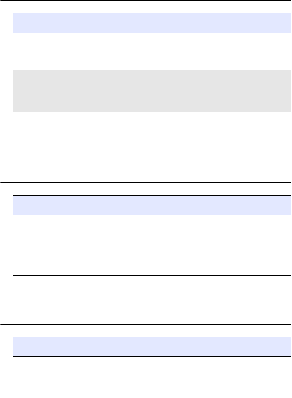
General Commands Reference Guide S | 80
©
1989-2024 Lauterbach
Step.BackChange Step back until expression changes
Steps back till the expression changes. The command will stop also, if the expression cannot be evaluated.
Example:
See also
■ Step ■ Step.single
▲ ’Release Information’ in ’Legacy Release History’
Step.BackOver Step back over call
This command can only be used together with the Context Tracking System (CTS). The command steps
back one assembler instruction or one HLL line.
Under certain conditions, the command automatically activates CTS when it is turned off.
See also
■ Step ■ Step.single
▲ ’Release Information’ in ’Legacy Release History’
Step.BackTill Step back until expression true
Steps back till the boolean expression becomes true. The command will stop also, if the expression cannot
be evaluated.
Format: Step.BackChange
Step.BackChange Register(A7) ; steps till register A7 changes
Step.BackChange
Data.Long(sd:0x100)
; steps till the longword at
location
; 100 changes
Format: Step.BackOver
Format: Step.BackTill [<boolean_expression>]

General Commands Reference Guide S | 81
©
1989-2024 Lauterbach
Example:
See also
■ Step ■ Step.single
Step.Change Step until expression changes
Steps till the expression changes. The command will stop also, if the expression cannot be evaluated.
Example:
See also
■ Step ■ Step.single
Step.BackTill Register(A7)>0x1000 ; steps till register A7 is larger
; than 1000
Step.BackTill
Data.Long(sd:0x100)==0x0
; steps till the longword at
; location 100 gets the value 0
Format: Step.Change [<expression>]
Step.Change Register(A7) ; steps till register A7 changes
Step.Change Data.Long(SD:0x100) ; steps till the long word at
; location 100 changes

General Commands Reference Guide S | 82
©
1989-2024 Lauterbach
Step.Diverge Step to next unreached line
The Step.Diverge command can be used to exit loops or to fast forward to not yet reached HLL lines. It
performs Step.Over repeatedly until an HLL line is reached which has not been reached in the previous
steps.
TRACE32 maintains a list of all HLL lines which were already reached. These reached lines are marked with
a slim grey line in the List window (see picture below).
In ASM/MIX mode, Step.Diverge applies to assembler code lines instead of HLL lines.
The reached lines list is cleared when you use the Go.direct command without address or the Break
command while the program execution is stopped.
The reached lines list is not cleared at the following commands:
• Step.single, Step.Over, Step.Change <expression>, Step.Till <condition>
• Var.Step.Change <hll_expression>, Var.Step.Till <hll_condition>
• Go.Return, Go.Up, Go.direct <address>
• Var.Go.direct <hll_expression>
Format: Step.Diverge


General Commands Reference Guide S | 84
©
1989-2024 Lauterbach
Step.Hll Step in HLL-mode
Similar to the Step.single command, except that simultaneous switching into high-level language mode
occurs.
See also
■ Step ■ Step.Mix ■ Step.single
▲ ’Release Information’ in ’Legacy Release History’
Step.Mix Step in mixed-mode
Similar to the Step.single command, except that simultaneous switching into mixed mode takes place.
See also
■ Step ■ Step.Hll ■ Step.single
Format: Step.Hll [<count>]
Format: Step.Mix [<count>]

General Commands Reference Guide S | 85
©
1989-2024 Lauterbach
Step.Over Step over call
Steps within a function and runs called functions in real-time.
The method for this command is depends, whether the operation-mode is HLL or assembler (ASM/MIX).
See also
■ Step ■ Step.single
▲ ’Release Information’ in ’Legacy Release History’
Step.single Single-step
Executes one program step until the next assembler instruction or HLL line, depending on the current debug
mode, is reached. <count> is the number of command executions (default is 1).
Examples:
See also
■ Step ■ Step.Asm ■ Step.Back ■ Step.BackChange
■ Step.BackOver ■ Step.BackTill ■ Step.Change ■ Step.Diverge
■ Step.Hll ■ Step.Mix ■ Step.Over ■ Step.Till
■ SETUP.IMASKASM ■ SETUP.IMASKHLL ■ Var.Step
Format: Step.Over
ASM In assembler mode the debugger reads the instruction at the current PC.
On a CALL instruction a Go.Next command is executed. All other
instructions will cause a regular single-step command.
HLL In HLL mode the system first executes an HLL single-step. After this step
it checks, whether the PC is still in the same function. If the PC has left
the function it will check the value addressed by the SP. With that value
being within the original function, the program is continued to that point. If
this address contains no HLL breakpoint the above procedure will be
repeated (HLL step …).
Format: Step.single [<count>]
Step.single
Step.single 10.
; single step
; 10 steps
General Commands Reference Guide S | 86
©
1989-2024 Lauterbach
Step.Till Step until expression true
Steps till the boolean expression becomes true. The command will stop also if the expression cannot be
evaluated.
Examples:
See also
■ Step ■ Step.single
Format: Step.Till [<boolean_expression>]
Step.Till Register(A7)>0x1000 ; steps till register A7 is larger
; than 1000
Step.Till Data.Long(SD:0x100)==0x0 ; steps till the long word at
; location 100 gets the value 0

General Commands Reference Guide S | 87
©
1989-2024 Lauterbach
STM
STM System trace configuration
STM by ARM, STM and STDI by Texas Instruments
A system trace is a hardware module on a SoC which enables the developer to output predefined hardware
or software messages without affecting the run-time behavior of the system.
For a description of the STM commands, see “System Trace User’s Guide” (trace_stm.pdf).

General Commands Reference Guide S | 88
©
1989-2024 Lauterbach
STOre
STOre Store settings as PRACTICE script
Stores settings in the format of a PRACTICE script (*.cmm). The script can be executed by using the DO
command.
Format: STOre <file> [[%<format>]<item> …] [/<option>]
<format>: sYmbol | NosYmbol
<item>: default | ALL | Win | WinPAGE | WinTOP | SYStem …
<option>: NoDate
<format> Description
sYmbol Addresses (e.g. for the commands Break or GROUP) are stored as
symbols. With this option, breakpoints can be stored and recalled for a
newer version of the program with different addresses. The keyword must
be entered before the item which shall be stored. The default can be set
with SETUP.STOre.SYMBOLIC.
NosYmbol Addresses (e.g. for the commands Break or GROUP) are stored as scalar
values (plain hex). With this option, stored breakpoints can be recalled
when no debug symbols are available. The keyword must be entered
before the item which shall be stored.
<item> Description
no item specified If no item is specified, then the default setting is used; see default below.
AREA Store the current AREA settings.
ALL Store all settings.
Analyzer See Analyzer command.
AnalyzerFocus Save the current AUTOFOCUS configuration to a file.
ART See ART command.
BookMark Store the settings of trace bookmarks and address bookmarks - see
BookMark command.
To export bookmarks as an XML file, see BookMark.EXPORT.
Break Store breakpoints - see Break command.
BSDL Store the boundary scan settings. See BSDL command.

General Commands Reference Guide S | 89
©
1989-2024 Lauterbach
CAnalyzer See CAnalyzer command.
CAnalyzerFocus Store the electrical settings for the CAnalyzer. See
CAnalyzer.ShowFocus.
CIProbe See CIProbe command.
Count See Count command.
default Some settings are stored by default, except for the window setting.
EDITOR Store the auto-indentation settings, etc. for all TRACE32 editors. See
SETUP.EDITOR.
FDX See FDX command.
FLASH (For diagnostic purposes only.) Store the FLASH declaration displayed in
the FLASH.List window and the settings made with the FLASH.TARGET
command.
GLOBAL Stores global PRACTICE macros with the current values - see GLOBAL
command.
GROUP See GROUP command.
HELP Stores help settings and bookmarks - see HELP command
HISTory See HISTory command.
LA Logic Analyzer - see LA command.
LOGGER See LOGGER command.
MAP See MAP command.
MARKER See sYmbol.MARKER.
NAME See NAME command.
NoDate
(deprecated)
Omit the date at the beginning of the generated script. Use the option
/NoDate instead.
This item is deprecated since Sep/2023.
On-chip See Onchip command.
PBREAK Stores the breakpoints created for PRACTICE scripts (*.cmm). See
PBREAK command group.
PERF Performance Analyzer - see PERF command.
POD See POD command.
Register, RegSet See Register command.
SNOOP See
SNOOP command.
SPATH Source search path - see sYmbol.SPATH command.
SPATHCACHE Stores cached directories from the sYmbol.SPATH command.
<item> Description

General Commands Reference Guide S | 90
©
1989-2024 Lauterbach
Example: executing the following STOre command in TRACE32 PowerView for ARM64 connected to Zynq-
Ultrascale+ processor
Symbolic | HEX
(deprecated)
Addresses are stored as symbols or scalar values (plain hex). Use the
format parameter %sYmbol or %NosYmbol instead.
SYnch See SYnch command.
SYStem See SYS command.
TRANSlation Store all static address TRANSlations as well as all common, transparent
and protected address ranges as displayed by command
TRANSlation.List.
TrOnchip Trigger Onchip - see TrOnchip command.
TrPOD Trigger Probe - see TP command.
VCO See VCO command.
Win Store entire window configuration.
WinPAGE Store the current window page. See WinPAGE command.
WinTOP Store the active window. See WinTOP command.
<option> Description
NoDate Omit the comment containing the current date at the beginning of the
generated PRACTICE script file (*.cmm).
STOre ~~~\test.cmm SYStem
<item> Description

General Commands Reference Guide S | 91
©
1989-2024 Lauterbach
produces the following file:
See also
■ AutoSTOre ■ BookMark.List ■ ClipSTOre ■ SETUP.QUITDO
■ SETUP.STOre
B::
SYStem.RESet
SYStem.CPU ZYNQ-ULTRASCALE+-APU
SYStem.CONFIG CoreNumber 4.
SYStem.CONFIG CORE 1. 1.
CORE.ASSIGN 1. 2. 3. 4.
SYStem.MemAccess DAP
SYStem.CpuBreak Enable
SYStem.CpuSpot Enable
SYStem.JtagClock 10.MHz
SYStem.Option.MMUPLM OFF
SYStem.Option.ENRESET OFF
SYStem.Option.TRST OFF
SYStem.CONFIG.DAPIRPRE 0.
SYStem.CONFIG.DAPDRPRE 0.
SYStem.CONFIG.DAPIRPOST 12.
SYStem.CONFIG.DAPDRPOST 1.
SYStem.CONFIG.SLAVE OFF
SYStem.CONFIG.TAPState SELectDRscan
SYStem.Mode Up
ENDDO
General Commands Reference Guide S | 92
©
1989-2024 Lauterbach
SVE
SVE Access the scalable vector extension SVE
This command group allows to access the scalable vector extension (SVE). They are available for the
processor architecture ARMv8.2 and newer.
SVE.Init Initialize SVE registers
Sets the SVE registers to their default values.
SVE.RESet Reset SVE settings
Resets debugger SVE settings.
SVE.Set Modify SVE registers
Allows to modify SVE registers. Predicate registers and the FFR cannot be modified.
Registers can be modified with either floating-point values, or hexadecimal values.
Format: SVE.Init
Format: SVE.RESet
Format: SVE.Set

General Commands Reference Guide S | 93
©
1989-2024 Lauterbach
SVE.view Display SVE registers
All accessible SVE registers are displayed in a window. The contents of this window depend on the
implemented vector size.
The FFR register cannot be displayed. Predicate registers are read only.
Format: SVE.view

General Commands Reference Guide S | 94
©
1989-2024 Lauterbach
sYmbol
sYmbol Debug symbols
See also
■ sYmbol.AddInfo ■ sYmbol.AutoLOAD ■ sYmbol.Browse ■ sYmbol.CASE
■ sYmbol.CHECK ■ sYmbol.Class ■ sYmbol.CLEANUP ■ sYmbol.ColorCode
■ sYmbol.ColorDef ■ sYmbol.CREATE ■ sYmbol.CUTLINE ■ sYmbol.Delete
■ sYmbol.DeleteMACRO ■ sYmbol.DeletePATtern ■ sYmbol.DEMangle ■ sYmbol.DEOBFUSCATE
■ sYmbol.DONE ■ sYmbol.ECA ■ sYmbol.ForEach ■ sYmbol.INFO
■ sYmbol.LANGUAGE ■ sYmbol.List ■ sYmbol.LSTLOAD ■ sYmbol.MARKER
■ sYmbol.MATCH ■ sYmbol.MEMory ■ sYmbol.Modify ■ sYmbol.name
■ sYmbol.NAMESPACES ■ sYmbol.NEW ■ sYmbol.OVERLAY ■ sYmbol.PATCH
■ sYmbol.POINTER ■ sYmbol.POSTFIX ■ sYmbol.PREFIX ■ sYmbol.RELOCate
■ sYmbol.RESet ■ sYmbol.SourceBeautify ■ sYmbol.SourceCONVert ■ sYmbol.SourceLOAD
■ sYmbol.SourcePATH ■ sYmbol.SourceRELOAD ■ sYmbol.STATE ■ sYmbol.STRIP
■ sYmbol.TYPEINFO ■ sYmbol.View
▲ ’sYmbol Functions’ in ’General Function Reference’
▲ ’Release Information’ in ’Legacy Release History’
Overview sYmbol
Using the sYmbol command group, you can list, browse, or modify existing symbols and create new
symbols.
Symbolic information is stored in several tables combined with one another. For details about the syntax of
symbols, search paths and C++ support, refer to the description of the Var command group.
Statics Contains all static symbols, i.e. symbols with a fixed address. The symbol
may be local related to a function, a module or a program.
Functions Contains all function blocks and additional information about functions,
i.e. virtual frame pointers, register usage, stack frame layout.
Locals All local symbols of a function. The ranges of validity are also contained
in this table.
Modules A module is one separately compiled program unit, i.e. one source file.
Types High level language types and the physical description. Only named
types are included in this table.
Sources Contains a list of all HLL source files and the path names to the sources.
SPATH List of directories of the source search path.

General Commands Reference Guide S | 95
©
1989-2024 Lauterbach
PRACTICE Functions
Refer to “sYmbol Functions” in General Function Reference, page 303 (general_func.pdf).
Lines High level language source lines, respectively blocks. On one address
can be one high level language block only.
Sections Logical and physical program address ranges. According to the compiler
a differentiation between 'CODE', 'DATA', 'BSS', 'ROMABLE' etc. is made.
For each section special access rights are valid.
Programs Usually only one program is loaded. If more than one has been loaded,
the option NoClear must be used together with the Data.LOAD
command.
Stacks Contains information about the stack frame. Usually this is the offset
between a register in the processor and a “virtual frame pointer”. This
information is needed when there is no real frame pointer register used
by highly optimizing compilers.
Attributes This table is target dependent. It may contain information about different
processor executing environments (e.g. ARM/Thumb) or special code
constructs (e.g. jump tables or literal data in code).
Macros Contains the contents of preprocessor macros. This information is not
available for all compilers. However it may be generated manually with
the sYmbol.CREATE.MACRO command.
Map Holds a log of all memory operations during download. Only maintained
when the option MAP was set with the load command.
Compilers This listing contains compiler specific information. It cannot be displayed
and is determined on internal use by the HLL debugger

General Commands Reference Guide S | 96
©
1989-2024 Lauterbach
sYmbol.AddInfo Provide additional symbolic information
The command can provide additional information about structures, pointers or variables. The information
can scale the display, make typecasts or provide application specific interpretation of information (e.g. C++
descriptor displays).
Here is a list of additional symbolic information types that can be set (not all symbolic information types are
available depending on what the information is assigned to):
Format: sYmbol.AddInfo
Scaled <multiplier>
[<offset>
<explanation>]]
Scales the value of the element:
trueValue = (srcValue * multiplier) + offset.
RScaled <multiplier>
[<offset>
[<explanation>]]
Scales the value of the element:
trueValue = (multiplier / srcValue) + offset
<explanation> Any user-defined text, such as class name, meaning, type, unit of
measurement, etc. (See example)
JSTRING Handles the element as pointer pointing to a string stored in the Java
jstring representation. (See example)
NSTRING <bitmask> Handles the element as pointer pointing to a structure, where the first
element is the string length and the next element is the string. (See
example)
ZSTRING Handles the element as pointer pointing to a C-like string (string
terminated by zero). (See example)
MaskedPointer
<mask> [<offset>]
Modifies the pointer target address:
truePointer = (srcPointer & mask) | offset
(See example)
MostDerived
<struct/class_name>
Forces data referenced by a pointer to be displayed as data of the
declared struct or class (See example)
DESCRIPTOR Forces data references by a pointer to be displayed according to a
descriptor.
ENUM
<item_value>
<item_name>
Adds a name for a value inside a variable.
Hex Marks the element to be displayed in hexadecimal.
Decimal Marks the element to be displayed in decimal.

General Commands Reference Guide S | 97
©
1989-2024 Lauterbach
See also
■ sYmbol.AddInfo.Address ■ sYmbol.AddInfo.Delete
■ sYmbol.AddInfo.LINK ■ sYmbol.AddInfo.List
■ sYmbol.AddInfo.LOADASAP2 ■ sYmbol.AddInfo.Member
■ sYmbol.AddInfo.RESet ■ sYmbol.AddInfo.Type
■ sYmbol.AddInfo.Var ■ sYmbol
Ascii Marks the element to be displayed as ASCII.
sYmbol Marks the element to be displayed as a pointer to a symbol.
HIDE Hides the element from watch windows.
BigEndian Forces access to element in BigEndian byte order.
LittleEndian Forces access to element in LittleEndian byte order.
LINK <link_name> Format an element as defined by the sYmbol.AddInfo.LINK command.

General Commands Reference Guide S | 98
©
1989-2024 Lauterbach
sYmbol.AddInfo.Address Add symbol information to fixed address
Adds scaling information to an address or an address range. All symbolic information types are described in
sYmbol.AddInfo.
Example 1:
Example 2:
See also
■ sYmbol.AddInfo
Format: sYmbol.AddInfo.Address <range> | <address> <info> [<parameters>]
<info>: Scaled <multiplier> [<offset> [<explanation>]]
RScaled <multiplier> [<offset> [<explanation>]]
…
; multiply each HLL variable that is located in the address range
; 0xA1080000++0xff by 1.34 and add 10. Use mVolt as unit
sYmbol.AddInfo.Address 0xA1080000++0xff Scaled 1.34 +10. " mVolt"
; multiply the reciprocal contents of each HLL variable that is located
; in the address range 0xA1080000++0xff by 20. and add +3.3. Use mA as
; unit
sYmbol.AddInfo.Address 0xA1080000++0xff RScaled 20. +3.3 " mA"

General Commands Reference Guide S | 99
©
1989-2024 Lauterbach
sYmbol.AddInfo.Delete Delete information
Deletes existing information from the given variable or type name.
Example:
See also
■ sYmbol.AddInfo ■ sYmbol.AddInfo.RESet
Format: sYmbol.AddInfo.Delete <name>
sYmbol.AddInfo.Var cstr1 ZSTRING
sYmbol.AddInfo.Delete "cstr1"

General Commands Reference Guide S | 100
©
1989-2024 Lauterbach
sYmbol.AddInfo.LINK Define information for "sYmbol.AddInfo" commands
Defines information for other sYmbol.AddInfo commands. All symbolic information types are described in
sYmbol.AddInfo.
Example:
See also
■ sYmbol.AddInfo
Format: sYmbol.AddInfo.LINK <link_name> <info> [<parameters>]
<info>: NSTRING <bitmask>
JSTRING
ZSTRING
MostDerived <struct | class>
DESCRIPTOR <bitmask> <struct | class>
...
sYmbol.AddInfo.List
;1. create description group 'seasons'
;2. link meaningful description to each numerical value
sYmbol.AddInfo.LINK seasons enum 0 "spring"
sYmbol.AddInfo.LINK seasons enum 1 "summer"
sYmbol.AddInfo.LINK seasons enum 2 "autumn"
sYmbol.AddInfo.LINK seasons enum 3 "winter"
; equivalent to C statement symbols for
; "enum seasons {spring, summer, autumn, winter};"
;link the integer variables to the description group 'seasons'
sYmbol.AddInfo.Var mcount LINK seasons
sYmbol.AddInfo.Var mstatic1 LINK seasons
Var.Watch
Var.AddWatch mcount
Var.AddWatch mstatic1
Var.set mcount=0
Var.set mstatic1=1

General Commands Reference Guide S | 101
©
1989-2024 Lauterbach
sYmbol.AddInfo.List List additional information
Shows all available additional information which has been declared by sYmbol.AddInfo commands.
See also
■ sYmbol.AddInfo
sYmbol.AddInfo.LOADASAP2 Load scaling information from ASAP2 file
Loads the scaling and physical unit information from an ASAP2 file.
See also
■ sYmbol.AddInfo ■ Data.LOAD.ASAP2
▲ ’Release Information’ in ’Legacy Release History’
Format: sYmbol.AddInfo.List
Format: sYmbol.AddInfo.LOADASAP2 <file>

General Commands Reference Guide S | 102
©
1989-2024 Lauterbach
sYmbol.AddInfo.Member Add information to member of struct
Add information to specific member of a specific struct or class. All symbolic information types are
described in sYmbol.AddInfo.
Example 1
Format: sYmbol.AddInfo.Member <type> <member> <info> [<parameters>]
<info>: Scaled <multiplier> [<offset> [<explanation>]]
RScaled <multiplier> [<offset> [<explanation>]]
ZSTRING
MaskedPointer <mask> <offset>
MostDerived <struct/class_name>
...
<type> Name of struct or class.
<member> Name of struct or class element.
sYmbol.AddInfo.Member neste c Scaled 3.4
sYmbol.AddInfo.Member nesta a Scaled 6.3

General Commands Reference Guide S | 103
©
1989-2024 Lauterbach
Example 2
A masked pointer is a pointer where only a part of the “pointer value” is stored. In the following example, the
element ast->right is a value, whose lower 17 bits are the part of an address. The target address is
calculated using the lower 17 bits and adding 0x22200000 as base address. The pointer in this example is
declared using the command:
Example 3
C Code:
PRACTICE script:
See also
■ sYmbol.AddInfo
sYmbol.AddInfo.Member strtype1 right MaskedPointer 0x0001FFFF 0x22200000
struct example{ uint32 mode : 2; } instance;
enum values { on = 0, off, flicker };
; <class_name> <member> ENUM <item_value> <item_name>
sYmbol.AddInfo.Member example mode ENUM 0 "on"
sYmbol.AddInfo.Member example mode ENUM 1 "off"
sYmbol.AddInfo.Member example mode ENUM 2 "flicker"
sYmbol.CREATE.MACRO on 0
sYmbol.CREATE.MACRO off 1
sYmbol.CREATE.MACRO flicker 2
sYmbol.CREATE.Done
Var.Set instance.mode=flicker

General Commands Reference Guide S | 104
©
1989-2024 Lauterbach
sYmbol.AddInfo.RESet Remove all additional information
Removes all additional information.
See also
■ sYmbol.AddInfo ■ sYmbol.AddInfo.Delete
sYmbol.AddInfo.Type Add information to a data type
Add information to a specific data type. All symbolic information types are described in sYmbol.AddInfo.
The following shows examples to display Symbian OS descriptors and strings correctly in the debugger
window.
See also
■ sYmbol.AddInfo
Format: sYmbol.AddInfo.RESet
Format: sYmbol.AddInfo.Type <type> <info> [<parameters>]
<info>: NSTRING <bitmask>
JSTRING
ZSTRING
MostDerived <struct | class>
DESCRIPTOR <bitmask> <struct | class>
...
sYmbol.AddInfo.Type tdef2 ZSTRING ; the data type tdef2 is a zero-
; terminated string
sYmbol.AddInfo.Type "TDesC16" DESCRIPTOR 0x1xxxxxxx "TPtrC16"
sYmbol.AddInfo.Type "TPtrC8" NSTRING 0x0xxxxxxx
sYmbol.AddInfo.Type nextx MostDerived "TreeMFPtr"

General Commands Reference Guide S | 105
©
1989-2024 Lauterbach
sYmbol.AddInfo.Var Add information to a variable
Adds type information to a variable. All symbolic information types are described in sYmbol.AddInfo.
Example:
See also
■ sYmbol.AddInfo
Format: sYmbol.AddInfo.Var <var> <info> [<parameters>]
<info>: Scaled <multiplier> [<offset> [<explanation>]]
RScaled <multiplier> [<offset> [<explanation>]]
ZSTRING
MaskedPointer <mask> <offset>
MostDerived <string>
...
sYmbol.AddInfo.Var cstr1 ZSTRING ;The contents of cstr1 is a zero-
;terminated string
sYmbol.AddInfo.List ;Display definition list

General Commands Reference Guide S | 106
©
1989-2024 Lauterbach
sYmbol.AutoLOAD Automated loading of symbols
The command sYmbol.AutoLOAD allows to automate the loading of symbol files. This is helpful if a boot
loader or an RTOS downloads code to the target. To debug this downloaded code loading of the appropriate
symbol information is required.
The sYmbol.AutoLOAD command maintains a list for automatic loading of symbol information. This list
contains:
• A list of address ranges
• For each address range a component name and an appropriate load command
Whenever the user wants to display an address within a specified address range, and TRACE32 also needs
symbol information for the display, the appropriate load command is automatically started.
See also
■ sYmbol.AutoLOAD.CHECK ■ sYmbol.AutoLOAD.CHECKCoMmanD
■ sYmbol.AutoLOAD.CHECKDLL ■ sYmbol.AutoLOAD.CHECKEPOC
■ sYmbol.AutoLOAD.CHECKLINUX ■ sYmbol.AutoLOAD.CHECKQNX
■ sYmbol.AutoLOAD.CHECKUEFI ■ sYmbol.AutoLOAD.CHECKWIN
■ sYmbol.AutoLOAD.CHECKWINCE ■ sYmbol.AutoLOAD.CLEAR
■ sYmbol.AutoLOAD.config ■ sYmbol.AutoLOAD.Create
■ sYmbol.AutoLOAD.Delete ■ sYmbol.AutoLOAD.List
■ sYmbol.AutoLOAD.LOADEPOC ■ sYmbol.AutoLOAD.RESet
■ sYmbol.AutoLOAD.SET ■ sYmbol.AutoLOAD.TOUCH
■ sYmbol
Format: sYmbol.AutoLOAD.<sub_cmd>

General Commands Reference Guide S | 107
©
1989-2024 Lauterbach
sYmbol.AutoLOAD.CHECK Update autoloader table
A single sYmbol.AutoLOAD.CHECK command triggers the refresh of the Autoloader table
(sYmbol.AutoLOAD.List).
See also
■ sYmbol.AutoLOAD ■ sYmbol.AutoLOAD.config
Format: sYmbol.AutoLOAD.CHECK [now [/<option>] | ON | OFF | ONGO]
<option>: MACHINE <machine_magic> | <machine_id> | <machine_name>
now Update the Autoloader table now.
ON If set to ON, TRACE32 updates the autoloader table after every single step
and whenever the program execution is stopped. This significantly slows
down the speed of TRACE32.
OFF If set to OFF, no automatic update of the autoloader table is done.
ONGO TRACE32 updates the autoloader table whenever the program execution is
stopped.
MACHINE Updates the autoloader table only for the specified machine.
See also “What to know about the Machine Parameters”
(general_ref_t.pdf).

General Commands Reference Guide S | 108
©
1989-2024 Lauterbach
sYmbol.AutoLOAD.CHECKCoMmanD Configure dynamic autoloader
The dynamic autoloader reads the target’s component table and fills the autoloader list with the components
found on the target. All necessary information, such as load addresses and space IDs, are retrieved from
kernel-internal information. The dynamic autoloader is activated by the command
sYmbol.AutoLOAD.CHECK.
Example:
This command needs an OS Awareness configured for the OS running on the target. Please see the OS
Awareness Manuals (rtos_<os>.pdf) for further information.
See also
■ sYmbol.AutoLOAD ■ sYmbol.AutoLOAD.config
❏ sYmbol.AutoLOAD.CHECKCMD()
Format: sYmbol.AutoLOAD.CHECKCoMmanD <load_command> [/<option>]
<option>: MACHINE <machine_magic> | <machine_id> | <machine_name>
<load_command> If an address is accessed that is covered by the autoloader list, the
autoloader calls <load_command> and appends the load addresses and the
space ID of the component to the action. Usually, <load_command> is a call
to a PRACTICE script (*.cmm) that handles the parameters and loads the
symbols. Please see the example scripts in the ~~/demo directory.
MACHINE Allows to specify different autoloader scripts for different machines.
See also “What to know about the Machine Parameters”
(general_ref_t.pdf).
sYmbol.AutoLOAD.CHECKCoMmanD "DO autoload"
sYmbol.AutoLOAD.CHECK
sYmbol.AutoLOAD.List
NOTE: The dynamic autoloader covers only components that are already started.
Components that are not in the current process/library table are not covered.

General Commands Reference Guide S | 109
©
1989-2024 Lauterbach
sYmbol.AutoLOAD.CHECKDLL Configure automatic DLL file loader
This command can only be used with Texas Instruments DSPs.
If the symbol __DLModules is not available, please specify the <address> for the automatic DLL file loader.
If no <load_command> is specified DO autoload is used. The automatic DLL file loader is activated by the
command sYmbol.AutoLOAD.CHECK.
Please refer also to the examples in ~~/demo/c5000/etc/dll/
See also
■ sYmbol.AutoLOAD ■ sYmbol.AutoLOAD.config
Format: sYmbol.AutoLOAD.CHECKDLL [<address>] [<load_command>]

General Commands Reference Guide S | 110
©
1989-2024 Lauterbach
sYmbol.AutoLOAD.CHECKEPOC Dynamic autoloader for Symbian
The dynamic autoloader reads the target’s process table and fills the autoloader list with the modules found
on the target. All necessary information, such as load addresses and space IDs, are retrieved from kernel-
internal information. The dynamic autoloader also covers dynamically loaded modules. The dynamic
autoloader is activated by the command sYmbol.AutoLOAD.CHECK.
If an address is accessed that is covered by the autoloader list, the autoloader calls <load_command> and
appends the load addresses and the space ID of the module to the action. Usually, <load_command> is a
call to a PRACTICE script (*.cmm) that handles the parameters and loads the symbols. Please see the
example scripts in the ~~/demo directory.
Example:
See also
■ sYmbol.AutoLOAD ■ sYmbol.AutoLOAD.config
sYmbol.AutoLOAD.CHECKLINUX Configure autoloader for Linux debugging
This command is deprecated. Use sYmbol.AutoLOAD.CHECKCoMmanD instead.
See also
■ sYmbol.AutoLOAD ■ sYmbol.AutoLOAD.config
Format: sYmbol.AutoLOAD.CHECKEPOC <load_command>
sYmbol.AutoLOAD.CHECKEPOC "DO autoload.cmm"
NOTE:
• The dynamic autoloader covers only modules that are already started.
Modules that are not in the current process/library table are not covered.
• If a process symbol file is loaded, the dynamic autoloader adds the space
ID, which may be used to load the symbols to the appropriate space.
Format: sYmbol.AutoLOAD.CHECKLINUX <action> (deprecated)

General Commands Reference Guide S | 111
©
1989-2024 Lauterbach
sYmbol.AutoLOAD.CHECKQNX Configure autoloader for QNX debugging
This command is deprecated. Use sYmbol.AutoLOAD.CHECKCoMmanD instead.
See also
■ sYmbol.AutoLOAD
sYmbol.AutoLOAD.CHECKUEFI Configure autoloader for UEFI debugging
The UEFI code is provided by the boot FLASH, but debugging becomes more comfortable when debug
symbols are available. TRACE32 uses the so-called Autoloader to realize the automatic loading of debug
symbols whenever they are required.
The command sYmbol.AutoLOAD.CHECKUEFI specifies the command that is automatically used by the
Autoloader to load the symbol information. Usually a script called autoload.cmm provided by Lauterbach
is used.
The command sYmbol.AutoLOAD.CHECKUEFI implicitly also defines the parameters that TRACE32 uses
internally for the Autoloader (see screenshot below).
When the Autoloader is configured, the command sYmbol.AutoLOAD.CHECK can be used to scan the
UEFI module table and to activate the Autoloader. The command sYmbol.AutoLOAD.List allows to inspect
the scanned module information.
Format: sYmbol.AutoLOAD.CHECKQNX <action> (deprecated)
Format: sYmbol.AutoLOAD.CHECKUEFI <load_command>

General Commands Reference Guide S | 112
©
1989-2024 Lauterbach
Since the UEFI module table is updated by UEFI, a re-scan might be necessary.
See also
■ sYmbol.AutoLOAD ■ sYmbol.AutoLOAD.config
sYmbol.AutoLOAD.CHECKWIN Configure autoloader
This command is deprecated. Use sYmbol.AutoLOAD.CHECKCoMmanD instead.
See also
■ sYmbol.AutoLOAD
sYmbol.AutoLOAD.CHECKWINCE Configure autoloader
This command is deprecated. Use sYmbol.AutoLOAD.CHECKCoMmanD instead.
See also
■ sYmbol.AutoLOAD
sYmbol.AutoLOAD.CHECKUEFI \
"DO ~~/demo/x86/bootloader/uefi/h2o/autoload.cmm"
sYmbol.AutoLOAD.CHECK
sYmbol.AutoLOAD.List
Format: sYmbol.AutoLOAD.CHECKWIN <action> (deprecated)
Format: sYmbol.AutoLOAD.CHECKWINCE <action> (deprecated)
AutoLoader parameter list

General Commands Reference Guide S | 113
©
1989-2024 Lauterbach
sYmbol.AutoLOAD.CLEAR Remove symbol information
Removes symbol information for the specified <address> or <component_name>.
Examples:
See also
■ sYmbol.AutoLOAD
sYmbol.AutoLOAD.config Configure symbol autoloader
Opens a configuration dialog for the symbol autoloader.
See also
■ sYmbol.AutoLOAD ■ sYmbol.AutoLOAD.CHECK
■ sYmbol.AutoLOAD.CHECKCoMmanD ■ sYmbol.AutoLOAD.CHECKDLL
■ sYmbol.AutoLOAD.CHECKEPOC ■ sYmbol.AutoLOAD.CHECKLINUX
■ sYmbol.AutoLOAD.CHECKUEFI ■ sYmbol.AutoLOAD.List
❏ sYmbol.AutoLOAD.CONFIG()
Format: sYmbol.AutoLOAD.CLEAR <address> | <component_name> [/<option>]
<option>: MACHINE <machine_magic> | <machine_id> | <machine_name>
MACHINE Removes symbol information only for the specified machine.
See also “What to know about the Machine Parameters”
(general_ref_t.pdf).
sYmbol.AutoLOAD.CLEAR C:0x5009B420
sYmbol.AutoLOAD.CLEAR "*trkengine*"
Format: sYmbol.AutoLOAD.config

General Commands Reference Guide S | 114
©
1989-2024 Lauterbach
sYmbol.AutoLOAD.Create Create entry for autoloader table
Specify an entry for the Autoloader table. The complete Autoloader table can be displayed with the
sYmbol.AutoLOAD.List command.
Example:
See also
■ sYmbol.AutoLOAD
sYmbol.AutoLOAD.Delete Delete autoloader entries
Deletes entries from the autoloader table. Without parameters, this commands clears the entire autoloader
table.
Example:
See also
■ sYmbol.AutoLOAD
Format: sYmbol.AutoLOAD.Create <range> <component_name> <load_command>
<component_name> Is the TRACE32 internal name for the symbol file. Please use the command
sYmbol.List.Program to get this name.
<load_command> Can be either a command of the Data.LOAD command group or a
PRACTICE script (*.cmm).
sYmbol.AutoLOAD.Create 0x1000--0x2fff "thumble" \
"Data.LOAD.Elf thumble.axf /NoClear /NoCODE"
sYmbol.AutoLOAD.Create 0x10000--0x1ffff "can" "DO Load_CAN"
Format: sYmbol.AutoLOAD.Delete [<name> | <address>]
sYmbol.AutoLOAD.Delete "init"


General Commands Reference Guide S | 116
©
1989-2024 Lauterbach
sYmbol.AutoLOAD.LOADEPOC Definition for static autoloader for Symbian
When generating a Symbian OS ROM image (e.g. with “buildrom”), the builder generates a log file as well
(usually “rombuild.log”). This log file contains the section addresses of all modules included in the image.
The static autoloader reads this log file and fills the autoloader list with the modules found in the log file with
it’s appropriate load addresses.
If an address is accessed that is covered by the autoloader list, the autoloader calls <load_command> and
appends the load addresses of the module to the action. Usually, <load_command> is a call to a PRACTICE
script that handles the parameters and loads the symbols. Please see the example scripts in the ~~/demo
directory.
Example:
See also
■ sYmbol.AutoLOAD
Format: sYmbol.AutoLOAD.LOADEPOC <log_file> <load_command> [/<option>]
<option>: StripPATH | CutPATH | LowerPATH
StripPART <number> | <string>
NOTE:
• The static autoloader addresses only modules that are linked into the
ROM image. Modules loaded to the target dynamically are not covered.
• The log file does not include the process ID that a process will get when
started. Thus, the static autoloader loads the symbols of a process to
space ID zero.
sYmbol.AutoLOAD.LOADEPOC "la_001.techview.log" "DO autoload.cmm"

General Commands Reference Guide S | 117
©
1989-2024 Lauterbach
sYmbol.AutoLOAD.RESet Reset autoloader
Clears the autoloader table.
See also
■ sYmbol.AutoLOAD
sYmbol.AutoLOAD.SET Mark symbol information manually as loaded
The command sYmbol.AutoLOAD.Set allows to manually mark symbol information as loaded. This is
helpful to suppress an error message when no symbol information was generated for a specified address or
component range.
Example:
See also
■ sYmbol.AutoLOAD
Format: sYmbol.AutoLOAD.RESet
Format: sYmbol.AutoLOAD.SET <name> | <address> | <addressrange>
sYmbol.AutoLOAD.SET 0x5015E030
sYmbol.AutoLOAD.SET "*efsrv*"

General Commands Reference Guide S | 118
©
1989-2024 Lauterbach
sYmbol.AutoLOAD.TOUCH Initiate automatic loading by command
Initiates the loading of symbol information as defined by the sYmbol.AutoLOAD.CHECKCoMmanD.
Examples:
See also
■ sYmbol.AutoLOAD
Format: sYmbol.AutoLOAD.TOUCH <component_name> | <addressrange> |
<address> [/<option>]
<option>: MACHINE <machine_magic> | <machine_id> | <machine_name>
<component_name> Wildcards possible.
<address> Any address within the address range used by a component.
<addressrange> Touches all components mapped within the given address, e.g.
librairies of a single process.
MACHINE Touches only the component of the specified machine.
See also “What to know about the Machine Parameters”
(general_ref_t.pdf).
sYmbol.AutoLOAD.TOUCH "*efsrv*"
sYmbol.AutoLOAD.TOUCH 0x50011f9c

General Commands Reference Guide S | 119
©
1989-2024 Lauterbach
sYmbol.Browse Browse symbols
See also
■ sYmbol.Browse.Class ■ sYmbol.Browse.Enum ■ sYmbol.Browse.Function ■ sYmbol.Browse.Module
■ sYmbol.Browse.MVar ■ sYmbol.Browse.name ■ sYmbol.Browse.SFunction ■ sYmbol.Browse.SModule
■ sYmbol.Browse.SOURCE ■ sYmbol.Browse.Struct ■ sYmbol.Browse.sYmbol ■ sYmbol.Browse.Type
■ sYmbol.Browse.TypeDef ■ sYmbol.Browse.Union ■ sYmbol.Browse.Var ■ sYmbol
■ SETUP.sYmbol ❏ sYmbol.MATCHES()
▲ ’Release Information’ in ’Legacy Release History’
sYmbol.Browse.Class Browse classes
Lets you browse through the list of classes that have been loaded to the internal TRACE32 symbol database
with Data.LOAD.
See also
■ sYmbol.Browse ■ sYmbol.Browse.name
sYmbol.Browse.Enum Browse enumeration types
Lets you browse through the list of enumeration types that have been loaded to the internal TRACE32
symbol database with Data.LOAD.
See also
■ sYmbol.Browse ■ sYmbol.Browse.name
Format: sYmbol.Browse.Class [<name>]
Format: sYmbol.Browse.Enum [<name>]

General Commands Reference Guide S | 120
©
1989-2024 Lauterbach
sYmbol.Browse.Function Browse functions
Lets you browse through the list of functions that have been loaded to the internal TRACE32 symbol
database with Data.LOAD.
Alternatively, you can browse through the function list by selecting Functions from the drop-down list in the
sYmbol.Browse.sYmbol window.
For a description of the command line arguments, see sYmbol.Browse.sYmbol.
In addition, the browser command is automatically executed when:
• A symbol is entered that ends with a wildcard or
• The symbol is not unique and the sYmbol.MATCH command is set to Choose.
Example:
See also
■ sYmbol.Browse ■ sYmbol.Browse.name
Format: sYmbol.Browse.Function [<name_pattern> [<type_pattern>]] [/<option>]
<option>: Click <cmd>
Delete
List.auto func* ;First, the symbol browser opens, where you can select
;the desired function with a double-click.
;Then the selected function is displayed in the
;List.auto window.

General Commands Reference Guide S | 121
©
1989-2024 Lauterbach
sYmbol.Browse.Module Browse modules
Lets you browse through the list of modules that have been loaded to the internal TRACE32 symbol
database with Data.LOAD.
Alternatively, you can browse through the module list by selecting Modules from the drop-down list in the
sYmbol.Browse.sYmbol window.
See also
■ sYmbol.Browse ■ sYmbol.Browse.name
Format: sYmbol.Browse.Module [<name_pattern> [<type_pattern>]] [/<option>]
<option>: Click <cmd>
Delete
<name_pattern>,
etc.
For a description of the command line arguments, see
sYmbol.Browse.sYmbol.

General Commands Reference Guide S | 122
©
1989-2024 Lauterbach
sYmbol.Browse.MVar Browse module variables
Lets you browse through the list of module variables that have been loaded to the internal TRACE32 symbol
database with Data.LOAD. Functions and local variables are not displayed in the sYmbol.Browse.MVar
window.
See also
■ sYmbol.Browse ■ sYmbol.Browse.name
sYmbol.Browse.name Browse symbols (flat)
Display symbols sorted alphabetically. This command is an alias for sYmbol.name.
Format: sYmbol.Browse.MVar [<name_pattern> [<type_pattern>]] [/<option>]
<option>: Click <cmd>
Delete
<name_pattern>,
etc.
For a description of the command line arguments, see
sYmbol.Browse.sYmbol.
Format: sYmbol.Browse.name [<name_pattern> [<type_pattern>] [/<option>]
<option>: Click <cmd>
Delete

General Commands Reference Guide S | 123
©
1989-2024 Lauterbach
Lower and upper case characters are not distinguished. For mangled C++ symbols the search order is
based on the function signatures. A complex search function is implemented to find symbol name very fast,
if the complete name will be not known. The search patterns are:
Refer to sYmbol.name for more information.
See also
■ sYmbol.Browse ■ sYmbol.Browse.Class ■ sYmbol.Browse.Enum ■ sYmbol.Browse.Function
■ sYmbol.Browse.Module ■ sYmbol.Browse.MVar ■ sYmbol.Browse.SFunction ■ sYmbol.Browse.SModule
■ sYmbol.Browse.SOURCE ■ sYmbol.Browse.Struct ■ sYmbol.Browse.sYmbol ■ sYmbol.Browse.Type
■ sYmbol.Browse.TypeDef ■ sYmbol.Browse.Union ■ sYmbol.Browse.Var ■ sYmbol.INFO
▲ ’The Symbol Database’ in ’Training Source Level Debugging’
sYmbol.Browse.SFunction Browse functions
Lets you browse through the list of functions that have been loaded to the internal TRACE32 symbol
database with the Data.LOAD command.
'*' Matches any string, empty strings too.
'?' Matches any character, but not an empty character.
'"' Can be used to input special characters like '*' or '?'
Click Defines a command, that can be executed by a short click with the left
mouse button. The characters '*' or '?' can be used as placeholder for the
complete name of the symbol. Using the '*' will force the command to be
executed without further interaction and without leaving the window. The
character '?' will cause the cursor to leave the window and build a command
line, that can be modified before entering.
Delete Deletes the window after the selection has been made.
Format: sYmbol.Browse.SFunction [<name_pattern> [<type_pattern>]] [/<option>]
<option>: Click <cmd>
Delete

General Commands Reference Guide S | 124
©
1989-2024 Lauterbach
The S in SFunction selects the Source check box. With the Source check box selected, the names of the
source files are displayed instead of the module names.
Alternatively, you can browse through the function list by selecting Functions from the drop-down list in the
sYmbol.Browse.sYmbol window.
See also
■ sYmbol.Browse ■ sYmbol.Browse.name
<name_pattern>,
etc.
For a description of the command line arguments, see
sYmbol.Browse.sYmbol.

General Commands Reference Guide S | 125
©
1989-2024 Lauterbach
sYmbol.Browse.SModule Browse modules
Lets you browse through the modules that have been loaded to the internal TRACE32 symbol database with
Data.LOAD.
The S in SModule selects the Source check box. With the Source check box selected, the names of the
source files are displayed instead of the module names.
Alternatively, you can browse through the module list by selecting Modules from the drop-down list in the
sYmbol.Browse.sYmbol window.
See also
■ sYmbol.Browse ■ sYmbol.Browse.name
Format: sYmbol.Browse.SModule [<name_pattern> [<type_pattern>]] [/<option>]
<option>: Click <cmd>
Delete
<name_pattern>,
etc.
For a description of the command line arguments, see
sYmbol.Browse.sYmbol.

General Commands Reference Guide S | 126
©
1989-2024 Lauterbach
sYmbol.Browse.SOURCE Browse source
Lets you browse through the list of source files that have been loaded to the internal TRACE32 symbol
database with the Data.LOAD command.
See also
■ sYmbol.Browse ■ sYmbol.Browse.name
Format: sYmbol.Browse.SOURCE [<name_pattern> [<type_pattern>]] [/<option>]
<option>: Click <cmd>
Delete
<name_pattern>,
etc.
For a description of the command line arguments, see
sYmbol.Browse.sYmbol.

General Commands Reference Guide S | 127
©
1989-2024 Lauterbach
sYmbol.Browse.Struct Browse containers for different variable types
Lets you browse through the containers for different variable types that have been loaded to the internal
TRACE32 symbol database with the Data.LOAD command.
See also
■ sYmbol.Browse ■ sYmbol.Browse.name
Format: sYmbol.Browse.Struct [<name>]
A You can use the wildcards ‘*’ and ‘?’ to filter the <name> list.
A

General Commands Reference Guide S | 128
©
1989-2024 Lauterbach
sYmbol.Browse.sYmbol Browse symbols
Lets you browse through the symbol and debug information that has been loaded to the internal TRACE32
symbol database with the Data.LOAD command.
Entering an ASCII string searches for symbols beginning with this string. The Up and Down buttons can be
used to navigate up and down in the symbol tree.
Double-clicking a symbol in a sYmbol.Browse.sYmbol window opens the symbol in its default window.
Alternatively, you can customize TRACE32’s response to the double-click by using the Click <cmd> option.
An example is shown in the screenshots below.
See also
■ sYmbol.Browse ■ sYmbol.Browse.name ■ sYmbol.STATE
▲ ’The Symbol Database’ in ’Training Source Level Debugging’
Format: sYmbol.Browse.sYmbol [<name_pattern> [<type_pattern>]] [/<option>]
<option>: Click <cmd>
Delete
<name_pattern> Path and symbol name, or just the symbol name.
<type_pattern> HLL types.
The patterns support the wildcards * and ? for filtering the display in the sYmbol.Browse.*
windows.
Click <cmd> Command <cmd> will be executed after you double-click a symbol entry.
Without the Click option, the double-clicked symbol opens in its default
window.
Delete Dialog will be closed after you double-click a symbol entry.

General Commands Reference Guide S | 129
©
1989-2024 Lauterbach
sYmbol.Browse.Type Browse HLL types
Lets you browse through the list of HLL types that have been loaded to the internal TRACE32 symbol
database with the Data.LOAD command.
See also
■ sYmbol.Browse ■ sYmbol.Browse.name
▲ ’Release Information’ in ’Legacy Release History’
Format: sYmbol.Browse.Type [<name>]
A You can use the wildcards * and ? to filter the list. See also <name> below.
<name> Name of an HLL type. HLL types include int, char, unsigned int, int*, struct
<name>, enum <name>, etc.
A

General Commands Reference Guide S | 130
©
1989-2024 Lauterbach
sYmbol.Browse.TypeDef Browse type definitions
Lets you browse through the list of type definitions that have been loaded to the internal TRACE32 symbol
database with Data.LOAD.
See also
■ sYmbol.Browse ■ sYmbol.Browse.name
sYmbol.Browse.Union Browse unions
Lets you browse through the list of unions that have been loaded to the internal TRACE32 symbol database
with Data.LOAD.
See also
■ sYmbol.Browse ■ sYmbol.Browse.name
Format: sYmbol.Browse.TypeDef [<name>]
Format: sYmbol.Browse.Union [<name>]

General Commands Reference Guide S | 131
©
1989-2024 Lauterbach
sYmbol.Browse.Var Browse variables
Lets you browse through the list of variables that have been loaded to the internal TRACE32 symbol
database. Alternatively, you can browse through the variables list by selecting Variables from the drop-down
list in the sYmbol.Browse.sYmbol window.
Double-clicking a symbol in a sYmbol.Browse.sYmbol window opens the symbol in its default window.
Alternatively, you can customize TRACE32’s response to the double-click by using the Click <cmd> option.
An example is shown in the figure below.
For a description of the command line arguments and another example for the Click <cmd> option, see
sYmbol.Browse.sYmbol.
In addition, the browser command is automatically executed when:
• A symbol that ends with a wildcard is entered at the TRACE32 command line or
• The symbol is not unique and the sYmbol.MATCH command is set to Choose.
See also
■ sYmbol.Browse ■ sYmbol.Browse.name
Format: sYmbol.Browse.Var[<name_pattern> [<type_pattern>]] [/<option>]
<option>: Click <cmd>
Delete
Var.Watch vd* ;First, the symbol browser opens, where you can select
;the desired variable with a double-click.
;Then the selected variable is displayed in the
;Var.Watch window.
Double-clicking
displays the selected
variable in a
Data.View window.

General Commands Reference Guide S | 132
©
1989-2024 Lauterbach
sYmbol.CASE Set symbol search mode
If the option will be set (default), there is a differentiation between small and capital letters.
See also
■ sYmbol ■ Var
sYmbol.CHECK Check database
Checks the internal symbol database for errors. Can be used when the compiler output format is
questionable.
See also
■ sYmbol
Format: sYmbol.CASE [ON | OFF]
Format: sYmbol.CHECK

General Commands Reference Guide S | 133
©
1989-2024 Lauterbach
sYmbol.Class View class hierarchy
Displays the base classes inherited by the class as a tree. As a default the inherited classes for C++ are
displayed. With the Nested option regular included structures and pointers to structures are displayed also.
This allows the usage of this command for non C++ applications.
View the hierarchy of a specific class.
See also
■ sYmbol
Format: sYmbol.Class <class> [/Nested]

General Commands Reference Guide S | 134
©
1989-2024 Lauterbach
sYmbol.CLEANUP Workarounds for redundant symbol information
See also
■ sYmbol.CLEANUP.DOUBLES ■ sYmbol
▲ ’Release Information’ in ’Legacy Release History’
Format: sYmbol.CLEANUP.<sub_cmd>
<sub_cmd>: sYmbols | CodeLiterals | AsmFrames | MidInstLines [/<option>] |
FunctionRanges | DataInCode | LineRanges | DOUBLES |
AlignmentPaddings
<option>: VM | Forward | Backward | AlignToSymbols
sYmbols Removes all double symbols, all double type information, empty type
information and redundant symbols for the common bank address range.
CodeLiterals Architecture specific. Tries to fix debug information about literals that
really contain executable code.
AsmFrames Removes frame information for assembler frames.
MidInstLines Ignores HLL line information which points to odd addresses
plus terminates the disassembly of code lines. For option descriptions,
see below.
FunctionRanges Fixes overlapping function end addresses.
DataInCode Identifies and marks data inside code areas (PowerPC only).
LineRanges Tries to fix bad address range information of source lines.
DOUBLES For a command description, see sYmbol.CLEANUP.DOUBLES.
Alignement-
Paddings
Detects memory address ranges at the end of functions that were
inserted due to memory alignment and removes them from the function
address ranges.
Options only for command sYmbol.CLEANUP.MidInstLines
VM Fixes code in VM (VM access class).
Forward, Backward Moves questionable lines forward/backward.
AlignToSymbols Keeps alignment of lines to symbols in code block.

General Commands Reference Guide S | 135
©
1989-2024 Lauterbach
sYmbol.CLEANUP.DOUBLES Make ambiguous symbols unique
Makes symbols loaded to the TRACE32 symbol database unique by appending two underscores and a
serial number to ambiguous symbols: <ambiguous_symbol>__<serial_number>
See also
■ sYmbol.CLEANUP
sYmbol.ColorCode Enable color coding
Enables the source text color coding. Source color coding improves the readability of source files by using
multiple colors. Enabled by default.
See also
■ sYmbol
Format: sYmbol.CLEANUP.DOUBLES
Format: sYmbol.ColorCode [ON | OFF]
Ambiguous symbols Unique symbols after using
sYmbol.CLEANUP.DOUBLES

General Commands Reference Guide S | 136
©
1989-2024 Lauterbach
sYmbol.ColorDef Specify keyword colors
Specify a color used for the display of keywords in your HLL code.
Example:
See also
■ sYmbol ■ sYmbol.List.ColorDef ■ SETUP.COLOR
▲ ’PowerView - Screen Display’ in ’PowerView User’s Guide’
sYmbol.CREATE Create and modify user-defined symbols
The sYmbol.CREATE command group allows to create new symbols or modify existing used-defined
symbols. The created symbols will be made available to the debugger with the command
sYmbol.CREATE.DONE.
See also
■ sYmbol.CREATE.ATTRibute ■ sYmbol.CREATE.Done ■ sYmbol.CREATE.Function ■ sYmbol.CREATE.Label
■ sYmbol.CREATE.LocalVar ■ sYmbol.CREATE.MACRO ■ sYmbol.CREATE.Module ■ sYmbol.CREATE.RESet
■ sYmbol.CREATE.Var ■ sYmbol ■ sYmbol.Delete ■ sYmbol.NEW
▲ ’Release Information’ in ’Legacy Release History’
Format: sYmbol.ColorDef <keyword> <value>
<value> All color definitions can be listed with the command sYmbol.List.ColorDef.
sYmbol.ColorDef "printf" 2 ; display all printf in green

General Commands Reference Guide S | 137
©
1989-2024 Lauterbach
sYmbol.CREATE.ATTRibute Create user-defined attribute
Creates a new user-defined attribute. The new attribute only becomes visible (e.g. in the
sYmbol.List.ATTRibute window) after calling sYmbol.CREATE.Done.
Example:
See also
■ sYmbol.CREATE
▲ ’Release Information’ in ’Legacy Release History’
sYmbol.CREATE.Done Finish symbol creation
Finishes the creation of new symbols and makes them available to the debugger. This command is only
required for sYmbol.CREATE commands. sYmbol.NEW commands already contain this functionality, but
will execute slower.
Example:
See also
■ sYmbol.CREATE
Format: sYmbol.CREATE.ATTRibute<attribute> <address>|<range>
sYmbol.CREATE.ATTRibute DATA 0x1000--0x1fff
sYmbol.CREATE.Done
Format: sYmbol.CREATE.Done
sYmbol.CREATE.Label mylab1 0x1000
sYmbol.CREATE.Label mylab2 0x1010
sYmbol.CREATE.Done
; creates “mylab1” at 1000
; creates “mylab2” at 1010
; make labels available to program

General Commands Reference Guide S | 138
©
1989-2024 Lauterbach
sYmbol.CREATE.Function Create user-defined function
Creates symbol information for a new function. The function has no parameters or local variables. It can only
be used to define a range for a piece of code (e.g. for performance analysis).
Note that functions created with sYmbol.CREATE.Function will only become visible (e.g. in the
sYmbol.List window) after calling sYmbol.CREATE.Done.
This is not required for sYmbol.NEW.Function which immediately commits all changes to the symbol
table and thus executes slower.
See also
■ sYmbol.CREATE ■ sYmbol.NEW.Function
Format: sYmbol.CREATE.Function <name> <addressrange>
; function ends before mylabel2
sYmbol.CREATE.Function myfunc mylabel1--(mylabel2-1)
sYmbol.CREATE.Done
; function ends before mylabel2
sYmbol.NEW.Function myfunc mylabel1--(mylabel2-1)

General Commands Reference Guide S | 139
©
1989-2024 Lauterbach
sYmbol.CREATE.Label Create user-defined symbol
Creates a new label. A label is a symbol without type information that refers to a single memory location.
Example 1:
Example 2:
See also
■ sYmbol.CREATE ■ sYmbol.NEW.Label
sYmbol.CREATE.LocalVar Create user-defined local variable
Creates a new local variable in a user-defined function created with sYmbol.CREATE.Function or
sYmbol.NEW.Function.
Note that local variables created with sYmbol.CREATE.LocalVar will only become visible (e.g. in the
sYmbol.List window) after calling sYmbol.CREATE.Done. This is not required for sYmbol.NEW.LocalVar
which immediately commits all changes to the symbol table and thus executes slower.
Example:
See also
■ sYmbol.CREATE
Format: sYmbol.CREATE.Label <name> <address>
sYmbol.CREATE.Label mylab1 0x1000
sYmbol.CREATE.Label mylab2 0x1010
sYmbol.CREATE.Done
; creates “mylab1” at 1000
; creates “mylab2” at 1010
; make labels available to program
sYmbol.NEW.Label mylab3 0x1020 ; ”mylab3” is available immediately
Format: sYmbol.CREATE.LocalVar <function> <var> <address>|<range> <type>
sYmbol.CREATE.Function myfunc 0x1000--0x10ff
sYmbol.CREATE.LocalVar myfunc loc_var 0x2000 int
sYmbol.CREATE.Done

General Commands Reference Guide S | 140
©
1989-2024 Lauterbach
sYmbol.CREATE.MACRO Create user-defined macro
Creates a new macro. The macro can be used like a C-preprocessor macro. Parameters can be supplied in
the same way.
Example:
See also
■ sYmbol.CREATE ■ sYmbol.NEW.MACRO
▲ ’Release Information’ in ’Legacy Release History’
sYmbol.CREATE.Module Create user-defined module
Creates a user-defined module.
Example:
See also
■ sYmbol.CREATE ■ sYmbol.NEW.Module
Format: sYmbol.CREATE.MACRO <name> <contents>
; creation and usage of macro MY_NEXT(<arg>)
sYmbol.CREATE.MACRO MY_NEXT(p) ((p)->next)
sYmbol.CREATE.Done
Var.View MY_NEXT(myvar)
Format: sYmbol.CREATE.Module <name> <range>
sYmbol.CREATE.Module test 50000--5ffff
sYmbol.CREATE.Done
sYmbol.Browse.Module

General Commands Reference Guide S | 141
©
1989-2024 Lauterbach
sYmbol.CREATE.RESet Erase all user-defined symbols
Removes all symbols defined by sYmbol.CREATE or sYmbol.NEW commands.
See also
■ sYmbol.CREATE ■ sYmbol.NEW
sYmbol.CREATE.Var Create user-defined variable
Creates a user-defined variable.
Examples:
See also
■ sYmbol.CREATE ■ sYmbol.NEW.Var
Format: sYmbol.CREATE.RESet
Format: sYmbol.CREATE.Var <variable_name> <address>|<range> <type>
sYmbol.List.Type /Unnamed
sYmbol.CREATE.Var my_char 0x1000 char
sYmbol.CREATE.Done
sYmbol.INFO my_char
; list all types
; create variable
; finish creation
; display all information
; about the created variable
sYmbol.List.Type /Unnamed
sYmbol.CREATE.Var my_abc D:0xa000 struct abc
sYmbol.CREATE.Done
sYmbol.INFO my_abc

General Commands Reference Guide S | 142
©
1989-2024 Lauterbach
sYmbol.CUTLINE Limit size of text blocks
The number of source lines, displayed for one high-level line is limited. This prevents the display of large
parts of source text in analyzer or data windows, if the source contains many definitions. The last lines are
always displayed. Without arguments function is turned off, i.e. all lines are displayed again.
Example:
See also
■ sYmbol
sYmbol.Delete Delete symbols of one program
Deletes all symbols of one program.
Example:
See also
■ sYmbol ■ sYmbol.CREATE ■ sYmbol.NEW
▲ ’Release Information’ in ’Legacy Release History’
Format: sYmbol.CUTLINE [<length>]
sYmbol.CUTLINE 3. ; display max. 3 lines for each HLL line
Format: sYmbol.Delete [<program>]
sYmbol.Delete \\mccp ; delete only symbols of program "mccp"

General Commands Reference Guide S | 143
©
1989-2024 Lauterbach
sYmbol.DeleteMACRO Delete macro information
Deletes certain macro information.
See also
■ sYmbol
▲ ’Release Information’ in ’Legacy Release History’
sYmbol.DeletePATtern Delete labels from symbol database using wildcards
Delete all labels from the symbol database that match the specified <symbol_pattern>. Allowed
wildcards are * and ?.
Example:
See also
■ sYmbol
sYmbol.DEMangle C++ demangler
The first argument activates the demangler, the second enables the demangling of function arguments.
Format: sYmbol.DeleteMACRO <macro>
Format: sYmbol.DeletePATtern <symbol_pattern>
sYmbol.DeletePATtern _d_*
Format: sYmbol.DEMangle [ON | OFF] [ON | OFF]

General Commands Reference Guide S | 144
©
1989-2024 Lauterbach
Example:
See also
■ sYmbol
sYmbol.DEOBFUSCATE Deobfuscate global and static symbol
[build 145539 - DVD 09/2022]
This command allows to deobfuscate global and static symbols for the defined module on user request.
The input <file> contains a list of real symbol name and obfuscated symbol name separated by a blank.
All symbols that match an obfuscated name are replaced with the real symbol name.
See also
■ sYmbol ■ sYmbol.Modify.NAMES
sYmbol.DONE Finish load of symbols
[build 133356 - DVD 09/2021]
Finishes load of symbols when using Data.LOAD MORE.
See also
■ sYmbol
sYmbol.DEMangle OFF
sYmbol.DEMangle ON OFF
sYmbol.DEMangle ON
; get_branches__6ForestFP4Tree (ANSI)
; @Forest@get_branches$qp4Tree (TURBO-C++)
; Forest::get_branches
; Forest::get_branches(Tree *)
Format: sYmbol.DEOBFUSCATE <file> [<module>]
Format: sYmbol.DONE

General Commands Reference Guide S | 145
©
1989-2024 Lauterbach
sYmbol.ECA ECA file management
The TRACE32 debugger receives all the necessary information about the source code via the debug
information generated by the compiler. However, some commands require more details. Lauterbach
provides the command line tool t32cast (see “Application Note for t32cast” (app_t32cast.pdf)) to generate
these details.
t32cast analyzes the individual source code files and generates a .eca file per source code file, which is
stored in the same directory. ECA stands for Extended Code Analysis.
The sYmbol.ECA command group allows to manage the .eca files.
ECA files are currently used by the code coverage system.
See also
■ sYmbol.ECA.BINary ■ sYmbol.ECA.Delete ■ sYmbol.ECA.Init ■ sYmbol.ECA.List
■ sYmbol.ECA.LOAD ■ sYmbol.ECA.LOADALL ■ sYmbol ■ sYmbol.List.SOURCE

General Commands Reference Guide S | 146
©
1989-2024 Lauterbach
sYmbol.ECA.BINary Static preprocessing for code coverage
See also
■ sYmbol.ECA
sYmbol.ECA.BINary.CollapseAll Collapse all trees
[build 134348 - DVD 09/2021]
Command to collapse all trees in an open sYmbol.ECA.BINary.view window.
See also
■ sYmbol.ECA.BINary.ExpandAll ■ sYmbol.ECA.BINary.view
sYmbol.ECA.BINary.ControlFlowMode.INSTR Consider instrumentation
[build 157096 - DVD 2023/02]
This command is used to configure the sYmbol.ECA.BINary.PROCESS command.
See also
■ sYmbol.ECA.BINary.ControlFlowMode.Trace ■ sYmbol.ECA.BINary.PROCESS
▲ ’Steps in Preparation for Trace Data Collection’ in ’Application Note for Trace-Based Code Coverage’
Format: sYmbol.ECA.BINary.CollapseAll
Format: sYmbol.ECA.BINary.ControlFlowMode.INSTR [ON | OFF]
ON Consider source code instrumentation sites as source for monitoring
decisions/conditions for code coverage.
OFF (default) Ignore source code instrumentation sites as source for monitoring
decisions/conditions for code coverage.

General Commands Reference Guide S | 147
©
1989-2024 Lauterbach
sYmbol.ECA.BINary.ControlFlowMode.Trace Consider trace events
[build 157096 - DVD 2023/02]
This command is used to configure the sYmbol.ECA.BINary.PROCESS command.
See also
■ sYmbol.ECA.BINary.ControlFlowMode.INSTR ■ sYmbol.ECA.BINary.PROCESS
▲ ’Build Process’ in ’Application Note for Trace-Based Code Coverage’
sYmbol.ECA.BINary.EditDecision Modify start address of decision
[build 134102 - DVD 09/2021]
Allows editing the start address of a decision as loaded from an ECA file. This is an expert command that
should only be used under the guidance of Lauterbach support.
Format: sYmbol.ECA.BINary.ControlFlowMode.Trace [ON | OFF]
ON (default) Consider trace event of conditional branches/instructions as source
for monitoring decisions/conditions for code coverage.
OFF Ignore trace events of conditional branches/instructions as source
for monitoring decisions/conditions for code coverage.
Format: sYmbol.ECA.BINary.EditDecision <source> [<index>] <address>
sYmbol.ECA.EditDecision (deprecated)

General Commands Reference Guide S | 148
©
1989-2024 Lauterbach
This command can also be accessed via the Decision pull-down in sYmbol.ECA.BINary.view window.
Example:
sYmbol.ECA.BINary.ExpandAll Expand all trees
[build 134348 - DVD 09/2021]
Command to expand all trees in an open sYmbol.ECA.BINary.view window. It expands all trees.
See also
■ sYmbol.ECA.BINary.CollapseAll ■ sYmbol.ECA.BINary.view
; modify start address of the decision in source code line 90
sYmbol.ECA.BINary.EditDecision \"..\coverage.c"\90 P:0x9000051E
Format: sYmbol.ECA.BINary.ExpandAll

General Commands Reference Guide S | 149
©
1989-2024 Lauterbach
sYmbol.ECA.BINary.EXPORT.Decisions Export decision details as CSV
[build 135075 - DVD 09/2021]
Export decision details as displayed in the sYmbol.ECA.BINary.view window to a CSV file. For
documentation of the command options refer to sYmbol.ECA.BINary.view.
sYmbol.ECA.BINary.EXPORT.GAPS Export observability gaps to JSON
[build 159689 - DVD2023/09]
Export the observability gaps detected with the sYmbol.ECA.BINary.PROCESS command to a JSON file.
The JSON file is used as input for the t32cast command line tool to control the targeted instrumentation, see
“Application Note for t32cast” (app_t32cast.pdf).
See also
■ sYmbol.ECA.BINary.PROCESS ■ sYmbol.ECA.BINary.view
▲ ’Build Process’ in ’Application Note for Trace-Based Code Coverage’
Format: sYmbol.ECA.BINary.EXPORT.Decisions <file> [/<option>]
<option>: FilterMapped | FilterType | StripPATH
Format: sYmbol.ECA.BINary.EXPORT.GAPS <file>

General Commands Reference Guide S | 150
©
1989-2024 Lauterbach
sYmbol.ECA.BINary.FilterMapped Filter display by the mapping state
[build 134348 - DVD 09/2021]
Command to filter the display by the mapping states in an open sYmbol.ECA.BINary.view window.
See also
■ sYmbol.ECA.BINary.view
Format: sYmbol.ECA.BINary.FilterMapped <display>
<type>: ALL | MAPPED | UNMAPPED | NOTINBINARY]
<display>
ALL Display the mapping result of all decisions (default).
MAPPED Display only the mapped decisions.
The source code lines for mapped decisions are displayed in blue.
UNMAPPED Display only the unmapped decisions.
The source code lines for unmapped decisions are displayed in
orange.
NOTINBINARXY No mapping is possible because there is no object code for this
decisions. The compiler has optimized this location.

General Commands Reference Guide S | 151
©
1989-2024 Lauterbach
sYmbol.ECA.BINary.FilterType Filter display by decision type
[build 134348 - DVD 09/2021]
Command to filter by decision types in an open sYmbol.ECA.BINary.view window.
See also
■ sYmbol.ECA.BINary.view
sYmbol.ECA.BINary.PROCESS Static preprocessing for code coverage
[build 142398 - DVD 02/2022]
The sYmbol.ECA.BINary.PROCESS command performs static analysis required for MC/DC, condition,
and decision coverage.
• It preprocesses the object code to improve code coverage results for instruction set specialties
such as IT blocks (Arm Thumb).
• It determines the best monitoring strategy for decisions/conditions.
In the first two steps, the analysis performs the following:
1. The number and the places of all conditional branches/instructions in the object code of the
application is detected.
2. The result of the first step is matched with the decision/conditions details located in the .eca files.
The outcome is a mapping of all conditions/decisions to the object code. This is sufficient for the build
process.
Build Process
The analysis outcome can be used to close observability gaps through targeted instrumentation. For the
analysis, the sYmbol.ECA.BINary.ControlFlowMode.Trace command must be set ON.
Decisions/conditions that cannot be monitored by conditional branches/statements are detected by the
analysis and marked as unmapped. In this way, the observability gaps are identified. The gaps can be
exported to a JSON file using the sYmbol.ECA.BINary.EXPORT.GAPS command. This file forms the input
for the targeted source code instrumentation by the command line tool t32cast, see “Application Note for
t32cast” (app_t32cast.pdf).
Format: sYmbol.ECA.BINary.FilterType <type>
<type>: ALL | IFTHEN | FOR | DOWHILE | WHILE | SWITCH
ASSIGN | NESTEDASSIGN | TERNARY | ARGUMENT
Format: sYmbol.ECA.BINary.PROCESS
COVerage.StaticInfo (deprecated)

General Commands Reference Guide S | 152
©
1989-2024 Lauterbach
To detect the observabiltiy gaps, TRACE32 must have access to the full context of the application for which
the code coverage analysis will be performed later. What is meant in this context is the memory layout and
the symbol information. If the application context can be fully setup in a TRACE32 Instruction Set Simulator,
the ISS can be used in the build process.
Code Coverage Analysis
For the code coverage analysis it must be configured which information should be considered for a complete
result:
• the conditional branches/instructions in the trace recording of the program flow based on the
mapping of all conditions/decisions to the object code performed in the first two steps of the static
analysis (command sYmbol.ECA.BINary.ControlFlowMode.Trace ON).
• the source code instrumentation sites detected by further analysis steps
(command sYmbol.ECA.BINary.ControlFlowMode.INSTR ON).
• the breakpoints.
The sYmbol.ECA.BINary.view command displays the result of monitoring.
Here is a sample command sequence for the build process.
; target setup
; load the application
Data.LOAD.Elf my_demo
; load the OS Awareness
TASK.CONFIG ~~/demo/arm/kernel/freertos/freertos.t32
; detects memory address ranges at the end of functions that were
; inserted due to memory alignment and removes them from the function
; address ranges.
sYmbol.CLEANUP.AlignmentPaddings
; consider conditional branches/instructions in the object code for the
; static analysis
sYmbol.ECA.BINary.ControlFlowMode.Trace ON
; perform the static analysis for condition, decision and MC/DC coverage
sYmbol.ECA.BINary.PROCESS
; display the observabiltiy gaps
sYmbol.ECA.BINary.view /FilterMapped UNMAPPED /ExpandAll
; export the observabiltiy gap details
sYmbol.ECA.BINary.EXPORT.GAPS mygaps.json

General Commands Reference Guide S | 153
©
1989-2024 Lauterbach
Here is a sample command sequence for the code coverage analysis.
See also
■ sYmbol.ECA.BINary.ControlFlowMode.INSTR ■ sYmbol.ECA.BINary.ControlFlowMode.Trace
■ sYmbol.ECA.BINary.EXPORT.GAPS ■ sYmbol.ECA.BINary.view
❏ sYmbol.ECA.BINary.GAPNUMBER()
▲ ’Build Process’ in ’Application Note for Trace-Based Code Coverage’
sYmbol.ECA.BINary.SetCONDitionOffset Set condition offset
[build 134102 - DVD 09/2021]
Sets the address offset of a condition in relation to its decision. This is an expert command that should only
be used under the guidance of Lauterbach support.
This command can also be accessed via the Condition pull-down in sYmbol.ECA.BINary.view window.
; target setup
; load the application
Data.LOAD.Elf my_demo
; load the OS Awareness
TASK.CONFIG ~~/demo/arm/kernel/freertos/freertos.t32
; detects memory address ranges at the end of functions that were
; inserted due to memory alignment and removes them from the function
; address ranges.
sYmbol.CLEANUP.AlignmentPaddings
; consider conditional branches/instructions in the object code for the
; static analysis
sYmbol.ECA.BINary.ControlFlowMode.Trace ON
; consider source code instrumentation probe points for the
; static analysis
sYmbol.ECA.BINary.ControlFlowMode.INSTR ON
; perform the static analysis for condition, decision and MC/DC coverage
sYmbol.ECA.BINary.PROCESS
; start code coverage analysis
Format: sYmbol.ECA.BINary.SetCONDitionOffset <source> [<dec_index>] <index>
<address>
sYmbol.ECA.SetConditionOffset (deprecated)

General Commands Reference Guide S | 154
©
1989-2024 Lauterbach
Example:
sYmbol.ECA.BINary.SetDecisionState Disable/Enable decision evaluation
[build 134102 - DVD 09/2021]
Disable or enable a decision for evaluation during code coverage. When a decision is disabled it is ignored
when measuring code coverage with the following metrics: Decision, Condition, MCDC.
The current status of all decisions can be viewed with sYmbol.ECA.BINary.view.
Example:
; set offset of condition 0 of decision in line 171 to 0x8
sYmbol.ECA.BINary.SetConditionOffset \"..\coverage.c"\171 0. 0x8
; set offset of condition 0 of second decision in line 327 to 0x4C
sYmbol.ECA.BINary.SetConditionOffset \"..\coverage.c"\327 1. 0. 0x4C
Format: sYmbol.ECA.BINary.SetDecisionState <source> [<dec_index>] <address>
ON | OFF
sYmbol.ECA.SetDecisionState (deprecated)
; Disable decision in line 171
sYmbol.ECA.BINary.SetDecisionState \"..\coverage.c"\171 OFF
; Enable second decision in line 327
sYmbol.ECA.BINary.SetDecisionState \"..\coverage.c"\327 1. ON

General Commands Reference Guide S | 155
©
1989-2024 Lauterbach
sYmbol.ECA.BINary.view Result of static preprocessing for code coverage
[build 134102 - TRACE32 Release 09/2021]
This command allows to display the results of the static analysis performed by the command
sYmbol.ECA.BINary.PROCESS.
Format: sYmbol.ECA.BINary.view [/<option>]
sYmbol.ECA.ViewDecisions (deprecated)
<option>: FilterMapped | FilterType | ExpandAll | StripPATH
Columns
Decision ID (TRACE32 numbers the decisions).
tree TRACE32 internal tree:
- module name
- eca file with full path
- function name
- source code line including decision
- atomic conditions of the decision
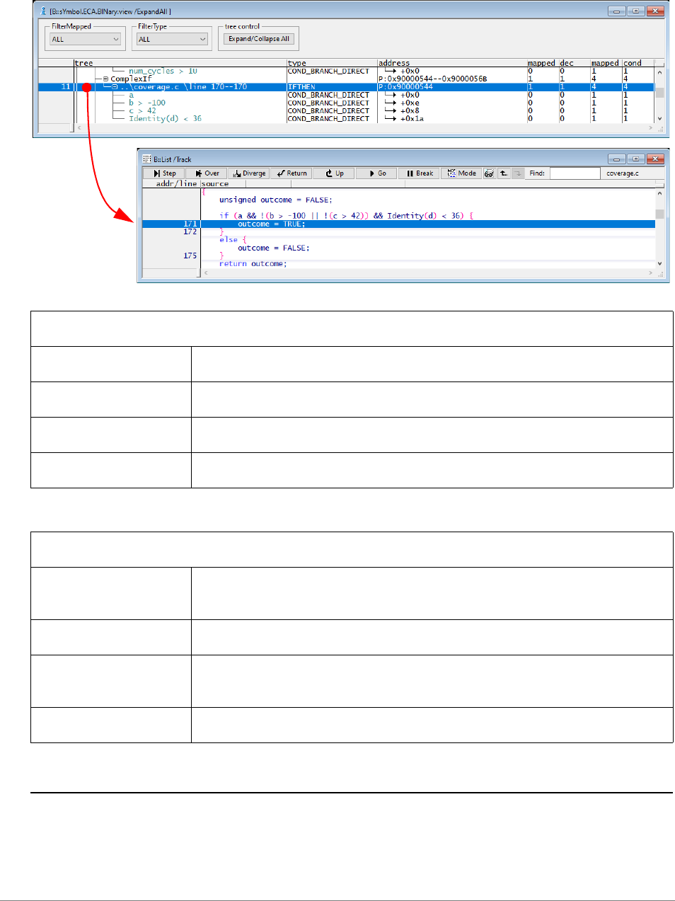
General Commands Reference Guide S | 156
©
1989-2024 Lauterbach
If a List /Track window is open, the source code line selected in the sYmbol.ECA.BINary.view window is
referenced there. The exact type of the decision can be inspected.
See also
■ sYmbol.ECA.BINary.CollapseAll ■ sYmbol.ECA.BINary.ExpandAll
■ sYmbol.ECA.BINary.EXPORT.GAPS ■ sYmbol.ECA.BINary.FilterMapped
■ sYmbol.ECA.BINary.FilterType ■ sYmbol.ECA.BINary.PROCESS
▲ ’Build Process’ in ’Application Note for Trace-Based Code Coverage’
Columns
mapped dec Number of mapped decisions.
dec Overall number of decisions.
mapped cond Mapped conditions.
cond Overall number of conditions.
Options
FilterMapped Filter display by the mapping state, see command
sYmbol.ECA.BINary.FilterMapped.
FilterType Filter display by types, see command sYmbol.ECA.BINary.FilterType.
ExpandAll Open window with all trees expanded. See also command
sYmbol.ECA.BINary.ExpandAll.
StripPATH Overall number of conditions.

General Commands Reference Guide S | 157
©
1989-2024 Lauterbach
sYmbol.ECA.Delete Delete loaded ECA data
Deletes all loaded ECA data and clears the sYmbol.ECA.List window.
See also
■ sYmbol.ECA
sYmbol.ECA.Init Clear gathered ECA data
[build 142398 - DVD 02/2022]
Clears data gathered by sYmbol.ECA commands.
See also
■ sYmbol.ECA
sYmbol.ECA.List List ECA file overview
[Columns] [Toolbar] [Example]
Lists details about the loaded .eca files.
The option /ERRORS advises TRACE32 PowerView to only display the .eca files that were loaded with an
error.
Format: sYmbol.ECA.Delete
Format: sYmbol.ECA.Init
Format: sYmbol.ECA.List [/ERRORS]

General Commands Reference Guide S | 158
©
1989-2024 Lauterbach
Description of Columns in the sYmbol.ECA.List Window
source List of all source files from the TRACE32 symbol database.
The source file names are part of the debug information loaded with the
program.
program Name of the program that includes the object code generated for the
source file.
eca Name of the loaded .eca file.
directory Directory containing the source file and the loaded .eca file.
size Size of the loaded .eca file in bytes.
signature Checksum signature of the loaded .eca file as a hex number.
state The state loaded indicates that the ECA file was loaded successfully.
The state error indicates one of the following:
• .eca file not found.
• .eca file contains invalid data.
The state n/a indicates that TRACE32 does not support .eca files
for the file type. E.g. no .eca data are supported for .asm files.
A state column => loaded: Double-clicking the row opens the ECA file in the TRACE32 EDIT window.
The ECA file opens in an external editor if you have configured one with the SETUP.EDITEXT
command.
B state column => (empty): Double-clicking a row loads the ECA file, if available.
C Check box allows to set the LENient option for loading operations.
C
A
B

General Commands Reference Guide S | 159
©
1989-2024 Lauterbach
Description of Toolbar Buttons in the sYmbol.ECA.List Window
Example: This script loads the .eca data for the module \coverage.
See also
■ sYmbol.ECA
Clear Deletes all previously loaded ECA data and clears the sYmbol.ECA.List
window.
Touch all Loads the .eca file for all source files.
(command sYmbol.ECA.LOADALL /SkipErrors)
Search Path Lists the search paths specified for the source files
(command sYmbol.SourcePATH.List). TRACE32 expects the .eca files in
the same directory as their source files.
ECA Files… Displays full sYmbol.ECA.List window. The button is only active in the
sYmbol.ECA.List /ERRORS window.
Errors… Opens the sYmbol.ECA.List /ERRORS window, displaying only .eca files
tagged with error.
;defines directory as base for relative source paths
sYmbol.SourcePATH.SetBaseDir "J:/user1/projects/sources"
;load program
Data.LOAD.Elf "coverage.elf" /RelPath
;load ECA file for the module \coverage
sYmbol.ECA.LOAD \coverage
sYmbol.ECA.List

General Commands Reference Guide S | 160
©
1989-2024 Lauterbach
sYmbol.ECA.LOAD Load a single ECA file
Loads the ECA data pertaining to the specified <module>.
The sYmbol.List.Module command lists all modules from the TRACE32 symbol database.
The column source shows the name of the corresponding source file.
After the source file is loaded, the column file in the sYmbol.List.SOURCE window shows the full source
path.
TRACE32 searches for the .eca file under this source path.
An error message is displayed when the .eca file is not found or contains invalid data.
See also
■ sYmbol.ECA
▲ ’Release Information’ in ’Legacy Release History’
Format: sYmbol.ECA.LOAD <module> [/<option>]
<option>: SkipErrors | LENient | SetBaseDir
SkipErrors Ensures that warnings are issued instead of error messages. For scripts,
error messages cause the script to stop. Warnings keep the script running.
LENient Allows loading of ECA files with minor errors as invalid file version or
checksum mismatch.
SetBaseDir Forces the search of matching ECA files relative to the specified base
directory.
;load ECA file for the module \coverage
sYmbol.ECA.LOAD \coverage

General Commands Reference Guide S | 161
©
1989-2024 Lauterbach
sYmbol.ECA.LOADALL Load all ECA files
Loads the ECA files for all modules listed in the TRACE32 symbol database.
Example: This script shows how to load all ECA data for the program my_demo.elf.
See also
■ sYmbol.ECA
▲ ’Release Information’ in ’Legacy Release History’
Format: sYmbol.ECA.LOADALL [/<option>]
<option>: SkipErrors | LENient | SetBaseDir
SkipErrors Ensures that warnings are issued instead of error messages. For scripts,
error messages cause the script to stop. Warnings keep the script running.
LENient Allows loading of ECA files with minor errors as invalid file version or
checksum mismatch.
SetBaseDir Forces the search of matching ECA files relative to the specified base
directory.
;load the elf file
Data.LOAD.elf my_demo.elf
;load ECA data for all modules
sYmbol.ECA.LOADALL /SkipErrors

General Commands Reference Guide S | 162
©
1989-2024 Lauterbach
sYmbol.FILTER.ADD.SOURCE Add source files to filter
Several source files are combined under a filter name. The filter can then be used in commands as a
representative of these source files. The syntax of the pathname is oriented towards the source column in
the sYmbol.Browse.SOURCE window.
sYmbol.FILTER.ADD.sYmbol Add symbols to filter
Several symbols are combined under a filter name. The filter can then be used in commands as a
representative of the symbols.
Format: sYmbol.FILTER.ADD.SOURCE <filter_name> <list_of_sources>
<list_of_
sources>
<source0> [<source1> …<source9>]
sYmbol.Browse.SOURCE
sYmbol.FILTER.ADD.SOURCE jd_files \
\"D:/work/demo/mpc5xxx/mpc5646c_jpeg/jdapistd.c" \
\"D:/work/demo/mpc5xxx/mpc5646c_jpeg/jdcolor.c" \
\"D:/work/demo/mpc5xxx/mpc5646c_jpeg/jdmainct.c"
COVerage.ListFunc.preset jd_files
; Add a further source file
sYmbol.FILTER.ADD.SOURCE jd_files \
\"D:/work/demo/mpc5xxx/mpc5646c_jpeg/jdhuff.c"
Format: sYmbol.FILTER.ADD.sYmbol <filter_name> <list_of_symbols>
<list_of_
symbols>
<symbol0> [<symbol1> …<symbol9>]

General Commands Reference Guide S | 163
©
1989-2024 Lauterbach
The example below combines modules to a filter.
sYmbol.FILTER.Delete Delete filter
Delete specified filter.
sYmbol.Browse.Module
sYmbol.FILTER.ADD.sYmbol jd_modules \jdcolor \jdmarker \jdtrans
COVerage.ListFunc.preset jd_modules
sYmbol.FILTER.ADD.sYmbol jd_modules \jdsample
Format: sYmbol.FILTER.Delete <filter_name>
General Commands Reference Guide S | 164
©
1989-2024 Lauterbach
sYmbol.ForEach Symbol wildcard command
Executes a PRACTICE command for each symbol matching the specified name and type patterns.
Examples:
For more examples on wildcards, see command sYmbol.name.
See also
■ sYmbol ❏ sYmbol.MATCHES()
Format: sYmbol.ForEach "<cmd>" [<name_pattern> [<type_pattern>]]
<cmd> The command to be executed has to be specified with quotation marks. It
may contain the characters '*' or '?' as placeholders that are replaced by the
complete name of a matching symbol.
<name_pattern>
<type_pattern>
The patterns are case-insensitive. Therefore lower and upper case
characters are not distinguished. The following wildcards can be used in
pattern expressions:
'*' Matches any string, including empty strings.
For the <type_pattern>, only symbols with HLL type information match.
'?' Matches one (non-empty) character.
'"' Can be used to input special characters like '*' or '?'
sYmbol.ForEach "Break.Set" *func* ; will execute the command
; Break.Set <symbol>
; for all symbols containing
;'func'
sYmbol.ForEach
"Break.Set Var.END(""*"") /Charly" * *
; execute the command
; Break.Set
;Var.END(<symbol>) /Charly
; which sets a “Charly :
; breakpoint” to the
; last address of each HLL
;function or variable

General Commands Reference Guide S | 165
©
1989-2024 Lauterbach
sYmbol.INFO Display detailed information about debug symbol
Displays symbolic address, location, scope and layout of the specified debug <symbol>. If an
<address> is specified, the details about the debug symbol located at <address> are displayed.
The option /Track enables the address tracking. See example 2.
Example 1:
Format: sYmbol.INFO <symbol> | <address> [/Track]
sYmbol.INFO func9 ; display detailed debug information for
; the function func9

General Commands Reference Guide S | 166
©
1989-2024 Lauterbach
Example 2:
sYmbol.INFO , /Track ; display a sYmbol.INFO window with address
; tracking enabled
; you have to use a ",", if you do not want
; to specify the <symbol> parameter
Data.dump 0x40004000 ; display a hex dump starting at address
; 0x40004000
; address tracking works as follows:
; as soon as you select an address in the Data.dump window, details about
; the symbol located at selected address are displayed

General Commands Reference Guide S | 167
©
1989-2024 Lauterbach
See also
■ sYmbol ■ sYmbol.Browse.name ■ sYmbol.STATE ■ Data.dump
■ MMU.INFO ■ Var.INFO
▲ ’The Symbol Database’ in ’Training Source Level Debugging’
List.auto ; Analogous, if a line is selected in the
; Source Listing all the details about the
; related function are displayed


General Commands Reference Guide S | 169
©
1989-2024 Lauterbach
sYmbol.List Display list of all symbols
Displays the sYmbol.List window with a list of all symbols. The list is ordered by the symbols’ addresses
and scrolled so that <address> is shown at the top of the window.
The <address> can be entered as a literal (e.g. P:0xFC004AB) or using a symbol path (e.g.
\\sieve\page1\main). When using wildcards, the symbol path needs to evaluate to a single symbol.
See also
■ sYmbol.List.ATTRibute ■ sYmbol.List.BUILTIN ■ sYmbol.List.ColorDef ■ sYmbol.List.Enum
■ sYmbol.List.FRAME ■ sYmbol.List.Function ■ sYmbol.List.IMPORT ■ sYmbol.List.InlineBlock
■ sYmbol.List.InlineFunction ■ sYmbol.List.LINE ■ sYmbol.List.Local ■ sYmbol.List.MACRO
■ sYmbol.List.MAP ■ sYmbol.List.Module ■ sYmbol.List.PATCH ■ sYmbol.List.Program
■ sYmbol.List.REFerence ■ sYmbol.List.SECtion ■ sYmbol.List.SOURCE ■ sYmbol.List.SourceFunction
■ sYmbol.List.SOURCETREE ■ sYmbol.List.STACK ■ sYmbol.List.Static ■ sYmbol.List.TREE
■ sYmbol.List.Type ■ sYmbol ■ sYmbol.STATE
sYmbol.List.ATTRibute Display memory attributes
Displays memory attributes. Memory attributes can classify the code or execution model at a specific
address. This information is highly compiler dependent.
See also
■ sYmbol.List
sYmbol.List.BUILTIN List built-in data types
Lists all built-in data types of the used programming language.
See also
■ sYmbol.List
Format: sYmbol.List [<address>]
Format: sYmbol.List.ATTRibute [<address>]
Format: sYmbol.List.BUILTIN

General Commands Reference Guide S | 170
©
1989-2024 Lauterbach
sYmbol.List.ColorDef List the keyword color definitions
Lists the color definition for the keywords of the HLL code displayed in the Data.List window (if, else,
while, etc.). The class column in the sYmbol.ListColorDef window shows the currently assigned
formatting class (= style in a word processing application such as OpenOffice.Org Writer).
By default, the keywords are assigned to the formatting class 1, and its default color is blue.
By assigning keywords to class 2 or 3, you can format keywords green or purple. If you want to pick another
color for the classes 2 and 3, then click the change button in the SETUP.COLOR window.
Example 1: This script shows how to change the color of the for keyword. To try this script, copy it to a
test.cmm file, and then step through it in TRACE32 (See “How to...”).
Example 2: A PRACTICE script that adds more keywords to the sYmbol.List.ColorDef window is included
in your TRACE32 installation. To access the script, run this command:
B::CD.PSTEP ~~/demo/practice/colors/syntaxcolor.cmm
See also
■ sYmbol.List ■ sYmbol.ColorDef ■ SETUP.COLOR
▲ ’PowerView - Screen Display’ in ’PowerView User’s Guide’
Format: sYmbol.List.ColorDef
sYmbol.List.ColorDef ;Display the keywords, their colors, and
;the classes to which the keywords are assigned
SETUP.COLOR ;Display the current color settings
sYmbol.ColorDef "for" 2. ;Assign the keyword 'for' to class 2 =>
;'for' turns green
sYmbol.ColorDef "for" 3. ;Assign the keyword 'for' to class 3 =>
;'for' turns purple
SETUP.COLOR 39. 255. 128. 0. ;Change the color of class 3 to orange
SETUP.COLOR 39. ;Restore the default color of class 3 again
sYmbol.ColorDef "for" 1. ;Apply class 1 to the 'for' keyword again
Change keyword color.


General Commands Reference Guide S | 172
©
1989-2024 Lauterbach
sYmbol.List.FRAME Display frames
Lists the location and further related information about the frames. In the sYmbol.List.FRAME window,
each entry tells the debugger for a certain program range where the registers are saved, e.g. relative to the
current stack pointer (SP).
Description of Columns in the sYmbol.List.FRAME Window
Description of Values in the “rules” Column
See also
■ sYmbol.List ■ Frame
Format: sYmbol.List.FRAME [<address>]
address Address range of a single frame
rules Rules used by TRACE32 PowerView to recover the previous stack
frames.
RET Location of the return value, e.g. a register
R0 to R14 Register names (architecture-specific)
CFA Canonical frame address
<register>:used Registers which cannot be recovered
<register>:- Registers with valid content
*CFA-<offset>
or
*CFA+<offset>
Address where the register content can be recovered from,
e.g. *CFA-0x4

General Commands Reference Guide S | 173
©
1989-2024 Lauterbach
sYmbol.List.Function Display functions
Lists the location and further related information about the loaded functions.
See also
■ sYmbol.List
sYmbol.List.IMPORT List imported symbols
Lists the symbols that are loaded by imported DLLs (required e.g. for Symbian or Windows CE).
See also
■ sYmbol.List
Format: sYmbol.List.Function [<range> | <address>]
Format: sYmbol.List.IMPORT

General Commands Reference Guide S | 174
©
1989-2024 Lauterbach
sYmbol.List.InlineBlock List inlined code blocks
When compiling with optimization the compiler may insert functions or parts of a function directly
instead of adding a call to the function. This command lists all parts of the code where function parts
have been inlined by the compiler.
See also
■ sYmbol.List
sYmbol.List.InlineFunction List inlined functions
Lists the location and further related information about the loaded inline functions.
See also
■ sYmbol.List
Format: sYmbol.List.InlineBlock
Format: sYmbol.List.InlineFunction


General Commands Reference Guide S | 176
©
1989-2024 Lauterbach
sYmbol.List.Local Display local symbols
Displays all symbols local to functions and blocks.
See also
■ sYmbol.List
sYmbol.List.MACRO List all C macros
List all C macros. C macros can either be loaded with Data.LOAD <file> /MACRO or they can be created
with the command sYmbol.Create.MACRO.
See also
■ sYmbol.List
Format: sYmbol.List.Local [<range> | <address>]
Format: sYmbol.List.MACRO

General Commands Reference Guide S | 177
©
1989-2024 Lauterbach
sYmbol.List.MAP Display memory load map
Displays address ranges where code was saved during download and the order in which the code was
saved. Can be used to find out “where the code has gone”.
Example:
See also
■ sYmbol.List ❏ sYmbol.List.MAP.COUNT() ❏ sYmbol.List.MAP.RANGE()
sYmbol.List.Module Display modules
Displays information about the loaded models, e.g. the location or the loaded source file.
See also
■ sYmbol.List
Format: sYmbol.List.MAP [<address>]
;<your_code>
SYStem.Up ;connect to target
Data.LOAD.Elf sieve_flash_thumb_ii_v7m.elf ;load application to target
sYmbol.List.MAP ;let's find out
;"where the code has gone"
A The loaded *.elf file contains two section, and the code has been loaded to these two address
ranges.
Format: sYmbol.List.Module [<address>]
A

General Commands Reference Guide S | 178
©
1989-2024 Lauterbach
sYmbol.List.PATCH Display STF-symbol information
Is a alias for sYmbol.PATCH.List.
See also
■ sYmbol.List
sYmbol.List.Program Display programs
Displays the location and further related information about the loaded programs.
See also
■ sYmbol.List ❏ sYmbol.LIST.PROGRAM()
Format: sYmbol.List.PATCH [<address>]
Format: sYmbol.List.Program


General Commands Reference Guide S | 180
©
1989-2024 Lauterbach
sYmbol.List.SECtion Display physical sections
Opens the sYmbol.List.SECtion window, displaying the logical address ranges, section names, and
access rights for the sections. Physical address ranges are also displayed, provided the file type contains
any.
Description of Columns in the sYmbol.List.SECtions Window
See also
■ sYmbol.List ❏ sYmbol.SECADDRESS() ❏ sYmbol.SECEND() ❏ sYmbol.SECNAME()
❏ sYmbol.SECPRANGE() ❏ sYmbol.SECRANGE()
Format: sYmbol.List.SECtion [<address>]
address Logical address range of a section.
path\section Section names in source files.
acc Access rights:
• R: Read access
• W: Write access
• X: Section can execute code
load
• L: Section is loaded by the debugger.
• 0: Section is set to zero by the debugger.
physical Physical address range of a section - only for certain file types and
architectures.
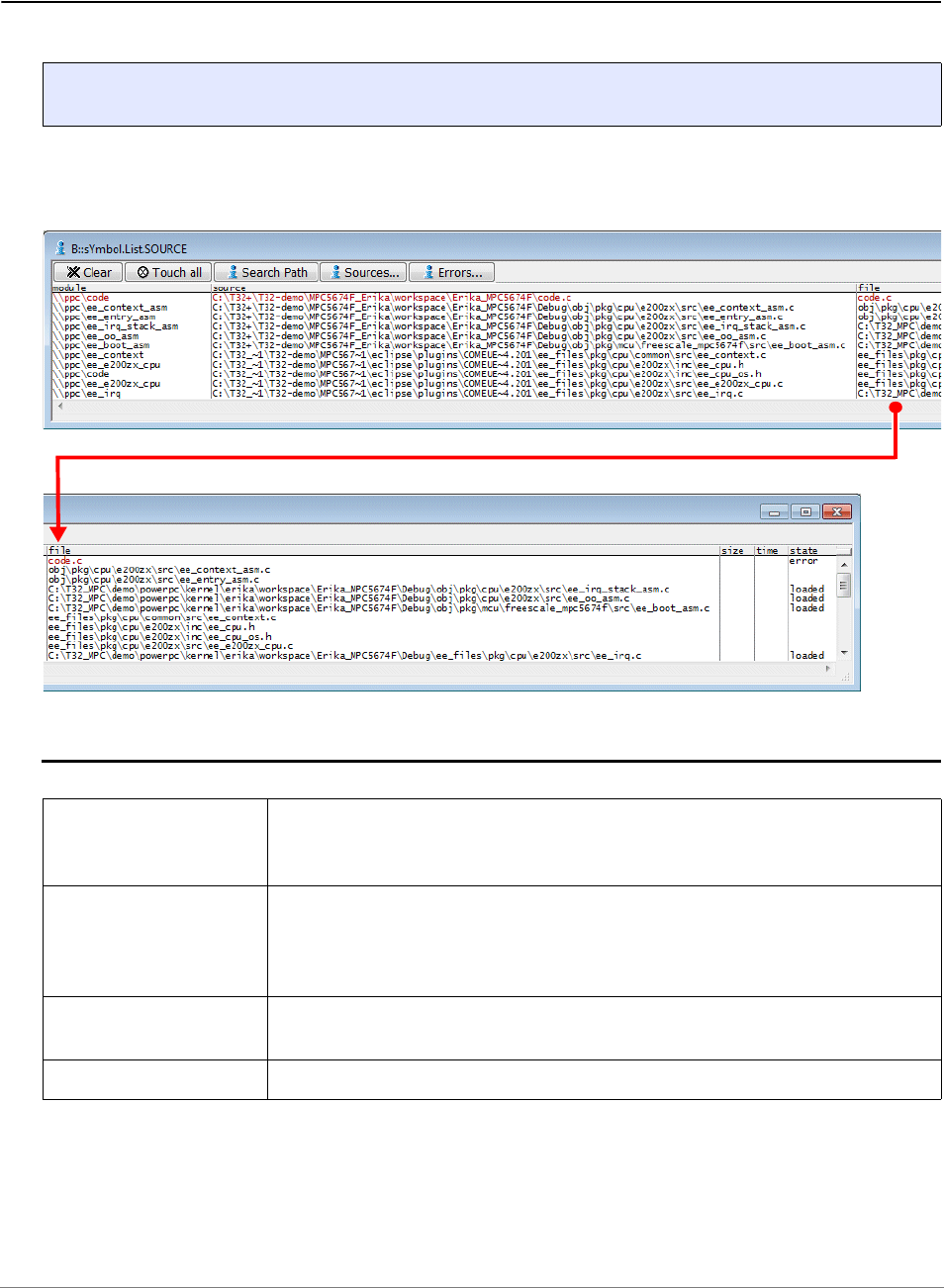
General Commands Reference Guide S | 181
©
1989-2024 Lauterbach
sYmbol.List.SOURCE Display source file names
[Example]
If a files with debug information is loaded (Data.LOAD.<file_format>), this file also provides the paths for
the HLL (C/C++/JAVA etc.) source files. The command sYmbol.List.SOURCE lists the file names and
paths in the source column.
Description of Toolbar Buttons in the sYmbol.List.SOURCE Window
Format: sYmbol.List.SOURCE [/ERRORS]
Clear Invalidates the state column for all source files and invalidates the search
results displayed in the file column
(command sYmbol.SourceRELOAD).
Touch All By default an HLL source file is only loaded by TRACE32 when the contents
of the HLL source file is required during debugging. This button advises
TRACE32 to load all source files
(command sYmbol.SourceLOAD).
Search Path Displays details on source search paths
(command sYmbol.SourcePATH.List).
Errors Display only modules tagged with error in the state column.

General Commands Reference Guide S | 182
©
1989-2024 Lauterbach
Description of Columns in the sYmbol.List.SOURCE Window
Example:
Resolve Path in the Source context menu opens a dialog where you can choose the correct path for the
selected module/source. TRACE32 adds the result to the source search paths. The result can be inspected
via the sYmbol.SourcePATH.List command. The procedure is as follows:
• Absolute paths are fixed with the help of the command sYmbol.SourcePATH.Translate.
• Relative paths are fixed with the help of the command sYmbol.SourcePATH.SetBaseDir.
See also
■ sYmbol.List ■ sYmbol.ECA ❏ sYmbol.LIST.SOURCE()
▲ ’Release Information’ in ’Legacy Release History’
module Path of the compiled file as it is maintained by TRACE32.
source Source path for C/C++/JAVA source file after the completion of the
Data.LOAD.<file_format> command.
file Source path from which the C/C++/JAVA source file was actually loaded.
Required adjustments of the source path can be performed with the help
of the sYmbol.SourcePATH command group.
size Size information as provided by the loaded file.
time Time information as provided by the loaded file.
state The state loaded indicates that the C/C++/JAVA source file was loaded
successfully.
The state error indicates that the C/C++/JAVA source file could not be
loaded. Modules tagged with error are printed in red.
sYmbol.List.SOURCE /ERRORS // Advise TRACE32 PowerView to display
// only modules tagged with error.


General Commands Reference Guide S | 184
©
1989-2024 Lauterbach
sYmbol.List.SOURCETREE Display source files hierarchy
Displays the hierarchy of the source files in a tree structure.
See also
■ sYmbol.List
sYmbol.List.STACK Display virtual stack
Displays information about virtual stack pointers. This information is highly compiler dependent.
See also
■ sYmbol.List
Format: sYmbol.List.SOURCETREE
Format: sYmbol.List.STACK [<address>]

General Commands Reference Guide S | 185
©
1989-2024 Lauterbach
sYmbol.List.Static Display static symbols
Displays all symbols with a fixed address.
See also
■ sYmbol.List
sYmbol.List.TREE Display symbols in tree form
Displays modules, symbols, and variables in a tree structure.
See also
■ sYmbol.List
Format: sYmbol.List.Static [<range> | <address>]
Format: sYmbol.List.TREE

General Commands Reference Guide S | 187
©
1989-2024 Lauterbach
sYmbol.LSTLOAD Load assembler source file
Using the sYmbol.LSTLOAD command group, you can load various formats of assembler list files for
source text debugging on assembler level.
See also
■ sYmbol.LSTLOAD.GHILLS ■ sYmbol.LSTLOAD.HPASM
■ sYmbol.LSTLOAD.IAR ■ sYmbol.LSTLOAD.INT68K
■ sYmbol.LSTLOAD.INTEL ■ sYmbol.LSTLOAD.INTEL2
■ sYmbol.LSTLOAD.KEIL ■ sYmbol.LSTLOAD.MicroWare
■ sYmbol.LSTLOAD.MRI68K ■ sYmbol.LSTLOAD.OAK
■ sYmbol
sYmbol.LSTLOAD.GHILLS Load GHILLS assembler source file
Loading of a GHILLS assembler list file for source text debugging on assembler level. If the base address of
the module doesn’t fit, the base address will be given as an argument.
See also
■ sYmbol.LSTLOAD
sYmbol.LSTLOAD.HPASM Load HP assembler source file
Loading of an HP assembler list file for source text debugging on assembler level. If the base address of the
module doesn't fit, the base address will be given as an argument. If a program name is given, the module
entry will be generated from the file name of the list file. The different commands load different HP assembler
list file formats.
The debugging can be controlled by the following assembler comments:
; T32-ORG
To mark lines including ORG statements.
Format: sYmbol.LSTLOAD.GHILLS <module>|<program> <file> [<base_address>]
Format: sYmbol.LSTLOAD.HPASM <module>|<program> <file> [<base>]
Format: sYmbol.LSTLOAD.HPASM2 <module>|<program> <file> [<base>]

General Commands Reference Guide S | 188
©
1989-2024 Lauterbach
; T32-OFF
To switch of the source text debugging. The debugging must be switched of for lines containing data
statements or definitions (i.e. lines which address column not containing a program address). Include files,
which shall not be displayed, must be switched off also.
;T32-ON
Reactivation of the debugging function.
See also
■ sYmbol.LSTLOAD
NOTE: The source line numbers will not match in this case, as the relation to the original
source is lost.
Data.LOAD.HP sps
sYmbol.LSTLOAD.HPASM \SPS1 sps1.lst
sYmbol.LSTLOAD.HPASM \SPS2 sps2.lst
; load the module and symbols
; load the source lines for
; module 1
; load the source lines for
; module 2

General Commands Reference Guide S | 189
©
1989-2024 Lauterbach
sYmbol.LSTLOAD.IAR Load IAR assembler source file
Loading of a IAR assembler list file for source text debugging on assembler level. If the base address of the
module doesn't fit, the base address will be given as an argument.
The first comment line of the file (beginning with '*') must start in the first column of the source text! The
debugging can be controlled by the following assembler comments:
*T32-ORG
To mark lines including ORG statements.
*T32-OFF
To switch of the source text debugging. The debugging must be switched of for lines containing data
statements or definitions (i.e. lines which address column not containing a program address). Include files,
which shall not be displayed, must be switched off also.
*T32-ON
Reactivation of the debugging function.
See also
■ sYmbol.LSTLOAD
Format: sYmbol.LSTLOAD.IAR <module>|<program> <file> [<base_address>]
NOTE: The source line numbers will not match in this case, as the relation to the original
source is lost.

General Commands Reference Guide S | 190
©
1989-2024 Lauterbach
sYmbol.LSTLOAD.INT68K Load Intermetrics assembler source file
Loading of a Intermetrics assembler list file for source text debugging on assembler level. If the base
address of the module doesn't fit, the base address will be given as an argument.
The debugging can be controlled by the following assembler comments:
*T32-ORG
To mark lines including ORG statements.
*T32-OFF
To switch of the source text debugging. The debugging must be switched of for lines containing data
statements or definitions (i.e. lines which address column not containing a program address).
*T32-ON
Reactivation of the debugging function.
See also
■ sYmbol.LSTLOAD
sYmbol.LSTLOAD.INTEL Load INTEL assembler source file
Loading of a INTEL assembler list file for source text debugging on assembler level. If the base address of
the module doesn’t fit, the base address will be given as an argument.
See also
■ sYmbol.LSTLOAD
Format: sYmbol.LSTLOAD.INT68K <module>|<program> <file> [<base_address>]
Format: sYmbol.LSTLOAD.INTEL <module>|<program> <file> [<base_address>]

General Commands Reference Guide S | 191
©
1989-2024 Lauterbach
sYmbol.LSTLOAD.INTEL2 Load INTEL assembler source file
Loading of a INTEL multi-segment assembler list file for source text debugging on assembler level. If the
base address of the module doesn’t fit, the base address will be given as an argument. This
See also
■ sYmbol.LSTLOAD
sYmbol.LSTLOAD.KEIL Load Keil assembler source file
Loading of an KEIL (8051) assembler list file for source text debugging on assembler level. The base
address is optional, it is used when the address sections are unknown.
See also
■ sYmbol.LSTLOAD
sYmbol.LSTLOAD.MicroWare Load MICROWARE assembler source file
Loading of a MICROWARE assembler list file for source text debugging on assembler level. If the base
address of the module doesn't fit, the base address will be given as an argument. If a program name is
given, the module entry will be generated from the file name of the list file.
Format: sYmbol.LSTLOAD.INTEL2 <module>|<program> <file> [<base_address>]
Format: sYmbol.LSTLOAD.KEIL <module> <file> [<base>]
Format: sYmbol.LSTLOAD.MicroWare <module>|<program> <file> [<base>]

General Commands Reference Guide S | 192
©
1989-2024 Lauterbach
Example:
See also
■ sYmbol.LSTLOAD
Data.LOAD.ROF sps /MAP
sYmbol.LSTload.mw \\SPS sps1.lst 0x1000
sYmbol.LSTload.MicroWare \\SPS sps2.lst 0x1200
; load the module and
; symbols
; load the source
; lines for module 1
; load the source
; lines for module 2

General Commands Reference Guide S | 193
©
1989-2024 Lauterbach
sYmbol.LSTLOAD.MRI68K Load MICROTEC assembler source file
Loading of a MICROTEC assembler list file for source text debugging on assembler level. If the base
address of the module doesn't fit, the base address will be given as an argument.
The first comment line of the file (beginning with '*') must start in the first column of the source text! The
debugging can be controlled by the following assembler comments:
*T32-ORG
To mark lines including ORG statements.
*T32-OFF
To switch of the source text debugging. The debugging must be switched of for lines containing data
statements or definitions (i.e. lines which address column not containing a program address).
*T32-ON
Reactivation of the debugging function.
See also
■ sYmbol.LSTLOAD
sYmbol.LSTLOAD.OAK Load OAK assembler source file
Loading of a OAK assembler list file for source text debugging on assembler level.
See also
■ sYmbol.LSTLOAD
Format: sYmbol.LSTLOAD.MRI68K <module>|<program> <file> [<base_address>]
Format: sYmbol.LSTLOAD.OAK <module>|<program> <file> [<base>]

General Commands Reference Guide S | 194
©
1989-2024 Lauterbach
sYmbol.MARKER Fine-tune the nested function run-time analysis
The sYmbol.MARKER commands are intended for very advanced users only. The commands are used for
fine-tuning the nesting function run-time analysis, typically in conjunction with the Trace.STATistic.Func
command. Markers can be used to handle special cases for nested trace statistics. Please contact
Lauterbach support before using the sYmbol.MARKER commands.
The sYmbol.MARKER commands let you create markers for symbols, display them in a list window, delete
individual markers, and reset all markers. The following examples are just intended to illustrate these
actions.
Example 1:
Example 2:
See also
■ sYmbol ■ sYmbol.MARKER.Create ■ sYmbol.MARKER.Delete ■ sYmbol.MARKER.List
■ sYmbol.MARKER.RESet ■ sYmbol.MARKER.TOUCH
▲ ’Release Information’ in ’Legacy Release History’
;Display the marker list window
sYmbol.MARKER.List
;Create function entry markers for the functions func1, main
sYmbol.MARKER.Create FENTRY func1
sYmbol.MARKER.Create FENTRY main
;Create function exit markers
sYmbol.MARKER.Create FEXIT sYmbol.EXIT(func1)
sYmbol.MARKER.Create FEXIT sYmbol.EXIT(main)
A Double-click a line to open a List.auto window, displaying the location of a marker. Note that the
marker itself is not visible in the List.auto window.
;Delete an individual function entry marker
sYmbol.MARKER.Delete func1
;Delete an individual function exit marker
sYmbol.MARKER.Delete sYmbol.EXIT(main)
;Delete all markers
sYmbol.MARKER.RESet
A

General Commands Reference Guide S | 195
©
1989-2024 Lauterbach
sYmbol.MARKER.Create Marker for nesting function run-time analysis
Nesting function run-time analysis commands likeTrace.STATistic.Func process the trace information to
reconstruct the function call hierarchy. The focus is put on the transitions between functions. The following
events are of interest:
• Function entries/exits
• Task switches
• Entries/exits of interrupt service routines
• Entries/exits of TRAP handlers
Optimization of the OS and the compiler as well as the technology used for the trace generation may disturb
the reconstruction of the call hierarchy. As a result, nesting function run-time analysis fails. Markers are a
mean to feed TRACE32 with additional information that help to pass blocking points in the analysis.
The command sYmbol.MARKER.List provides a list of all created markers.
Format: sYmbol.MARKER.Create <type> <instruction_address>
sYmbol.CREATE.MARKER (deprecated)
sYmbol.NEW.MARKER (deprecated)
<type>: KENTRY | KEXIT | KBACKDOOR | KBEGIN | KEND | KFROM | KTO |
KLEAVE | FENTRY | KFENTRY | IFENTRY | ILEAVE | FEXIT |
FEXITINIT | FEXITDOUBLE | FEXITCLEANUP | FBACKDOOR | KFBACK-
DOOR | CLEANUP | CLEANUP2 | IGNORE | IGNOREFROM | IGNORETO |
CALL | JUMP | BYJUMP | TASKSWITCH | CORRELATE
sYmbol.MARKER.Create KENTRY os_prologue ; mark the address os_prologue
; as kernel entry point
sYmbol.MARKER.Create KEXIT os_epilogue ; mark the address os_epilogue
; as kernel exit point
sYmbol.MARKER.List ; list all markers

General Commands Reference Guide S | 196
©
1989-2024 Lauterbach
KENTRY/KEXIT/KBACKDOOR Marker
A detailed description of the usage of the markers is given at the command description of
Trace.STATistic.TASKKernel and Trace.STATistic.TASKFunc.
KBEGIN/KEND Marker
Mark <address> as kernel event. These markers work the same way as KENTRY and KEXIT but are
not nested, i.e. a KEND marker closes all previously opened KBEGIN markers.
FENTRY/FEXIT/FBACKDOOR/FEXITDOUBLE/FEXITINT Marker
A detailed description of the usage of the markers is given at the command description of
Trace.STATistic.Func.
sYmbol.MARKER.Create KENTRY os_prologue ; mark the address
; os_prologue
; as kernel entry point
sYmbol.MARKER.Create KEXIT os_epilogue ; mark the address
; os_epilogue
; as kernel exit point
sYmbol.MARKER.List ; list all markers
FENTRY <address> Mark <address> as function entry.
FEXIT <address> Mark <address> as function exit.
FBACKDOOR <address> Mark <address> as function entry. TRACE32 ignores this function
entry in the trace evaluation if a prior function entry was detected.
FEXITDOUBLE <address> Mark <address> as function exit where a function exits two
function levels.
FEXITINT <address> Mark <address> as interrupt exit/return event.

General Commands Reference Guide S | 197
©
1989-2024 Lauterbach
CORRELATE Marker
Purpose: Solve issues of trace export technology.
CORRELATE markers allows to assign read/write accesses to instructions.
If trace information is exported for all executed instructions but only for selected read/write accesses, an
exact assignment of an read/write access to the load/store operation is not possible in most cases. The
read/write access is displayed in the Trace Listing in red before the next exported instruction information
(ptrace).
This behavior may disturb the reconstruction of the call hierarchy in the following case: A task switch occurs
(write access to variable holding the task ID) and then a function is called, but in the Trace Listing the task
switch is displayed after the function call. As a result the function is hooked into the wrong call tree.
More than one CORRELATE marker is possible as long as its address is unique between two ptrace
packets.
In the example below, the write access to the task identifier (TASK.CONFIG(magic)) and all instructions are
exported via a Nexus port (MPC5646).
…
NEXUS.BTM ON
NEXUS.HTM ON
Break.Set TASK.CONFIG(magic) /Write /TraceData
…

General Commands Reference Guide S | 198
©
1989-2024 Lauterbach
For the reconstruction of the call hierarchy and an accurate timing the write access of the task ID has to be
assigned exactly to the corresponding instruction. For this purpose a CORRELATE marker can be used.
IGNORE / IGNOREFROM / IGNORETO / IGNOREALLFUNC
See also
■ sYmbol.MARKER
▲ ’Release Information’ in ’Legacy Release History’
sYmbol.MARKER.Create CORRELATE V:4000105C
IGNORE <address> TRACE32 ignores all instructions with the specified
<address>, for nesting function run-time analysis.
IGNOREFROM <start_address>
IGNORETO <end_address>
TRACE32 ignores all instructions between
<start_address> and <end_address>, for nesting
function run-time analysis.
IGNOREALLFUNC TRACE32 ignores all function entries and all function
exits, for nesting function run-time analysis.
General Commands Reference Guide S | 199
©
1989-2024 Lauterbach
sYmbol.MARKER.Delete Delete a marker
Deletes the specified marker. To delete all markers, use sYmbol.MARKER.RESet.
See also
■ sYmbol.MARKER
sYmbol.MARKER.List Displays the marker list
Opens the sYmbol.MARKER.List window, displaying the list of markers created with
sYmbol.MARKER.Create.
A detailed description of the usage of the markers is given at the command description of
Trace.STATistic.TASKKernel and Trace.STATistic.TASKFunc.
See also
■ sYmbol.MARKER
sYmbol.MARKER.RESet Erase all markers
Removes all markers created with sYmbol.MARKER.Create.
See also
■ sYmbol.MARKER
Format: sYmbol.MARKER.Delete <address>
Format: sYmbol.MARKER.List [<address>]
sYmbol.List.MARKER [<address>] (deprecated)
Format: sYmbol.MARKER.RESet

General Commands Reference Guide S | 200
©
1989-2024 Lauterbach
sYmbol.MARKER.TOUCH Marker post-processing
Default: ON
Enables/disables the re-processing of the function nesting analysis results after sYmbol.MARKER.Create
commands. This command can be used in order to speed up the marker processing in TRACE32 in case a
large number of markers is created.
Example:
See also
■ sYmbol.MARKER
sYmbol.MATCH Symbol search mode
Defines the behavior when a symbol is not unique.
See also
■ sYmbol ■ Data.Find
Format: sYmbol.MARKER.TOUCH [ON | OFF]
sYmbol.MARKER.TOUCH OFF
;<group of sYmbol.MARKER.Create commands>
sYmbol.MARKER.TOUCH ON
Format: sYmbol.MATCH [Exact | Best | Choose]
Exact Refuses any symbols that are not unique. This adjustment is useful for
regression test and automatic batch scripts.
Best Open browser window to choose symbol when there is no best match.
This is the default.
Choose Opens a symbol browser to choose from one of the symbols. This is
useful for choosing between different overloaded methods in C++.


General Commands Reference Guide S | 202
©
1989-2024 Lauterbach
sYmbol.Modify Modify symbols
This command group allows to modify the symbol table or add additional information to existing symbols and
types. See also sYmbol.RELOCate.
See also
■ sYmbol.Modify.Access ■ sYmbol.Modify.ADDRess
■ sYmbol.Modify.AddressToRange ■ sYmbol.Modify.AlienFunction
■ sYmbol.Modify.ATTRibute ■ sYmbol.Modify.CutFunction
■ sYmbol.Modify.NAME ■ sYmbol.Modify.NAMES
■ sYmbol.Modify.RangeToAddress ■ sYmbol.Modify.RangeToFunction
■ sYmbol.Modify.SOURCE ■ sYmbol.Modify.SplitFunction
■ sYmbol.Modify.StaticCOPY ■ sYmbol.Modify.StaticToStack
■ sYmbol.Modify.TYPE ■ sYmbol
▲ ’Release Information’ in ’Legacy Release History’
sYmbol.Modify.Access Modify access of symbols
Modifies the memory access class of symbols. The symbol path limits the modification to special symbols of
a module or a program. If an address range is given, only the symbols in this range will be modified. The
command is useful in combination with the automatic symbol relocation feature, when constants are placed
in ROM.
Examples:
See also
■ sYmbol.Modify.ADDRess ■ sYmbol.Modify.AddressToRange
■ sYmbol.Modify.AlienFunction ■ sYmbol.Modify.ATTRibute
■ sYmbol.Modify ■ sYmbol.Modify.CutFunction
■ sYmbol.Modify.NAME ■ sYmbol.Modify.NAMES
■ sYmbol.Modify.RangeToAddress ■ sYmbol.Modify.RangeToFunction
■ sYmbol.Modify.SOURCE ■ sYmbol.Modify.SplitFunction
■ sYmbol.Modify.StaticCOPY ■ sYmbol.Modify.StaticToStack
■ sYmbol.Modify.TYPE
Format: sYmbol.Modify
Format: sYmbol.Modify.Access <class>: [<symbol_path>|<range>]
sYmbol.Modify.Access d:0x1000--0x1fff ; all symbols in the range get
; the memory access class d:
sYmbol.Modify.Access p:
sYmbol.SECRANGE(const)
; all symbols in the 'const'
; section get the memory
; access class p:

General Commands Reference Guide S | 203
©
1989-2024 Lauterbach
sYmbol.Modify.ADDRess Modify address of symbols
Modifies the start address or address range of a symbol, module, program or function.
Example:
See also
■ sYmbol.Modify.Access ■ sYmbol.Modify.AddressToRange
■ sYmbol.Modify.AlienFunction ■ sYmbol.Modify.ATTRibute
■ sYmbol.Modify ■ sYmbol.Modify.CutFunction
■ sYmbol.Modify.NAME ■ sYmbol.Modify.NAMES
■ sYmbol.Modify.RangeToAddress ■ sYmbol.Modify.RangeToFunction
■ sYmbol.Modify.SOURCE ■ sYmbol.Modify.SplitFunction
■ sYmbol.Modify.StaticCOPY ■ sYmbol.Modify.StaticToStack
■ sYmbol.Modify.TYPE
sYmbol.Modify.AddressToRange Modify address of symbols
Extends a single address label into a symbol with an address range. The address range starts at the symbol
address and ends at the address of the next symbol minus 1. This command is the opposite of
sYmbol.Modify.RangeToAddress.
Example:
See also
■ sYmbol.Modify.Access ■ sYmbol.Modify.ADDRess ■ sYmbol.Modify ■ sYmbol.Modify.SOURCE
Format: sYmbol.Modify.ADDRess <symbol> <address>|<range>
; assign new range to module
sYmbol.Modify.ADDRess \mymodule 0x1000--0x1fff
Format: sYmbol.Modify.AddressToRange <symbol> |<address>
sYmbol.Modify.AddressToRange mylabel

General Commands Reference Guide S | 204
©
1989-2024 Lauterbach
sYmbol.Modify.AlienFunction Disable frame info for a function
Disables frame information for a selected function.
See also
■ sYmbol.Modify.Access ■ sYmbol.Modify.ADDRess ■ sYmbol.Modify ■ sYmbol.Modify.SOURCE
sYmbol.Modify.ATTRibute Modify memory attribute
Modifies the attribute of the given memory range
Example:
See also
■ sYmbol.Modify.Access ■ sYmbol.Modify.ADDRess ■ sYmbol.Modify ■ sYmbol.Modify.SOURCE
sYmbol.Modify.CutFunction Reduce function address information
Reduces the address range information for the defined functions to a single address. This command is used
only in very special cases.
Format: sYmbol.Modify.AlienFunction <symbol> |<range>
Format: sYmbol.Modify.ATTRibute <attribute> <symbol>|<range>
; change the memory attribute for the range 0x400--0x4FF to DATA
sYmbol.Modify.ATTRibute DATA 0x400--0x4FF
Format: sYmbol.Modify.CutFunction <range> | <address>

General Commands Reference Guide S | 205
©
1989-2024 Lauterbach
Example:
See also
■ sYmbol.Modify ■ sYmbol.Modify.Access ■ sYmbol.Modify.ADDRess ■ sYmbol.Modify.SOURCE
▲ ’Release Information’ in ’Legacy Release History’
sYmbol.Modify.NAME Rename symbol
Renames symbol. If multiple symbols with the given name are available, an error “ambiguous symbol” is
returned. Use in this case sYmbol.Modify.NAMES.
Example:
See also
■ sYmbol.Modify ■ sYmbol.Modify.Access ■ sYmbol.Modify.ADDRess ■ sYmbol.Modify.SOURCE
sYmbol.Modify.NAMES Rename symbols
Renames all symbols having the name <symbol_name>, except for function locals.
If you need to rename a lot of symbols, consider using sYmbol.DEOBFUSCATE as it will be much faster.
See also
■ sYmbol.Modify ■ sYmbol.Modify.Access ■ sYmbol.Modify.ADDRess ■ sYmbol.Modify.SOURCE
■ sYmbol.DEOBFUSCATE
sYmbol.List.Function
sYmbol.Modify.CutFunction 0x104c++0xff
Format: sYmbol.Modify.NAME <symbol_name> <new_name>
; renames ‘vtriplearray’ to ‘tt’
sYmbol.Modify.NAME vtripplearray tt
Format: sYmbol.Modify.NAMES <symbol_name> <new_name>

General Commands Reference Guide S | 206
©
1989-2024 Lauterbach
sYmbol.Modify.RangeToAddress Modify address of symbols
Changes an symbol with an address range into a single address label. This command is the opposite of
sYmbol.Modify.AddressToRange.
See also
■ sYmbol.Modify ■ sYmbol.Modify.Access ■ sYmbol.Modify.ADDRess ■ sYmbol.Modify.SOURCE
sYmbol.Modify.RangeToFunction Modify address range into function
Modifies address range into function.
Example: assembly functions are often represented in the debugging information by the compiler as a
single address label. As a consequence, these assembly functions won’t be included in the function run-time
analysis windows. The commands sYmbol.Modify.AddressToRange and
sYmbol.Modify.RangeToFunction can be used together to change these single address labels into
functions.
See also
■ sYmbol.Modify ■ sYmbol.Modify.Access ■ sYmbol.Modify.ADDRess ■ sYmbol.Modify.SOURCE
sYmbol.Modify.SOURCE Define source file
Defines the source file name for a given module. The command can be used when the names or directories
of source files have been changed after compilation.
Format: sYmbol.Modify.AddressToRange <symbol> |<address>
Format: sYmbol.Modify.RangeToFunction <symbol> |<range>
sYmbol.Modify.AddressToRange _divsi3
sYmbol.Modify.RangeToFunction _divsi3
Format: sYmbol.Modify.SOURCE <module> <file>
General Commands Reference Guide S | 207
©
1989-2024 Lauterbach
Example:
See also
■ sYmbol.Modify.SplitFunction ■ sYmbol.Modify.StaticCOPY
■ sYmbol.Modify.StaticToStack ■ sYmbol.Modify
■ sYmbol.Modify.Access ■ sYmbol.Modify.ADDRess
■ sYmbol.Modify.AddressToRange ■ sYmbol.Modify.AlienFunction
■ sYmbol.Modify.ATTRibute ■ sYmbol.Modify.CutFunction
■ sYmbol.Modify.NAME ■ sYmbol.Modify.NAMES
■ sYmbol.Modify.RangeToAddress ■ sYmbol.Modify.RangeToFunction
■ sYmbol.Modify.TYPE
sYmbol.Modify.SplitFunction Split function
Makes two functions out of one function. Takes a label inside the function as a parameter. The second
function starts at this label and has the name of the label.
See also
■ sYmbol.Modify.SOURCE ■ sYmbol.Modify ■ sYmbol.Modify.Access ■ sYmbol.Modify.ADDRess
sYmbol.Modify.StaticCOPY Create static copy of local stack variables
Creates static copy of local stack variables.
See also
■ sYmbol.Modify.SOURCE ■ sYmbol.Modify ■ sYmbol.Modify.Access ■ sYmbol.Modify.ADDRess
; use source file mod2.c for module 'mod1'
sYmbol.Modify.SOURCE \mod1 ..\src\mod2.c
Format: sYmbol.Modify.SplitFunction <label>
Format: sYmbol.Modify.StaticCOPY <module> <address> <address> [<reg>]

General Commands Reference Guide S | 208
©
1989-2024 Lauterbach
sYmbol.Modify.StaticToStack Change static variables
Changes static variables into global stack variables.
See also
■ sYmbol.Modify.SOURCE ■ sYmbol.Modify ■ sYmbol.Modify.Access ■ sYmbol.Modify.ADDRess
sYmbol.Modify.TYPE Modify type of symbols
Changes the symbol type.
See also
■ sYmbol.Modify ■ sYmbol.Modify.Access ■ sYmbol.Modify.ADDRess ■ sYmbol.Modify.SOURCE
▲ ’Release Information’ in ’Legacy Release History’
Format: sYmbol.Modify.StaticToStack <reg> <address> [<symbol | address range>]
Format: sYmbol.Modify.TYPE <symbol> <type>
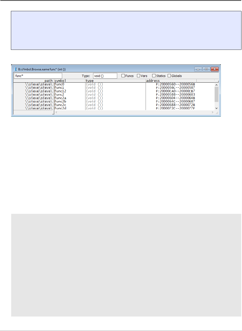
General Commands Reference Guide S | 209
©
1989-2024 Lauterbach
sYmbol.name Display symbols
Displays symbols sorted alphabetically.
Lower and upper case characters are not distinguished. For mangled C++ symbols the search order is
based on the function signatures. A complex search function is implemented to find symbol name very fast,
if the complete name will be not known. The search patterns are:
If the wildcard '*' is defined for the type_pattern, only symbols with HLL type information are extracted. The
C++ demangler for the symbols is used, if the pattern contains the characters '(' or ':'.
Examples:
Format: sYmbol.name [<name_pattern> [<type_pattern>] [/<option>]
<option>: Click <cmd>
Delete
'*' Matches any string, empty strings too.
'?' Matches any character, but not an empty character.
'"' Can be used to input special characters like '*' or '?'
sYmbol ; displays all symbols
sYmbol *\* ; displays all local symbols
sYmbol \*\* ; displays all local symbols of global
; functions and module local symbols
sYmbol \mcc\* ; displays all symbols local to module
; 'mcc'
sYmbol func9\* ; displays all symbols local to
; function 'func9'
sYmbol i ; displays all symbols with the name 'i'
sYmbol \mcc\*\i ; displays all local symbols in module
; 'mcc' with the name 'i'

General Commands Reference Guide S | 210
©
1989-2024 Lauterbach
The Click option can define a command, that can be executed by a short click with the left mouse button.
The characters '*' or '?' can be used as placeholder for the complete name of the symbol. Using the '*' will
force the command to be executed without further interaction and without leaving the window. The character
'?' will cause the cursor to leave the window and build a command line, that can be modified before entering.
The option Delete deletes the window after the selection has been made.
sYmbol \m*\f*\i* ; displays all local symbols with the
; symbol name beginning with 'i' in all
; functions with function names
; beginning with 'f' in all modules
; beginning with 'm'
sYmbol * * ; displays all symbols with HLL type
; information
sYmbol * *ptr ; displays all symbols, which have an
; HLL type
; that ends with 'ptr', e.g. 'intptr'
sYmbol * char * ; displays all symbols, which have an
; HLL type
; that begins with the text 'char ',
; e.g. 'char *', 'char [10]', 'char &'
sYmbol * char "*" ; displays all symbols with HLL type of
; 'char *'
sYmbol * *"*"* ; displays all symbols with type names,
; that contain a '*'
sYmbol ops::operator* ; displays all operators defined for
; the C++ class 'ops'
sYmbol operator* ; will search for all symbols,
; beginning with the string 'operator'
; NOTE: the demangler is not active, so
; no operators of C++ classes are
; listed!
sYmbol *::operator*(int) ; display all operator of all classes,
; that have only one argument of type
; 'int'

General Commands Reference Guide S | 211
©
1989-2024 Lauterbach
Examples: See also sYmbol.ForEach.
The address based softkeys are available by pressing the left mouse button. Short clicking the left button
can execute the command defined by the option Click. The default is the command Data.List. Pressing one
of the softkeys leaves the window, and builds a command line according to the softkey and symbol.
See also
■ sYmbol
sYmbol.NAMESPACES Search symbol in C++ namespace
This command configures the debugger to search in the specified C++ namespaces for a debug symbol.
If the debug symbol cannot be found in the global namespace and the debug symbol is referred without
scope operator (e.g. inside a namespace {} section or after a using <namespace> declaration, the
debugger will search in the namespaces specified by this command.
Example:
See also
■ sYmbol
▲ ’Release Information’ in ’Legacy Release History’
sYmbol * /Click "Break.Set" ; will execute the command
; Break.Set <symbol>
sYmbol * /Click "Break.Set *
/Alpha"
; will execute the command
; Break.Set <symbol> /Alpha
sYmbol * /Click "Var.View ?" ; will build a command line
; Var.View <symbol>
; and leave the symbol window
Format: sYmbol.NAMESPACES [<namespace>]
sYmbol.NAMESPACES std ; search debug symbols in namespace std if
; debug symbol not found in current
; context
General Commands Reference Guide S | 212
©
1989-2024 Lauterbach
sYmbol.NEW Create new symbol
The sYmbol.NEW command group allows to create new symbols or modify existing user-defined symbols.
The command sYmbol.CREATE has the same functionality, but executes faster when multiple symbols are
created.
See also
■ sYmbol.NEW.ATTRibute ■ sYmbol.NEW.Function ■ sYmbol.NEW.Label ■ sYmbol.NEW.LocalVar
■ sYmbol.NEW.MACRO ■ sYmbol.NEW.Module ■ sYmbol.NEW.Var ■ sYmbol
■ sYmbol.CREATE ■ sYmbol.CREATE.RESet ■ sYmbol.Delete
▲ ’Release Information’ in ’Legacy Release History’
sYmbol.NEW.ATTRibute Create user-defined memory attribute
[Example]
Creates a user-defined memory attribute, e.g. for program code, data code, access width, etc.
Memory attributes tell TRACE32 how to interpret memory content. If attributes are missing in the debug
information of your symbol file, e.g. an ELF file, you can create the attributes with sYmbol.NEW.ATTRibute.
Selection of Memory Attributes for Various Architectures
Memory attributes for the ARM architecture:
Format: sYmbol.NEW <name> <address> | <range>
Format: sYmbol.NEW.ATTRibute <attribute> <start_address | addressrange>
<attribute>: DEFault
<architecture_specific_attributes>
DEFault Memory content is interpreted based on the current processor state.
<architecture_
specific_attributes>
The softkeys below the TRACE32 command line display the available
memory attributes.
• For a selection of memory attributes for various architectures, see
below.
• For more information about available memory attributes, refer to
the design manual of the respective architecture.
ARM Code of A32, ARM 32-bit instruction set
THUMB Code of T32, Thumb/Thumb-2/ThumbEE instruction set

General Commands Reference Guide S | 213
©
1989-2024 Lauterbach
Memory attributes for the ARC architecture:
Memory attributes for the PowerPC architecture:
Memory attributes for the TI-TMS320C55x architecture:
Memory attributes for the Intel
®
x86 architecture:
AARCH64 Code of A64, ARM 64-bit instruction set
DATA Data
CODE Program code
DATA.Byte 8-bit data
DATA.Word 16-bit data
DATA.Long 32-bit data
FLE Code of standard PowerPC instruction set
VLE Code of Variable Length Encoding
DATA Data
BYTE Tells TRACE32 to interpret code in byte-pointer mode.
Corresponds to SYStem.Option.ByteMode BYTE for the specified
<address_range>.
WORD Tells TRACE32 to interpret code in word-pointer mode.
USE16 16-bit mode
USE32 32-bit mode
USE64 64-bit mode
NOTE:
The Intel
®
Processor Trace does not include any information whether it is in 16,
32, or 64 bit mode. Using the above memory attributes, you can tell TRACE32
how to disassemble correctly.

General Commands Reference Guide S | 214
©
1989-2024 Lauterbach
Example:
See also
■ sYmbol.NEW
▲ ’Release Information’ in ’Legacy Release History’
sYmbol.NEW.Function Create user-defined function
Creates a new function. The function has no parameters or local variables. It can only be used to define a
range for a piece of code (e.g. for performance analysis).
Example:
See also
■ sYmbol.NEW ■ sYmbol.CREATE.Function
;open window, displaying the memory attributes per address range
sYmbol.List.ATTRibute
;create an attribute for a data address range without DATA attribute
sYmbol.NEW.ATTRibute DATA D:10004138--10004193
;display all available information about an address including its attr.
sYmbol.INFO D:10004138
;this code is now interpreted as data
List.Mix D:10004138
Format: sYmbol.NEW.Function <name> <addressrange>
sYmbol.NEW.Function myfunc mylabel1--(mylabel2-1)

General Commands Reference Guide S | 215
©
1989-2024 Lauterbach
sYmbol.NEW.Label Create user-defined symbol
Creates a new label. A label is a symbol without type information that refers to a single memory location.
Example:
See also
■ sYmbol.NEW ■ sYmbol.CREATE.Label
Format: sYmbol.NEW.Label <name> <address>
sYmbol.CREATE.Label mylab1 0x1000
sYmbol.CREATE.Label mylab2 0x1010
sYmbol.CREATE.Done
; creates “mylab1” at 1000
; creates “mylab2” at 1010
; make labels available to program
sYmbol.NEW.Label mylab3 0x1020 ; “mylab3” is available immediately

General Commands Reference Guide S | 216
©
1989-2024 Lauterbach
sYmbol.NEW.LocalVar Create user-defined local variable
Creates a user-defined local variable in a user-defined function.
See also
■ sYmbol.NEW
sYmbol.NEW.MACRO Create user-defined macro
Creates a new macro. The macro can be used like a C-preprocessor macro. Parameters can be supplied in
the same way.
Example:
See also
■ sYmbol.NEW ■ sYmbol.CREATE.MACRO
▲ ’Release Information’ in ’Legacy Release History’
sYmbol.NEW.Module Create user-defined module
Defines a new module.
Format: sYmbol.NEW.LocalVar <function> <var> <address> | <addressrange> <type>
Format: sYmbol.NEW.MACRO <name> <contents>
; creation and usage of macro MY_NEXT(<arg>)
sYmbol.NEW.MACRO MY_NEXT(p) ((p)->next)
Var.View MY_NEXT(myvar)
Format: sYmbol.NEW.Module <name> <addressrange>

General Commands Reference Guide S | 217
©
1989-2024 Lauterbach
Example:
See also
■ sYmbol.NEW ■ sYmbol.CREATE.Module
sYmbol.NEW.Var Create user-defined variable
Creates a user-defined variable.
Examples:
See also
■ sYmbol.NEW ■ sYmbol.CREATE.Var
▲ ’Release Information’ in ’Legacy Release History’
sYmbol.NEW.Module \\new 0x2000--0x2fff
sYmbol.Browse.Module
Format: sYmbol.NEW.Var <variable_name> <address> | <addressrange> <type>
sYmbol.List.Type /Unnamed ; list all types
sYmbol.NEW.Var my_char 0x1000 char ; create variable
sYmbol.INFO my_char ; display all information
; about the created variable
sYmbol.List.Type /Unnamed
sYmbol.NEW.Var my_abc D:0xa000 struct abc
sYmbol.INFO my_abc // structure my_abc of type abc
sYmbol.NEW.Var MyCharArray D:0x1200 char[50]
sYmbol.INFO MyCharArray // character array with 50 elements
sYmbol.NEW.Var MyPtrArray D:0x1400 unsigned short *[25]
sYmbol.INFO MyPtrArray // unsigned short pointer array with 25 el.

General Commands Reference Guide S | 218
©
1989-2024 Lauterbach
sYmbol.OVERLAY Code overlay
Using the sYmbol.OVERLAY command group, TRACE32 can be configured to debug targets that execute
and switch between code overlays.
To enable overlay support, use SYStem.Option.OVERLAY.
Code overlays are characterized by utilizing the same address range in the target for executing different
code at different times. This requires switching between different code segments in physical memory at run-
time. As a result, multiple program symbols can refer to the same address range and may refer to program
code that currently is not present in physical memory. This requires configuration of TRACE32.
See also
■ sYmbol.OVERLAY.AutoID ■ sYmbol.OVERLAY.Create ■ sYmbol.OVERLAY.DETECT ■ sYmbol.OVERLAY.FRIEND
■ sYmbol.OVERLAY.List ■ sYmbol.OVERLAY.RESet ■ sYmbol
sYmbol.OVERLAY.AutoID Automatically determine overlay IDs
Calculates a unique identifier for each overlay currently present in the system.
To detect which overlay is currently active (i.e. present in the execution area), the debugger uses unique
identifiers based on the overlays’ contents. The command sYmbol.OVERLAY.AutoID calculates these
identifiers for all currently declared overlay section. Therefore before using it, all code overlay sections
have to be known to TRACE32 (through debug information or by explicit declaration) and the application
code has to be present in memory.
The unique identifier is often called “magic ID” (making reference to the arbitrary value) and is comprised of
a “magic” ID value present on a corresponding ID address. It is found by comparing the contents of the
overlay sections and searching for a pair that uniquely identifies each of them. By default the algorithm reads
the overlays from the storage areas. To speed up the process, copy the program to the debugger VM: and
use the option VM: (see there for details).
Format: sYmbol.OVERLAY.AutoID [OVS: | VM:]
OVS: (default) Read the overlay code from the overlay storage area (OVS).
VM: To increase detection speed, TRACE32 can read the overlay code from
the debugger VM:. This requires that the code was loaded to the
execution area (/CODESEC) inside the segmented (/OVERLAY)
debugger virtual memory (/VM) with a command like
Data.LOAD.Elf <file> /OVERLAY /CODESEC /NosYmbol /VM
General Commands Reference Guide S | 219
©
1989-2024 Lauterbach
There are two ways for TRACE32 to know about the target program’s overlays:
• In case of “Relocation-based Code Overlay Support”, TRACE32 reads information about overlay
sections from the ELF file. This requires special build settings and using the option /overlay with
Data.LOAD.Elf <file> /OVERLAY
• When using “File-based Code Overlay Support”, you have to manually declare all sections and
source files (more generally: all DWARF-modules) before loading your ELF file. The declaration
is done with the command sYmbol.OVERLAY.Create.
See also
■ sYmbol.OVERLAY
NOTE: To avoid problems with software breakpoints, sYmbol.OVERLAY.AutoID only
uses ID addresses that do not correspond to HLL lines in the segment.
NOTE: OVS stands for “OVerlay Storage area”. Besides being a parameter, OVS: is also a
memory class specifier for accessing the overlay sections at their so-called storage
area: the address it is stored at before being copied to an execution area (the
address at which the overlay is executed).

General Commands Reference Guide S | 220
©
1989-2024 Lauterbach
sYmbol.OVERLAY.Create Declare code overlay section
[Examples]
Declares a code overlay section and its corresponding modules.
Typically this command is only used for “File-based Code Overlay Support” i.e. when the overlays are
contained in different executable files (e.g. ELF files). In this case you have to declare all sections and
source files (more generally: all DWARF-modules) before loading the executable files so that the load
command (e.g. via Data.LOAD.Elf <file> /OVERLAY) can copy the object code to the corresponding OVS:
memory.
In case of “Relocation-based Code Overlay Support”, manual declaration of the sections is not required,
because they are declared automatically based on information contained in the ELF file when it is loaded
using the option /OVERLAY (Data.LOAD.Elf <file> /OVERLAY). Despite this sYmbol.OVERLAY.Create
can be useful e.g. in order to define an overlay segment ID for all code sections.
Format: sYmbol.OVERLAY.Create <execution_addr_range | overlay_segment_id>,
[<id_address>], [<id_value>], <elf_section_name>, [<dwarf_module>],
[<storage_address>]
<execution_addr_
range>
or
<overlay_segment_
id>
Address range where the code overlay section gets executed. You have to
specifies also one unique segment ID for all sections which belong to one
overlay page (overlay pages overlap each other).
e.g. P:0x42:0x1000-1fff
In most cases it is enough just to specify the segment ID (here 0x42),
since the debugger can normally find the execution addresses in the ELF
section table by using the <elf_section_name>.
<id_address>,
<id_value>
The (<id_address> x <id_value>) pair specifies a “magic” ID that uniquely
identifies the overlay section when it is present at its execution address. For
details regarding the ID see sYmbol.OVERLAY.AutoID which allows auto-
detecting the ID.
<elf_section_name> Unique name for the overlay code section as used in your ELF file. e.g.
".page1" The section names are normally defined in your linker script
used for building your ELF file.
In TRACE32 you can view the sections of a loaded ELF with command
sYmbol.List.SECtion.
From a system shell (cmd.exe / bshell) you can view the available section
names e.g. with the GNU command readelf -S <ElfFile>
When using overlay sections from different ELF files you can prefix the
section name with the ELF file name e.g. "//myprog/.page1"
NOTE: By running the sYmbol.OVERLAY.Create command with the
same arguments again except for a new <id_value>, you can assign
more than one ID to the same <elf_section_name>. See example 4.

General Commands Reference Guide S | 221
©
1989-2024 Lauterbach
Examples
Example 1: File-based code overlay support (single-ELF)
<dwarf_module>
(source file)
Required only for “File-based Code Overlay Support” to tell the debugger
which source files belong to which overlay section (this can only be detected
from the ELF when it contains relocation information).
<dwarf_module> is usually the name of a source file (e.g. a C-/C++ file).
You can omit this parameter, if your ELF file was linked with compiler
support for code overlays e.g. “-Wl,--emit-relocs” (GCC)
or “--emit-debug-overlay-section” (ARM RealView).
NOTE: By running the sYmbol.OVERLAY.Create command with the
same arguments again except for a new <dwarf_module>, you can
assign more than one module to the same <elf_section_name>.
See example 1.
<storage_address> Specifies the start of the address range where the code section is stored
before it gets copied to its execution memory space.
You can usually omit this parameter, as the <storage_address> is
normally auto-detected when loading you ELF file.
sYmbol.RESet
SYStem.Option.OVERLAY ON
sYmbol.OVERLAY.Create 1,,,".page1","task.c"
sYmbol.OVERLAY.Create 1,,,".page1","funcasm.c"
sYmbol.OVERLAY.Create 1,,,".page1","sieve.c"
sYmbol.OVERLAY.Create 2,,,".page2","blubber.c"
sYmbol.OVERLAY.Create 2,,,".page2","inc.c"
Data.LOAD.Elf ovdemo.elf /OVERLAY /NoClear /Include /NOFRAME
sYmbol.OVERLAY.AutoID
sYmbol.OVERLAY.List /STorage /Modules
A Modules per code overlay section
A

General Commands Reference Guide S | 222
©
1989-2024 Lauterbach
Example 2: Relocation-based code overlay support (single-ELF)
Example 3: Relocation-based multi-ELF code overlay support
sYmbol.RESet
SYStem.Option.OVERLAY ON
Data.LOAD.Elf ovdemo.elf /OVERLAY /Include
sYmbol.OVERLAY.AutoID
sYmbol.OVERLAY.List /STorage
A The file ovdemo.elf has two code overlay sections named .page1 and .page2
sYmbol.RESet
SYStem.Option.OVERLAY ON
sYmbol.OVERLAY.Create 1,,,"\\page1\.text"
sYmbol.OVERLAY.Create 2,,,"\\page2\.text"
Data.LOAD.Elf page1.elf /NoClear /NoRegister /OVERLAY
Data.LOAD.Elf page2.elf /NoClear /NoRegister /OVERLAY
sYmbol.OVERLAY.AutoID
sYmbol.OVERLAY.List /STorage
A The code overlays in the two *.elf files (page1.elf and page2.elf) have the same section name:
.text
A
A

General Commands Reference Guide S | 223
©
1989-2024 Lauterbach
Example 4: Relocation-based code overlay support (single-ELF) with more than one ID per ELF section
See also
■ sYmbol.OVERLAY
sYmbol.RESet
SYStem.Option.OVERLAY ON
sYmbol.OVERLAY.Create 1,D:0x1000,0x10,".page1"
;assign the ID 0x20 to the elf section named ".page2"
sYmbol.OVERLAY.Create 2,D:0x1000,0x20,".page2"
;additionally assign the ID 0x22 to the same elf section ".page2"
sYmbol.OVERLAY.Create 2,D:0x1000,0x22,".page2"
Data.LOAD.Elf ovdemo.elf /OVERLAY /Include /NoClear
sYmbol.OVERLAY.List /STorage
A The code overlay section .page2 has two IDs: 0x20 and 0x22.
A

General Commands Reference Guide S | 224
©
1989-2024 Lauterbach
sYmbol.OVERLAY.DETECT Detect the current overlay status
Default: ON
Executing sYmbol.OVERLAY.DETECT ON performs an immediate update of the status (active vs. not
active) of all registered code overlays. The detection mechanism uses the ID address and ID value shown in
sYmbol.OVERLAY.List.
The optional parameter controls the automatic update of the status of overlay pages when the target
executes code that may have changed it.
To use the command, first enable overlays via SYStem.Option.OVERLAY.
See also
■ sYmbol.OVERLAY
sYmbol.OVERLAY.FRIEND Declare a friend overlay segment
[build no. 46380 - DVD 08/2013]
The command is relevant for tracing the switches between overlays using ARM ETM.
For an original overlay segment, the command declares (or deletes) the so-called “friend” overlay segment.
The friend overlay segment (a better term would be subsequent overlay) is a segment that usually is
executed after the original segment. Declaring a friend overlay gives the debugger a hint which allows to
improve the accuracy of decoding trace data corresponding to the switch between the segments. See the
box “background” on the following page for more information.
For each overlay one friend overlay can be declared. For deleting the friend overlay use the command with a
friend ID of 0.
In addition to “normal” overlay segments, friend overlays can also be declared for the “common area” of all
(“permanent”) non-overlay code by using the segment id 0.
Format: sYmbol.OVERLAY.DETECT [ON | OFF]
Format: sYmbol.OVERLAY.FRIEND <original_overlay_id> <friend_overlay_id>
NOTE: Only relevant for decoding ARM ETM trace data in the context of overlays.

General Commands Reference Guide S | 225
©
1989-2024 Lauterbach
The configuration of overlays segments and their respective friend overlays is displayed by
sYmbol.OVERLAY.List /FRiend..
Background Information
If the trace decoder encounters an opcode on an address not contained in the current overlay segment this
causes a problem. Therefore - when a friend overlay is declared - the trace decoder also checks the friend
overlay for this address. If the address is found, the opcode is considered to be part of the friend overlay
otherwise as part of the “common area” and thus as not belonging to an overlay.
The previous case can occur when the target switches to a new overlay segment. Switches between
overlays are typically reported by an ownership trace message which is created by a special opcode writing
to a dedicated register (ownership register).
If additional opcodes are executed in the context of the old overlay segment (e.g. opcodes residing on an
address of the old overlay segment) the ownership message appears “too early” causing problems decoding
the trace data of subsequent opcodes (e.g. RTS return-from-subroutine). If the opcode is executed in the
context of the new overlay segment, the message is sent “too late” because the opcode was executed
before the ownership trace message was created.
The special case where the subsequent overlay does include the address in question but contains a different
opcode on the address cannot be handled correctly. It may cause a flow error which however in practice is
rather infrequent.
See also
■ sYmbol.OVERLAY
<original_overlay_id> ID of the original overlay segment (16-bit integer)
If segment is zero, a friend segment will be assigned for the global memory
space.
<friend_overlay_id> ID of the friend overlay segment i.e. typically the subsequent overlay
segment (16-bit integer)
If friend is zero, the friend will deleted.
NOTE: To have an effect, the command needs to be executed before activating RTS via
RTS.ON.

General Commands Reference Guide S | 226
©
1989-2024 Lauterbach
sYmbol.OVERLAY.List Show declared code overlay sections
Shows the declared code overlays and the corresponding symbol information set with
sYmbol.OVERLAY.Create and/or sYmbol.OVERLAY.AutoID. The code overlays currently present in
memory (“active code overlays”) are highlighted.
See also
■ sYmbol.OVERLAY
sYmbol.OVERLAY.RESet Reset overlay declarations
Clears the complete table of declared overlay sections.
The table of declared overlay sections can be shown with sYmbol.OVERLAY.List. Entries can be added
with sYmbol.OVERLAY.Create.
See also
■ sYmbol.OVERLAY
Format: sYmbol.OVERLAY.List [/Modules | /STorage | /FRriend]
Modules Shows the DWARF modules related to the overlay section.
This is only useful in case of “File-based Code Overlay Support “, since the
column is empty in case of “Relocation-based Code Overlay Support”.
STorage Shows the memory region from where the code overlays should be
loaded.
FRiend Shows the friends of each memory segment.
See sYmbol.OVERLAY.FRIEND
Format: sYmbol.OVERLAY.RESet

General Commands Reference Guide S | 227
©
1989-2024 Lauterbach
sYmbol.PATCH STF-symbol information
The Greenhills compiler can add extra assembler instructions to the code, e.g. to function entries and
function exits. This instrumentation code generates SFT software trace messages during program
execution.
TRACE32 can extract the symbol information about the extra assembler instructions from the loaded
application file. Using the sYmbol.PATCH command group, you can list the extracted symbol information, as
well as enable and disable it.
For PRACTICE demo scripts (*.cmm), see ~~/demo/rh850/etc/sft_trace/
See also
■ sYmbol.PATCH.DISable ■ sYmbol.PATCH.ENable ■ sYmbol.PATCH.List ■ sYmbol
sYmbol.PATCH.DISable Disable instrumentation code
Disables instrumentation code at the specified <address> or within the specified address <range>.
Executing the command without an argument disables all instrumentation codes.
The sYmbol.PATCH.List window displays an overview of all symbols in TRACE32 representing the
enabled and disabled instrumentation codes.
Example: See sYmbol.PATCH.List.
See also
■ sY m b o l . PAT C H
sYmbol.PATCH.ENable Enable instrumentation code
Enables instrumentation code at the specified <address> or within the specified address <range>. Executing
the command without an argument enables all instrumentation codes.
The sYmbol.PATCH.List window displays an overview of all symbols in TRACE32 representing the
enabled and disabled instrumentation codes.
Format: sYmbol.PATCH.List [<address> | <range>]
Format: sYmbol.PATCH.ENable [<address> | <range>]

General Commands Reference Guide S | 228
©
1989-2024 Lauterbach
Example: See sYmbol.PATCH.List.
See also
■ sY m b o l . PAT C H
sYmbol.PATCH.List Display STF-symbol information
Lists the extracted symbol information of the instrumentation code in the sYmbol.PATCH.List window.
Example 1: This script deactivates function entries and exits within a specified range.
Format: sYmbol.PATCH.List [<address>]
sYmbol.List.PATCH [<address>] (alias)
A The enable column displays the status of the instrumentation codes. Clicking a cell in the enable
column enables or disables the instrumentation codes:
B A checkmark indicates that the original instrumentation code is active, see [B’].
C No checkmark indicates that the original instrumentation code is patched, e.g. by NOP instructions,
see [C’].
D Double-clicking in the sYmbol.PATCH.List window opens a corresponding List window.
sYmbol.PATCH.List
; |----------<range>-------------|
sYmbol.PATCH.DISable INTOSTM0--sYmbol.END(func_1msec)
A
B
C
C’
B’
D

General Commands Reference Guide S | 229
©
1989-2024 Lauterbach
Example 2: This script uses the sYmbol.ForEach command to enable and disable symbol groups that
match the desired name pattern.
Result of example 2:
See also
■ sY m b o l . PAT C H
sYmbol.PATCH.List
;1st step: disable all functions
sYmbol.ForEach "sYmbol.PATCH.DISable sYmbol.RANGE(""*"")" ** /Function
;2nd step: enable the functions that match the name pattern, here *sec*
sYmbol.ForEach "sYmbol.PATCH.ENable sYmbol.RANGE(""*"")" *sec* /Function

General Commands Reference Guide S | 230
©
1989-2024 Lauterbach
sYmbol.POINTER Define special register
Determination of frame pointer and static pointer registers. The frame pointer addresses the variables
located on the stack, the static pointer addresses the static variables with position independent data only.
During loading an HLL program the registers are automatically preset with the values according to the
compilers.
See also
■ sYmbol
sYmbol.POSTFIX Set symbol postfix
Allows to define a postfix character. If for a symbol name used in a PRACTICE command no applicable
symbol is found in the debug information, the postfix character is appended to the symbol name and the
search is repeated.
The use of a postfix makes sense when using a compiler, which appends a special sign behind every
symbol (for example MarkWilliams C).
See also
■ sYmbol.PREFIX ■ sYmbol
sYmbol.PREFIX Set symbol prefix
A sign may be defined as a prefix. If during entry of a symbol no applicable drag-in can be found, the prefix
will be appended in front of the symbol and the search will begin once more. The use of a prefix makes
useful when using a compiler, which adds a special sign in front of every symbol (for example Microtec
Pascal/C).
See also
■ sYmbol.POSTFIX ■ sYmbol
Format: sYmbol.POINTER [<framepointer>] [<staticpointer>]
Format: sYmbol.POSTFIX [<character>]
Format: sYmbol.PREFIX [<character>]

General Commands Reference Guide S | 231
©
1989-2024 Lauterbach
sYmbol.RELOCate Relocate symbols
The command group sYmbol.RELOCate is outdated (excluding the command sYmbol.RELOCate.shift)
and is nowadays only used for OS9-aware debugging (“OS Awareness Manual OS-9” (rtos_os9.pdf)).
The command Data.LOAD.Elf <file> /RELOC … provides greater flexibility when symbols need to be
relocated.
See also
■ sYmbol.RELOCate.Auto ■ sYmbol.RELOCate.Base ■ sYmbol.RELOCate.List ■ sYmbol.RELOCate.Magic
■ sYmbol.RELOCate.Passive ■ sYmbol.RELOCate.shift ■ sYmbol
▲ ’Release Information’ in ’Legacy Release History’
sYmbol.RELOCate.Auto Control automatic relocation
The command sYmbol.RELOCate.Auto is outdated and is nowadays only used for OS9-aware debugging.
Please refer to “OS Awareness Manual OS-9” (rtos_os9.pdf) for more information on this command.
See also
■ sYmbol.RELOCate ■ sYmbol.RELOCate.Base ■ sYmbol.RELOCate.List ■ sYmbol.RELOCate.Magic
■ sYmbol.RELOCate.Passive ■ sYmbol.RELOCate.shift
Format: sYmbol.RELOCate <class>:<offset>] [<symbol_path>|<range>]
Format: sYmbol.RELOCate.Auto [ON | OFF]

General Commands Reference Guide S | 232
©
1989-2024 Lauterbach
sYmbol.RELOCate.Base Define base address
The command sYmbol.RELOCate.Base is outdated and is nowadays only used for OS9-aware debugging.
Please refer to “OS Awareness Manual OS-9” (rtos_os9.pdf) for more information on this command.
See also
■ sYmbol.RELOCate ■ sYmbol.RELOCate.Auto ■ sYmbol.RELOCate.List ■ sYmbol.RELOCate.Magic
■ sYmbol.RELOCate.Passive ■ sYmbol.RELOCate.shift
sYmbol.RELOCate.List List relocation info
The command sYmbol.RELOCate.List is outdated and is nowadays only used for OS9-aware debugging.
Please refer to “OS Awareness Manual OS-9” (rtos_os9.pdf) for more information on this command.
See also
■ sYmbol.RELOCate ■ sYmbol.RELOCate.Auto ■ sYmbol.RELOCate.Base ■ sYmbol.RELOCate.Magic
■ sYmbol.RELOCate.Passive ■ sYmbol.RELOCate.shift
sYmbol.RELOCate.Magic Define program magic number
The command sYmbol.RELOCate.Magic is outdated and is nowadays only used for OS9-aware
debugging. Please refer to “OS Awareness Manual OS-9” (rtos_os9.pdf) for more information on this
command.
See also
■ sYmbol.RELOCate ■ sYmbol.RELOCate.Auto ■ sYmbol.RELOCate.Base ■ sYmbol.RELOCate.List
■ sYmbol.RELOCate.Passive ■ sYmbol.RELOCate.shift
Format: sYmbol.RELOCate.Base <class>:<base>] [<symbol_path>|<range>]
Format: sYmbol.RELOCate.List
Format: sYmbol.RELOCate.Magic <program_magic>] [<symbol_path>|<range>]

General Commands Reference Guide S | 233
©
1989-2024 Lauterbach
sYmbol.RELOCate.Passive Define passive base address
The command sYmbol.RELOCate.Passive is outdated and nowadays only used for OS9-aware
debugging. Please refer to “OS Awareness Manual OS-9” (rtos_os9.pdf) for more information on this
command.
See also
■ sYmbol.RELOCate ■ sYmbol.RELOCate.Auto ■ sYmbol.RELOCate.Base ■ sYmbol.RELOCate.List
■ sYmbol.RELOCate.Magic ■ sYmbol.RELOCate.shift
sYmbol.RELOCate.shift Relocate symbols
Manually relocates symbols. The symbol path limits the relocation to special symbols of a module or a
program. If an address range is given, only the symbols in this range will be relocated. Relocation is always
relative to the current address of the symbol. When the memory access classes of some symbols are
wrong, they can be changed by the sYmbol.Modify.Access command.
Examples:
See also
■ sYmbol.RELOCate ■ sYmbol.RELOCate.Auto ■ sYmbol.RELOCate.Base ■ sYmbol.RELOCate.List
■ sYmbol.RELOCate.Magic ■ sYmbol.RELOCate.Passive
▲ ’Release Information’ in ’Legacy Release History’
Format: sYmbol.RELOCate.Passive <class>:<base>
Format: sYmbol.RELOCate.shift <class>:<offset> [<symbol_path>|<range>]
; relocate all program symbols by 12240H
sYmbol.RELOCate.shift P:0x12240
; relocate all data symbols of module 'main'
sYmbol.RELOCate.shift D:0x1000 \main
; relocate all data symbols in the given range
sYmbol.RELOCate.shift D:0x1000 0x40000--0x4ffff

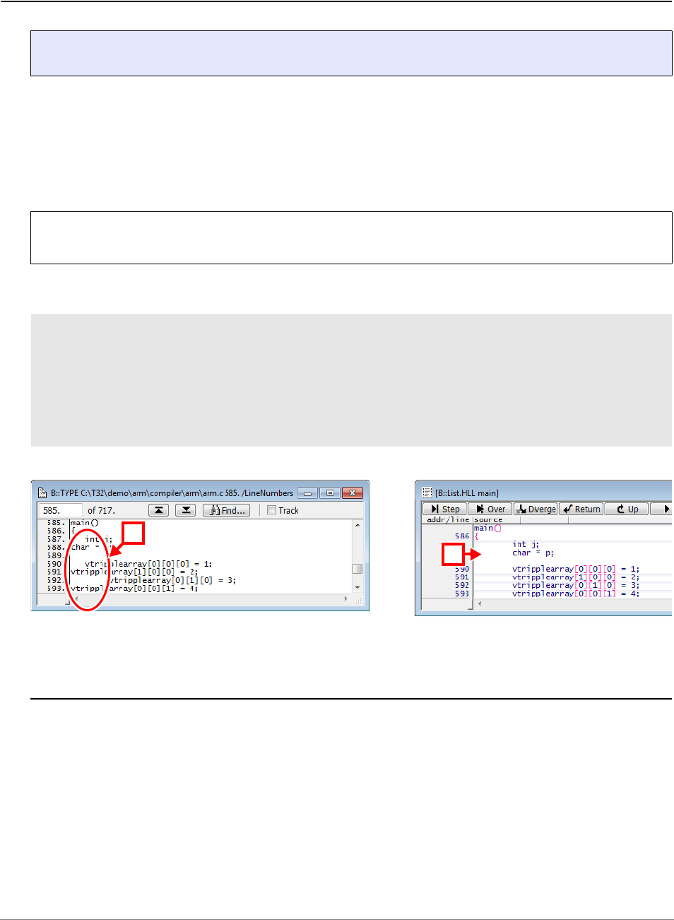
General Commands Reference Guide S | 235
©
1989-2024 Lauterbach
sYmbol.SourceBeautify Beautify HLL lines on loading
Example:
See also
■ sYmbol
Format: sYmbol.SourceBeautify [ON | OFF]
ON Beautifies the indentations of HLL lines displayed in the List windows.
The source file itself is not touched.
OFF Displays the HLL lines as formatted in the source file.
NOTE: The command takes only effect if it is set to ON or OFF before executing the
Data.LOAD.<file_format> command.
sYmbol.SourceBeautify ON
;load ELF file plus associated source file. For demo purposes, the *.c
;file contains some malformatted HLL lines.
Data.LOAD.ELF armle.axf /StripPATH /LowerPATH
List.HLL main ;refer to [B]
A Source file (*.c) with indentation issues. B Indentation issues fixed in TRACE32.
A
B

General Commands Reference Guide S | 236
©
1989-2024 Lauterbach
sYmbol.SourceCONVert Conversion for Japanese font
Converts the HLL source information from EUC (Extended UNIX Code) to JP for Windows.
See also
■ sYmbol
▲ ’Release Information’ in ’Legacy Release History’
Format: sYmbol.SourceCONVert <mode>
<mode>: OFF | EUC-JP

General Commands Reference Guide S | 237
©
1989-2024 Lauterbach
sYmbol.SourceLOAD Initiate the loading of an HLL source file
By default an HLL source file is only loaded by TRACE32 when the contents of the HLL source file is
required during debugging. The command sYmbol.SourceLOAD loads the HLL source file for the defined
module on user request. The HLL source line information from the absolute object file must be loaded before
using this command. If the command sYmbol.SourceLOAD is used without any parameter, all HLL source
files are loaded.
The command sYmbol.SourceLOAD allows also the specification of a new HLL source file instead of the
one listed in sYmbol.List.SOURCE. This can be useful, if the name or directory of the source file has been
changed after compilation.
Examples:
See also
■ sYmbol
Format: sYmbol.SourceLOAD [<module> [<file>]]
; load all source files
Data.LOAD.COFF arm.abs
sYmbol.SourceLOAD
; load the source file for the module \\thumble\arm
Data.LOAD.COFF arm.abs
sYmbol.List.SOURCE
sYmbol.SourceLOAD \\thumble\arm
; load the source file NewArm.C for the module \\thumble\arm
Data.LOAD.COFF arm.abs
sYmbol.SourceLoad \\thumble\arm G:\ARM\etc\Test\NewArm.C
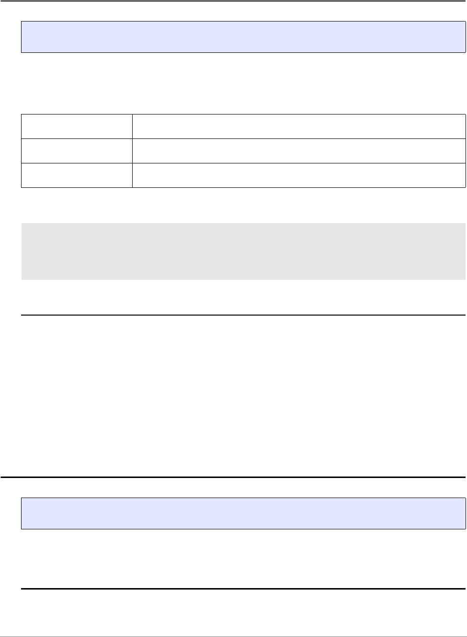
General Commands Reference Guide S | 238
©
1989-2024 Lauterbach
sYmbol.SourcePATH Source search path
Adds or removes directories to the path used for searching the source files accessed by TRACE32. The
current search order can be displayed by the command sYmbol.SourcePATH.List. The list can be saved
with the STOre command and the SPATH item.
Examples:
See also
■ sYmbol.SourcePATH.Delete ■ sYmbol.SourcePATH.DOWN
■ sYmbol.SourcePATH.List ■ sYmbol.SourcePATH.RESet
■ sYmbol.SourcePATH.Set ■ sYmbol.SourcePATH.SetBaseDir
■ sYmbol.SourcePATH.SetCache ■ sYmbol.SourcePATH.SetCachedDir
■ sYmbol.SourcePATH.SetCachedDirCache ■ sYmbol.SourcePATH.SetCachedDirIgnoreCache
■ sYmbol.SourcePATH.SetDir ■ sYmbol.SourcePATH.SetDynamicDir
■ sYmbol.SourcePATH.SetMasterDir ■ sYmbol.SourcePATH.SetRecurseDir
■ sYmbol.SourcePATH.SetRecurseDirCache ■ sYmbol.SourcePATH.SetRecurseDirIgnoreCase
■ sYmbol.SourcePATH.Translate ■ sYmbol.SourcePATH.TranslateSUBpath
■ sYmbol.SourcePATH.UP ■ sYmbol.SourcePATH.Verbose
■ sYmbol
sYmbol.SourcePATH.Delete Delete path from search list
Removes the specified directory from the search path.
See also
■ sYmbol.SourcePATH
Format: sYmbol.SourcePATH [+ | - | -- | <directory>] … (deprecated)
+ Use the '+' to add a directory to the path.
- Use the '-' sign to remove a path from the list.
-- Two minus signs ’--’ clear the whole list like sYmbol.RESet.
sYmbol.SourcePATH + c:\source\proj_1
sYmbol.SourcePATH + c:\mike\source\proj_1
…
sYmbol.SourcePATH - c:\source\proj_1
; add search directories
; remove search directory
Format: sYmbol.SourcePATH.Delete <directory>

General Commands Reference Guide S | 239
©
1989-2024 Lauterbach
sYmbol.SourcePATH.DOWN Make directory last in search order
Internal TRACE32 command. The specified directory becomes the last in the defined search order.
See also
■ sYmbol.SourcePATH
sYmbol.SourcePATH.List List source search paths
[Examples]
Lists defined search paths and their attributes.
Description of Toolbar Buttons in the sYmbol.SourcePATH.List Window
Format: sYmbol.SourcePATH.DOWN <directory>
Format: sYmbol.SourcePATH.List
sYmbol.List.SPATH (deprecated)
Delete All Reset all source path settings.
(command sYmbol.SourcePATH.RESet)
Reload Reload all loaded source files.
(command sYmbol.SourceRELOAD)
Verbose Enable/disable search details in the TRACE32 Message Area.
(command sYmbol.SourcePATH.Verbose ON | OFF)
Store… Save source path search setting to <file>.
(command STOre <file> SPATH)
Cache… Save source path search setting plus list of all cached files to <file>.
(Command STOre <file> SPATHCACHE)
Load… Load source path settings from <file>.
(command DO <file>)
AddDir Add directory as base directory and as direct directory to search path list.
(command sYmbol.SourcePATH <dir>)

General Commands Reference Guide S | 240
©
1989-2024 Lauterbach
Example for a base directory:
Example for direct directories:
; Define directory as base for relative paths
sYmbol.SourcePATH.SetBaseDir C:\T32_ARM\demo\sources
; directory is direct search path
sYmbol.SourcePATH.SetDir
C:\T32_ARM\demo\arm\hardware\imx53\quickstartboard\demo_drivers
; directory is direct search path, all source files found in the defined
; directory are cached by TRACE32
sYmbol.SourcePATH.SetCachedDir
C:\T32_ARM\demo\arm\hardware\imx53\quickstartboard\demo_net
; directory is direct search path, the directory and all its
; sub-directories are used as search path
sYmbol.SourcePATH.SetRecurseDir
C:\T32_ARM\demo\arm\hardware\imx53\quickstartboard\demo_ext
; directory is a direct search path, if the source file was found in
; this directory, this directory will become the first to be searched
; in
sYmbol.SourcePATH.SetDynamicDir
C:\T32_ARM\demo\arm\hardware\imx53\quickstartboard\demo_int

General Commands Reference Guide S | 241
©
1989-2024 Lauterbach
Example for translated paths:
See also
■ sYmbol.SourcePATH
▲ ’Release Information’ in ’Legacy Release History’
sYmbol.SourcePATH.RESet Reset search path configuration
Resets the search path configuration.
See also
■ sYmbol.SourcePATH
sYmbol.SourcePATH.Translate "Z:/Projects/own/trunk/V850/src/sieve"
"C:/T32_V850/demo/20131129trainings_demo/demo/v850/compiler/iar"
sYmbol.SourcePATH.Translate "C:/Programme/IAR Systems"
"C:/T32_V850/demo"
sYmbol.List.SourcePATH
Format: sYmbol.SourcePATH.RESet


General Commands Reference Guide S | 243
©
1989-2024 Lauterbach
sYmbol.SourcePATH.SetBaseDir Define directory as base for relative paths
Defines directory as base for relative paths.
See also
■ sYmbol.SourcePATH
▲ ’Release Information’ in ’Legacy Release History’
Format: sYmbol.SourcePATH.SetBaseDir <directory>
; load object file vmlinux and cut the following from the source paths:
; start of source path til end of "kernels-arm"
Data.LOAD.Elf ~~~~/vmlinux /StripPART "kernels-arm"
sYmbol.SourcePATH.SetBaseDir J:\AND\omap\sources
sYmbol.SourcePATH.List
sYmbol.List.SOURCE
source Source path provided by executable.
file Source path as modified by the Data.LOAD command
or
source path from which the file was loaded.

General Commands Reference Guide S | 244
©
1989-2024 Lauterbach
sYmbol.SourcePATH.SetCache Internal use only
Internal TRACE32 software command, not of interest for TRACE32 users.
See also
■ sYmbol.SourcePATH
sYmbol.SourcePATH.SetCachedDir Cache direct search path directory
All source files found in the defined directory are cached by TRACE32.
Example:
See also
■ sYmbol.SourcePATH
Format: sYmbol.SourcePATH.SetCache <file>
Format: sYmbol.SourcePATH.SetCachedDir {<directory>}
sYmbol.SourcePATH.SetCachedDir
C:\T32_ARM\demo\arm\hardware\imx53\quickstartboard\demo_net
STOre CacheCon SPATHCACHE ; generate a script for fast recaching

General Commands Reference Guide S | 245
©
1989-2024 Lauterbach
sYmbol.SourcePATH.SetCachedDirCache Internal use only
Internal TRACE32 software command, not of interest for TRACE32 users.
See also
■ sYmbol.SourcePATH
sYmbol.SourcePATH.SetCachedDirIgnoreCache Cache direct search path
All source files found in the defined directory are cached by TRACE32 ignoring lowercase/uppercase.
See also
■ sYmbol.SourcePATH
Format: sYmbol.SourcePATH.SetCachedDirCache <directory> …
Format: sYmbol.SourcePATH.SetCachedDirIgnoreCase {<directory>}
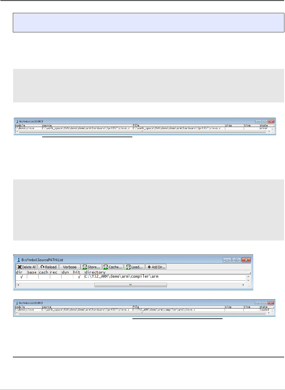
General Commands Reference Guide S | 246
©
1989-2024 Lauterbach
sYmbol.SourcePATH.SetDir Define directory as direct search path
The source files are directly searched in the defined directories.
Examples:
See also
■ sYmbol.SourcePATH
Format: sYmbol.SourcePATH.SetDir <directory>
Data.LOAD.Elf armle.axf ; load elf file
sYmbol.List.SOURCE ; display path information for
; source files
; define directory as direct search path
sYmbol.SourcePATH.SetDir C:\T32_ARM\demo\arm\compiler\arm
sYmbol.SourcePATH.List ; display search path defined by
; user
sYmbol.List.SOURCE ; display path information for
; source files
Source path provided by Elf file
error indicates that
the source file was
not found under the
provided path
Source path from which the file
was loaded

General Commands Reference Guide S | 247
©
1989-2024 Lauterbach
sYmbol.SourcePATH.SetDynamicDir Adjust search order at hit
The search order defined by this command is dynamically changed. The directory in which the last searched
source file was found becomes the first directory in which the debugger searches for the next source file.
Example:
See also
■ sYmbol.SourcePATH
Format: sYmbol.SourcePATH.SetDynamicDir {<directory>}
sYmbol.SourcePATH.SetDynamicDir
C:\T32_ARM\demo\arm\hardware\imx53\quickstartboard\demo_net
sYmbol.SourcePATH.SetDynamicDir
C:\T32_ARM\demo\arm\hardware\imx53\quickstartboard\demo_drivers
sYmbol.SourcePATH.SetDynamicDir
C:\T32_ARM\demo\arm\hardware\imx53\quickstartboard\demo_ext
sYmbol.SourcePATH.SetDynamicDir
C:\T32_ARM\demo\arm\hardware\imx53\quickstartboard\demo_int
sYmbol.SPATH.List

General Commands Reference Guide S | 248
©
1989-2024 Lauterbach
sYmbol.SourcePATH.SetMasterDir Store cached files only relative
If the command STOre <file> SPATHCACHE is used, all file names are only saved relative to the defined
directory.
Example:
See also
■ sYmbol.SourcePATH
Format: sYmbol.SourcePATH.SetMasterDir <directory>
Data.LOAD G:\AND\compiler\xc\bt800ip.iee
sYmbol.SourcePATH.SetCachedDir G:\AND\compiler\xc\System
sYmbol.SourcePATH.SetMasterDir G:\AND\compiler
STOre cache.cmm SPATHCACHE
// And Thu May 27 16:40:51 2004
B::
sYmbol.SourcePATH.SetCachedDirCache "xc\System"
sYmbol.SourcePATH.SetCache "xc\System"
(
"ad_cond.c"
"adsubs.c"
"bt_27.c"
"bt_27.h"
"bt_28.c"
"bt_flsh.c"
)
ENDDO

General Commands Reference Guide S | 249
©
1989-2024 Lauterbach
sYmbol.SourcePATH.SetRecurseDir Define recursive direct search path
Use the defined directory and all subdirectories as search path.
Example:
See also
■ sYmbol.SourcePATH
sYmbol.SourcePATH.SetRecurseDirCache Internal use only
Internal TRACE32 software command, not of interest for TRACE32 users.
See also
■ sYmbol.SourcePATH
Format: sYmbol.SourcePATH.SetRecurseDir {<directory>}
sYmbol.SourcePATH.SetRecurseDir
C:\T32_ARM\demo\arm\hardware\imx53\quickstartboard
Format: sYmbol.SourcePATH.SetRecurseDirCache <directory>…

General Commands Reference Guide S | 250
©
1989-2024 Lauterbach
sYmbol.SourcePATH.SetRecurseDirIgnoreCase Recursive search path
Use the defined directory and all subdirectories as search path. Lowercase/uppercase is ignored
See also
■ sYmbol.SourcePATH
sYmbol.SourcePATH.Translate Replace part of the source path
Replaces <original_path> in source path with <new_path>. Use case: The code was built on a remote
machine. Thus the base path must be replaced.
Format: sYmbol.SourcePATH.SetRecurseDirIgnoreCase {<directory>}
Format: sYmbol.SourcePATH.Translate <original_path> <new_path>

General Commands Reference Guide S | 251
©
1989-2024 Lauterbach
Example:
See also
■ sYmbol.SourcePATH
▲ ’Release Information’ in ’Legacy Release History’
Data.LOAD.Elf sieve.elf
sYmbol.List.SOURCE
sYmbol.SourcePATH.Translate "Z:/Projects/own/trunk/V850/src/sieve"
"C:/T32_V850/demo/20131129trainings_demo/demo/v850/compiler/iar"
sYmbol.SourcePATH.Translate "C:/Programme/IAR Systems"
"C:/T32_V850/demo"
sYmbol.List.SourcePATH

General Commands Reference Guide S | 252
©
1989-2024 Lauterbach
sYmbol.SourcePATH.TranslateSUBpath Replace sub-path
Replaces <original_sub_path> in source path with <new_sub_path>. Use case: Only a single folder is
different.
Example:
See also
■ sYmbol.SourcePATH
sYmbol.SourcePATH.UP Move path up in the search order
Internal TRACE32 command. The defined directory becomes the first in the search path order.
See also
■ sYmbol.SourcePATH
Format: sYmbol.SourcePATH.TranslateSUBpath <original_sub_path>
<new_sub_path>
sYmbol.SourcePATH.TranslateSUBpath "P5" "K8"
Format: sYmbol.SourcePATH.UP <directory>

General Commands Reference Guide S | 253
©
1989-2024 Lauterbach
sYmbol.SourcePATH.Verbose Display search details in message AREA
Default: OFF.
Example:
See also
■ sYmbol.SourcePATH
Format: sYmbol.SourcePATH.Verbose ON | OFF
OFF No details about the source file search are given.
ON Details about the source file search are displayed in the TRACE32
message AREA.view window, if a source file is loaded by TRACE32.
AREA.view ; open TRACE32 message AREA window
; to display source file search
; details
sYmbol.SourcePATH.Verbose ON
List ; display source listing
Verbose ON is indicated in the sYmbol.SourcePATH.List window

General Commands Reference Guide S | 254
©
1989-2024 Lauterbach
sYmbol.SourceRELOAD Reload source files
Invalidates all loaded source files and marks them for reload. This can be useful when the source search
path has been changed to reload the source modules that came from the old source path.
See also
■ sYmbol
sYmbol.STATE Display statistic
Displays the size of the symbol tables and the global settings. See also sYmbol.MEMory.
See also
■ sYmbol ■ sYmbol.Browse.sYmbol ■ sYmbol.INFO ■ sYmbol.List
❏ sYmbol.STATE()
▲ ’The Symbol Database’ in ’Training Source Level Debugging’
Format: sYmbol.SourceRELOAD
Format: sYmbol.STATE

General Commands Reference Guide S | 255
©
1989-2024 Lauterbach
sYmbol.STRIP Set max. symbol length
Cuts symbols to the specified length. This option is useful, when the compiler has a limited symbol length.
Example:
See also
■ sYmbol
sYmbol.TYPEINFO Display information about a specific data type
Displays information about a specific data type. Alternatively, right-click a data type in a sYmbol.List.Type
window, and then select View Details, or double-click a data type in that window.
See also
■ sYmbol
Format: sYmbol.STRIP [<length>]
sYmbol.STRIP 8.
Data.List Main_Function
; will display 'Main_Fun'
Format: sYmbol.TYPEINFO <data_type>
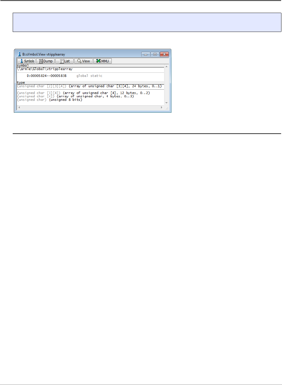

General Commands Reference Guide S | 257
©
1989-2024 Lauterbach
SYnch
SYnch Synchronization mechanisms between different TRACE32 systems
See also
■ SYnch.Connect ■ SYnch.MasterBreak ■ SYnch.MasterGo ■ SYnch.MasterStep
■ SYnch.MasterSystemMode ■ SYnch.OFF ■ SYnch.ON ■ SYnch.RESet
■ SYnch.SlaveBreak ■ SYnch.SlaveGo ■ SYnch.SlaveStep ■ SYnch.SlaveSystemMode
■ SYnch.state ■ SYnch.XTrack ■ TargetSystem ■ InterCom
Overview SYnch
For AMP multicore debugging and multiprocessor debugging, two or more TRACE32 PowerView instances
need to be started. The command group SYnch allows to establish a connection between different
TRACE32 instances for the following purposes:
• To establish a start/stop synchronization between the cores/processors controlled by different
TRACE32 instances.
• To allow concurrent assembler single steps between the cores/processors controlled by different
TRACE32 instances.
• To allow synchronous system mode changes between the cores/processors controlled by
different TRACE32 instances.
• To get a time synchronization between trace information in different TRACE32 instances. This
requires that the trace information uses a common time base, e.g. global TRACE32 timestamp or
global chip timestamps.
For configuration of the synchronization mechanisms, use the TRACE32 command line, a PRACTICE script
(*.cmm), or the SYnch.state window. See also prerequisite [A] below.
A Prerequisite: You have set up an InterCom system using the InterCom commands, which allows to
exchange data between different TRACE32 systems.
A

General Commands Reference Guide S | 258
©
1989-2024 Lauterbach
SYnch.Connect Connect to other TRACE32 PowerView instances
Format 1: Establishes connections via the InterCom system to other TRACE32 PowerView instances that
are connected to same PowerDebug hardware module or the same MCI Server (PBI=MCISERVER in the
config.t32 file).
Format 2: Establishes connections to other TRACE32 instances by using the InterCom system.
Format 1 and Format 2: SYnch.ON is automatically set when the command SYnch.Connect establish the
connections.
Example 1 for Format 2: This script line connects two instances based on their host names and port
numbers.
Example 2 for Format 1 and Format 2: This script line disconnects the TRACE32 instances.
Format 1: SYnch.Connect [<instances> …]
<instances>: <intercom_name> | ALL | OTHERS | <name_pattern> | [<host>:]<port>
Format 2: SYnch.Connect [<host>:]<port> …
(without parameters)
Format 1, Format 2
If the command is used without parameters, it disconnects the TRACE32
PowerView instances.
<intercom_name>
Format 1
InterCom name of a TRACE32 instance. Names can be assigned to
TRACE32 instances with the InterCom.NAME command.
The InterCom.execute command supports the wildcards * and ? in
InterCom names.
<name_pattern>
Format 1
The SYnch.Connect command supports the wildcards * and ? in
InterCom names. For example: cluster1.*
ALL
Format 1
All known TRACE32 instances.
OTHERS
Format 1
ALL except SELF.
<host>:<port>
Format 1, Format 2
Name of the host and the port number.
SYnch.Connect localhost:20001 localhost:20002
SYnch.Connect

General Commands Reference Guide S | 259
©
1989-2024 Lauterbach
Example 3 for Format 1: All instances are connected except the one where this command is executed.
Example 4 for Format 1: The command SYnch.Connect OTHERS is executed on all TRACE32 instances.
See also
■ SYnch ■ SYnch.state ■ InterCom.ENable ■ InterCom.NAME
▲ ’Release Information’ in ’Legacy Release History’
SYnch.Connect OTHERS
InterCom.execute ALL SYnch.Connect OTHERS

General Commands Reference Guide S | 260
©
1989-2024 Lauterbach
SYnch.MasterBreak Invite other TRACE32 to stop synchronously
Default: OFF
SYnch.MasterBreak and SYnch.SlaveBreak can be freely programmed for the connected TRACE32
instances. But the break switch/cross trigger unit in the multicore chip might not provide resources to
program all links. TRACE32 adjust the programming of the links to the available resources in this case.
See also
■ SYnch ■ SYnch.state
Format: SYnch.MasterBreak [ON | OFF]
ON Invite other TRACE32 instances to stop synchronously.
Cores in a multicore chip can be stopped instruction-accurate if the chip
provides a break switch/cross trigger unit.
Otherwise software-controlled stop synchronization is used. Software-
controlled synchronization stop the cores/processors one by one with a
minimum delay of 1.ms.
OFF No invitation for a synchronous stop is broadcast to other TRACE32
instances.

General Commands Reference Guide S | 261
©
1989-2024 Lauterbach
SYnch.MasterGo Invite other TRACE32 to start synchronously
See also
■ SYnch ■ SYnch.state
SYnch.MasterStep Invite other TRACE32 to Asm step synchronously
See also
■ SYnch ■ SYnch.state
Format: SYnch.MasterGo [ON | OFF]
OFF
(default)
No invitation for a synchronous start is broadcast to other TRACE32
instances.
ON Invite other TRACE32 instances to start synchronously.
Cores in a multicore chip can start synchronously if this is supported by
the chip.
Otherwise software-controlled start synchronization is used. software-
controlled synchronization starts the cores/processors one by one with a
minimum delay of 1.ms.
Format: SYnch.MasterStep [ON | OFF]
OFF
(default)
No invitation for concurrent assembler single stepping is broadcast to
other TRACE32 instances.
ON Invite other TRACE32 instances to perform concurrent assembler single
stepping. HLL single stepping is regarded as a synchronous start.

General Commands Reference Guide S | 262
©
1989-2024 Lauterbach
SYnch.MasterSystemMode Invite other TRACE32 to follow mode change
See also
■ SYnch ■ SYnch.state
SYnch.OFF Disable connection mechanism
Disables the software component that allows a TRACE32 instance to connect to other instances.
See also
■ SYnch ■ SYnch.state
SYnch.ON Enable connection mechanism
Enables the software component that allows a TRACE32 instance to connect to other instances.
See also
■ SYnch ■ SYnch.state
Format: SYnch.MasterSystemMode [ON | OFF]
OFF
(default)
No invitation for synchronous mode changing is broadcast to other
TRACE32 instances.
ON Invite other TRACE32 instances to perform system mode changes
synchronously. System mode changes are typically performed by one of
the following commands: SYStem.Up, SYStem.Mode <mode>
commands and SYStem.RESetTarget.
Format: SYnch.OFF
Format: SYnch.ON

General Commands Reference Guide S | 263
©
1989-2024 Lauterbach
SYnch.RESet Reset SYnch mechanism
Resets the SYnch mechanism to its default settings.
See also
■ SYnch ■ SYnch.state
SYnch.SlaveBreak Synchronize with stop in connected TRACE32
See also
■ SYnch ■ SYnch.state
Format: SYnch.RESet
Format: SYnch.SlaveBreak [ON | OFF]
OFF Don’t synchronize with the stop of the program execution in a connected
TRACE32 instance.
ON Synchronize with the stop of the program execution in a connected
TRACE32 instance.
Cores in a multicore chip can be stopped instruction-accurate if the chip
provides a break switch/cross trigger unit.
Otherwise software-controlled stop synchronization is used. Software-
controlled synchronization stop the cores/processors one by one with a
minimum delay of 1.ms.

General Commands Reference Guide S | 264
©
1989-2024 Lauterbach
SYnch.SlaveGo Synchronize with start in connected TRACE32
See also
■ SYnch ■ SYnch.state
SYnch.SlaveStep Synchronize with asm step in connected TRACE32
See also
■ SYnch ■ SYnch.state
Format: SYnch.SlaveGo [ON | OFF]
OFF Don’t synchronize with the start of the program execution in a connected
TRACE32 instance.
ON Synchronize with the start of the program execution in a connected
TRACE32 instance.
Cores in a multicore chip can start synchronously if this is supported by
the chip.
Otherwise software-controlled start synchronization is used. software-
controlled synchronization starts the cores/processors one by one with a
minimum delay of 1.ms.
Format: SYnch.SlaveStep [ON | OFF]
OFF Don’t synchronize with assembler single steps in a connected TRACE32
instance.
ON Synchronize with assembler single steps in a connected TRACE32
instance.

General Commands Reference Guide S | 265
©
1989-2024 Lauterbach
SYnch.SlaveSystemMode Synch. with mode changes in other TRACE32
See also
■ SYnch ■ SYnch.state
SYnch.state Display current SYnch settings
Displays the current setup of the SYnch mechanism.
See also
■ SYnch ■ SYnch.Connect ■ SYnch.MasterBreak ■ SYnch.MasterGo
■ SYnch.MasterStep ■ SYnch.MasterSystemMode ■ SYnch.OFF ■ SYnch.ON
■ SYnch.RESet ■ SYnch.SlaveBreak ■ SYnch.SlaveGo ■ SYnch.SlaveStep
■ SYnch.SlaveSystemMode ■ SYnch.XTrack
Format: SYnch.SlaveSystemMode [ON | OFF]
OFF Don’t synchronize with system mode changes in connected TRACE32
instances.
ON Synchronize with system mode changes in connected TRACE32
instances.
Format: SYnch.state
A For descriptions of the commands in the SYnch.state window, please refer to the SYnch.*
commands in this chapter. Example: For information about ON, see SYnch.ON.
A

General Commands Reference Guide S | 266
©
1989-2024 Lauterbach
SYnch.XTrack Establish time synchronization to another TRACE32 instance
Establishes a time synchronization between trace information in different TRACE32 instances via the
InterCom system. This requires that the trace information uses a common time base e.g. global TRACE32
time stamps or global chip timestamps.
Format 1: Establishes a time synchronization to other TRACE32 PowerView instances that are connected
to same PowerDebug hardware module or the same MCI Server (PBI=MCISERVER in the config.t32 file).
Format 2: Establishes a time synchronization to other TRACE32 PowerView instances in general.
Example 1 for Format 1:
Format 1: SYnch.XTrack [<instances> …]
<trace>.XTrack <intercom_name> (deprecated)
<instances>: <intercom_name> | ALL | OTHERS | <name_pattern>
Format 2: SYnch.XTrack [<host>:]<port> …
(without parameters)
Format 1, Format 2
If the command is used without parameters, it disconnects the TRACE32
PowerView instances.
<intercom_name>
Format 1
InterCom name of a TRACE32 instance. Names can be assigned to
TRACE32 instances with the InterCom.NAME command.
The InterCom.execute command supports the wildcards * and ? in
InterCom names.
<name_pattern>
Format 1
The SYnch.Connect command supports of the wildcards * and ? in
InterCom names. For example: cluster1.*
ALL
Format 1
All known TRACE32 instances.
OTHERS
Format 1
ALL except SELF.
<host>:<port>
Format 2
Name of the host and the port number.
; all instances are connected to each other
InterCom.execute ALL SYnch.XTrack OTHERS
; trace commands in one TRACE32 instance
Trace.List /Track
Trace.Chart.sYmbol /ZoomTrack

General Commands Reference Guide S | 267
©
1989-2024 Lauterbach
Example 2 for Format 2:
See also
■ SYnch ■ SYnch.state
; connect the instance where SYnch.XTrack is executed with the other two
; instances ‘localhost:20001’ and ‘localhost:20002’
SYnch.XTrack localhost:20001 localhost:20002
; trace commands in one TRACE32 instance
Trace.List /Track
Trace.Chart.sYmbol /ZoomTrack

General Commands Reference Guide S | 268
©
1989-2024 Lauterbach
SYStem
SYStem System configuration
The SYStem commands are used for setting the operating modes of the system. In addition, they are used
to define all those parameters which remain valid after stopping the emulation. The subcommands of the
SYStem command group are highly target-dependent; for details, check the Processor Architecture
Manual for your target system.
In general, the configuration commands (e.g. SYStem.Option) should be used before the emulation system
is activated with the SYStem.Mode or SYStem.Up command. Changing configuration options while the
system is up may cause unpredictable behavior.
SYStem.BdmClock Select BDM clock
Either the divided CPU frequency is used as the BDM clock or a fixed clock rate. The fixed clock rate must
be used if the operation frequency is very slow or if the clock line is not available. The default is a fixed rate of
1MHz.
See also
■ SYStem.state
Format: SYStem.BdmClock <rate> (deprecated)
Use SYStem.JtagClock instead.
<rate>: 2 | 4 | 8 | 16 | <fixed>
<fixed>: 1000. … 5000000.

General Commands Reference Guide S | 269
©
1989-2024 Lauterbach
SYStem.BREAKTIMEOUT Define the used timeout for break
The Break.direct command performs a break request and waits for 3.s for the target to stop, otherwise an
“emulation running” error is reported. The command SYStem.BREAKTIMEOUT can be use to specify a
different timeout.
See also
■ SYStem.state
Format: SYStem.BREAKTIMEOUT <time>

General Commands Reference Guide S | 270
©
1989-2024 Lauterbach
SYStem.CADICommand Send a command to target
Sends the <command> as string to the target. <command> is accepted without ' " '. The command is send
via CADI function 'CADIXfaceBypass()'. If an answer is provided, it will be displayed in AREA.view
beginning with "Answer: ".
See also
■ SYStem.state
Format: SYStem.CADICommand <command>

General Commands Reference Guide S | 271
©
1989-2024 Lauterbach
SYStem.CADIconfig CADI-specific setups
Virtual targets only: CADI
The SYStem.CADIconfig command group is used to define CADI-specific setups for debugging and
tracing.
See also
■ SYStem.CADIconfig.ExecSwOnly ■ SYStem.CADIconfig.RemoteServer
■ SYStem.CADIconfig.SpecRegDefine ■ SYStem.CADIconfig.SpecRegsOnly
■ SYStem.CADIconfig.Traceconfig ■ SYStem.CADIconfig.TraceCore
■ SYStem.IRISconfig ■ SYStem.state
SYStem.CADIconfig.ExecSwOnly Filter on executing software capability
Default = ON.
See also
■ SYStem.CADIconfig
SYStem.CADIconfig.RemoteServer Define connection to CADI server
Virtual targets only: CADI
Informs TRACE32 how to connect to the CADI server for debugging purposes. If this command is omitted
from your start-up script, then TRACE32 assumes that the virtual target (including the CADI server) and
TRACE32 are running on the same machine.
Without arguments: Resets the connection to a configuration where TRACE32 and the virtual target are
assumed to be running on the same machine (localhost).
Format: SYStem.CADIconfig.ExecSwOnly ON | OFF
ON TRACE32 connects just to CADI instances which can execute
software (CADI internal flag .executesSoftware is set).
OFF TRACE32 connects to any core or instance via CADI, regardless its
capability of executing software.
Format: SYStem.CADIconfig.RemoteServer [<ip> <port>]

General Commands Reference Guide S | 272
©
1989-2024 Lauterbach
With arguments: Defines a connection to the CADI server on a remote computer. Ensure that your CADI
server allows remote connections.
Examples:
See also
■ SYStem.CADIconfig ❏ SYStem.CADIconfig.RemoteServer()
<ip> IP address or host name of the remote computer where the virtual target
is running.
<port> Parameter Type: Decimal value. TCP/IP port of the CADI server.
SYStem.CADIconfig.RemoteServer
SYStem.CADIconfig.RemoteServer 192.168.178.2 7002.
SYStem.CADIconfig.RemoteServer RmtPC 7000.
Host 1 Host 2
TRACE32
t32caditrace.dll
Virtual target
(incl. CADI server)
t32cadi.dll
Debug Connection
via CADI
Optional Trace Connection via TCP/IP
Figure 1 of 2: The red line illustrates the connection that is defined as a remote connection using the
SYStem.CADIconfig.RemoteServer command.
localhost
TRACE32
t32caditrace.dll
Virtual target
(incl. CADI server)
t32cadi.dll
Debug Connection
via CADI
Optional Trace Connection via TCP/IP
Figure 2 of 2: The red line illustrates the localhost connection that is defined using the
SYStem.CADIconfig.RemoteServer command.

General Commands Reference Guide S | 273
©
1989-2024 Lauterbach
SYStem.CADIconfig.SpecRegDefine Define special register set
With SYStem.CADIconfig.SpecRegDefine a generic read and write access to registers which are not part
of the regular CPU architecture register sets and its peripherals can be defined. The special defined register
is searched from the complete CADI provided register list. SYStem.CADIconfig.SpecRegDefine without
any parameter deletes the complete special register definition (=default). A maximum of six registers can be
defined.
See also
■ SYStem.CADIconfig
SYStem.CADIconfig.SpecRegsOnly Use only special defined register set
Default = OFF.
See also
■ SYStem.CADIconfig
Format: SYStem.CADIconfig.SpecRegDefine {<offset> <Reg name>}
<offset> Address offset in hex format to access the register named with <Reg
name>. The offset is add to the CADI base address for special
registers defines (= DBG:0C0000000). Maximum offset value is
0x0FFFFF, higher values are masked with 0x0FFFFF.
<Reg name> Name of the special defined register as case sensitive string.
Maximum string length is 27 characters.
Format: SYStem.CADIconfig.SpecRegsOnly ON | OFF
ON TRACE32 searches only for special defined registers (see
SYStem.CADIconfig.SpecRegDefine)
OFF TRACE32 searches for regular register sets defined by SYStem.CPU selection
and for special defined registers.

General Commands Reference Guide S | 274
©
1989-2024 Lauterbach
SYStem.CADIconfig.Traceconfig Define network settings to CADI trace
Virtual targets only: CADI
Without arguments: Defines a connection to the trace plug-in based on the default values. The file name of
the trace plug-in is t32caditrace.dll / t32caditrace.so.
With arguments: Defines a user-defined connection to the trace plug-in.
The red line illustrates the connection that is defined using the SYStem.CADIconfig.Traceconfig
command.
See also
■ SYStem.CADIconfig ❏ SYStem.CADIconfig.Traceconfig()
▲ ’Introduction’ in ’Virtual Targets User’s Guide’
SYStem.CADIconfig.TraceCore Define core for CADI trace
Defines the core for which the CADI trace feature will be active in the case of SMP core setup. CADI trace
allows just one core to be traced.
See also
■ SYStem.CADIconfig
Format: SYStem.CADIconfig.Traceconfig [<ip> <port>]
<ip>
(default: 127.0.0.1)
IP address of the host machine where the virtual target is running.
IPv4 only. Host names are not allowed.
<port>
(default: 21000.)
Parameter Type: Decimal value. TCP/IP port of the trace plug-in.
Format: SYStem.CADIconfig.TraceCore <Corenumber>
t32caditrace.dll
Trace Connection
via TCP/IP
Virtual target
(including CADI server)
Debug Connection
via CADI
t32cadi.dllTRACE32

General Commands Reference Guide S | 275
©
1989-2024 Lauterbach
SYStem.CONFIG Configure debugger according to target topology
The commands of the SYStem.CONFIG command group describe the target configuration to the debugger.
See also
■ SYStem.CONFIG.STM ■ SYStem.state
▲ ’Release Information’ in ’Legacy Release History’
Format: SYStem.CONFIG <parameter>
SYStem.MultiCore (deprecated)
<parameter> The supported parameters highly depend on the target processor
architecture. Please refer to the description of the SYStem.CONFIG
command in your Processor Architecture Manual for more information.

General Commands Reference Guide S | 276
©
1989-2024 Lauterbach
SYStem.CONFIG.CORE Assign core to TRACE32 instance
[Examples]
If the target provides a joint debug interface for several cores/chips it is necessary to inform the TRACE32
instance which core/chip it controls for debugging. This means, SYStem.CONFIG.CORE tells TRACE32 to
which specified <core> and <chip> it has to connect when the SYStem.Up command is executed.
Most architectures have 1 <chip> with several <cores>. Architectures with 2 or more <chips> are relatively
rare.
Next:
• Description of Format 1 for Physical Targets including example.
• Description of Format 2 for Virtual Targets including examples.
Format 1 for Physical Targets
Format 1: SYStem.CONFIG.CORE <core | thread> <chip>
SYStem.MultiCore.CORE (deprecated)
Format 2:
Virtual targets only
SYStem.CONFIG.CORE <string> | <value>
<core> Specify the core within the chip that is controlled by the TRACE32
instance.
The command SYStem.CONFIG.CORE <core> is mainly used, if the
cores within a chip are not daisy-chained, or daisy-chained and
interrelated. The <core> index is also used by the command
CORE.NUMber as start value to set up an SMP system.
See also Example for <core> and <chip>.
<chip> Specify which cores belong to the same chip if several chips are daisy-
chained.
This allows the debugger to coordinate chip-wide resources e.g. chip
reset, cross trigger matrix, shared trace port etc. Key for this coordination
is that TRACE32 is aware of the chip.

General Commands Reference Guide S | 277
©
1989-2024 Lauterbach
Format 2 for Virtual Targets
MCD Interface - Syntax Rules for <string> - Format 2 of SYStem.CONFIG.CORE
To specify unique strings identifying cores, observe the following rules for <string> and take the screenshot
below into account for a better understanding of these rules:
•The <string> is case-sensitive.
•The <string> starts at the first column to the left of the core # column:
• In the <string>, each column of the SYStem.CONFIG.ListCORE window is represented by a |
character (vertical line). To ignore one or more columns, type one | per column to be ignored:
<string> Unique string identifying the core to which TRACE32 connects in a virtual
target.
The syntax rules for <string> differ for the MCD and the CADI interface:
•See MCD interface
•See CADI interface
See also example for <string> in an SMP system. This simple example
applies to the MCD and the CADI interface.
<value> Core number identifying the core to which TRACE32 connects in a virtual
target.
The same <value> is displayed in the core # column of the
SYStem.CONFIG.ListCORE window.
The example for <value> applies to the MCD and the CADI interface.
; col.1 col.2 col.3 col.4
SYStem.CONFIG.CORE "<core>|<device>|<system_instance>|<system>"
SYStem.CONFIG.CORE "||4:1" ;ignore columns 1 and 2, and connect
;to the core having this unique
;sub-string ‘4:1’ in column 3
1234

General Commands Reference Guide S | 278
©
1989-2024 Lauterbach
• You can specify (a) an entire row or (b) the contents of one or more cells (cell = intersection of
column and row) or (c) just a sub-string of a cell:
• Wildcards like * and ? are not supported.
• For SMP systems: To connect to two or more cores, separate their unique strings or sub-strings
with a comma:
;(a) entire row - the ellipsis ... is used for space economy
SYStem.CONFIG.CORE "HARDWARE.ARM0.cpu3|HARDWARE.ARM0|...|..."
;(b) content of one cell
SYStem.CONFIG.CORE "HARDWARE.ARM0.cpu3"
;(c) sub-string from cell
SYStem.CONFIG.CORE "cpu3"
;connect to cpu1 and cpu2
SYStem.CONFIG.CORE "cpu1,cpu2"
;let’s take the sub-strings ‘4:0’ and 4:1’ from column 3 into
;account
SYStem.CONFIG.CORE "cpu0||4:0,cpu3||4:1"

General Commands Reference Guide S | 279
©
1989-2024 Lauterbach
CADI Interface - Syntax Rules for <string> - Format 2 of SYStem.CONFIG.CORE
To specify unique strings identifying cores, observe the following rules for <string> and take the screenshot
below into account for a better understanding of these rules:
•The <string> is case-sensitive.
•The <string> always contains the instance or a part of it, and may contain the Simulation ID:
• Information from columns other than Simulation ID and instance cannot be used to define a
connection to a core.
• Wildcards like * and ? are not supported.
• For SMP systems: To connect to two or more cores, separate their unique strings or sub-strings
with a comma:
;connect to a core by just specifying the instance
SYStem.CONFIG.CORE "cluster.cpu0"
;connect to a core by specifying the Simulation ID and the instance
SYStem.CONFIG.CORE "7000|cluster.cpu0"
;connect to cpu0 and cpu3, see instance column
SYStem.CONFIG.CORE "cpu0,cpu3"
;let’s take the Simulation ID into account
SYStem.CONFIG.CORE "7000|cpu0,7000|cpu3"
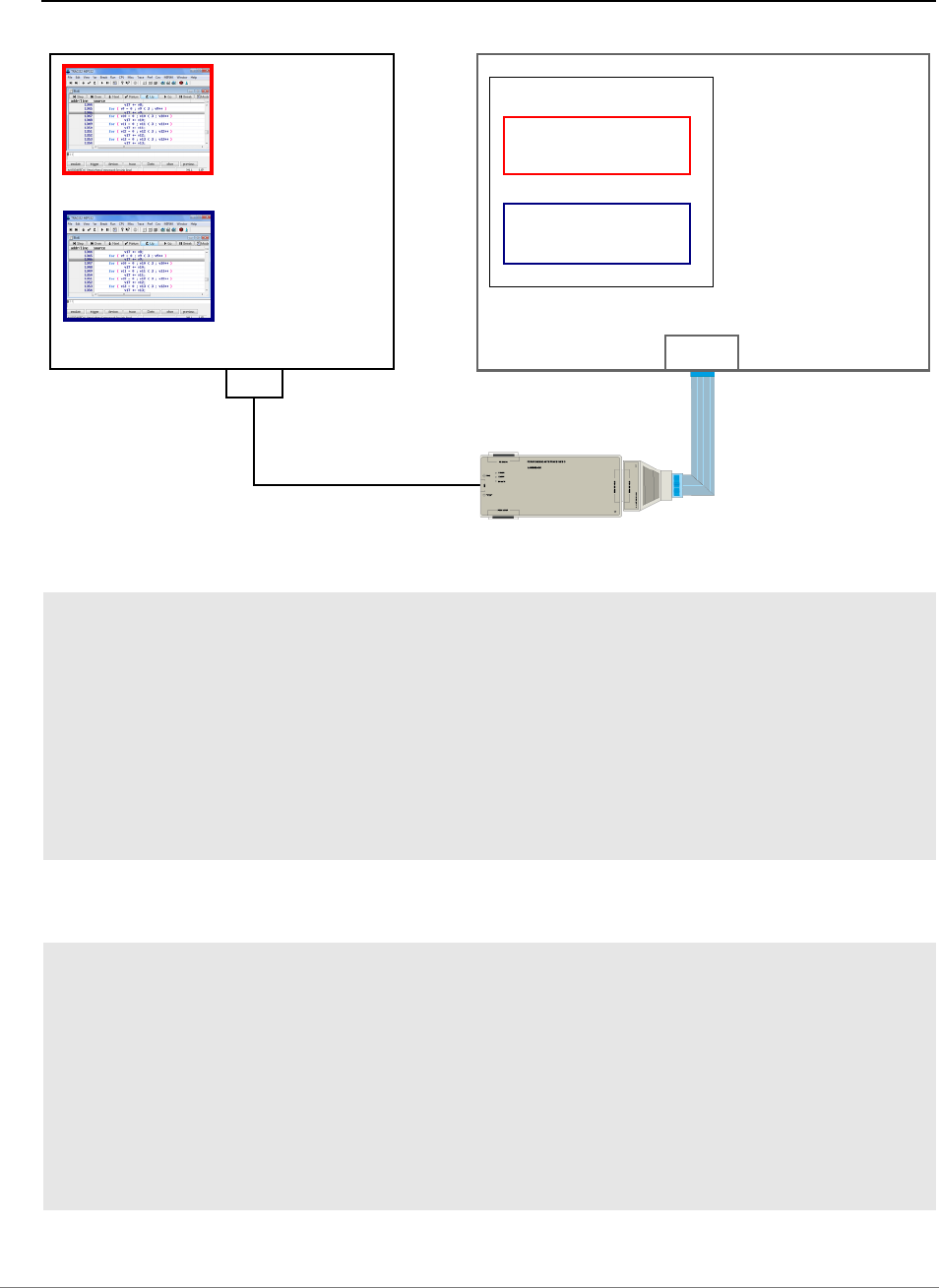
General Commands Reference Guide S | 280
©
1989-2024 Lauterbach
Example for <core> and <chip> - Format 1 of SYStem.CONFIG.CORE
Example for the MPC5517 (one chip with 2 cores)
Start-up commands for the e200z1 core:
Start-up commands for the e200z0 core:
SYStem.RESet ; reset all SYStem settings
SYStem.CPU MPC5517 ; select MPC5517 as target
; processor
; <core> <chip>
SYStem.CONFIG.CORE 1. 1.
; assign the TRACE32 instance to
; core 1 (e200z1), chip 1
SYStem.Up ; establish the communication
; between the debugger and the
; e200z1 core
SYStem.RESet ; reset all SYStem settings
SYStem.CPU MPC5517 ; select MPC5517 as target
; processor
; <core> <chip>
SYStem.CONFIG.CORE 2. 1.
; assign the TRACE32 instance to
; core 2 (e200z0), chip 1
SYStem.Mode.Attach ; establish the communication
; between the debugger and the
; e200z1 core
TRACE32 Instance for e200z1 Core
TRACE32 Instance for e200z0 Core
HOST
USB Interface
Joint JTAG Interface
e200z1 Core
TARGET
MPC5517
e200z0 Core
CORE 1.
CORE 2.

General Commands Reference Guide S | 281
©
1989-2024 Lauterbach
Example for <string> - Format 2 of SYStem.CONFIG.CORE
This simple example applies to the MCD and the CADI interface in an SMP system. Steps that are
specific to SMP systems are flagged with ‘(SMP system)’ in the comments:
Example for <value> - Format 2 of SYStem.CONFIG.CORE
This example applies to the MCD and CADI Interface.
See also
■ SYStem.CONFIG.ListCORE ■ CORE.ASSIGN
SYStem.DOWN
SYStem.CONFIG.ListCORE ;list the cores of a virtual target in
;the SYStem.CONFIG.ListCORE window.
SYStem.CPU CortexA9MPCore ;select a multicore CPU (SMP system)
SYStem.CONFIG.CoreNumber 2 ;set up the number of cores you want
CORE.NUMber 2 ;TRACE32 to connect to (SMP system)
SYStem.CONFIG.CORE "cpu1,cpu2" ;connect to cpu1 and cpu2 (SMP system)
;NOTE: In the ‘Cores’ pull-down list,
;cpu1 becomes core 0 and
;cpu2 becomes core 1.
;The ‘Cores’ pull-down list is accessible
;via the TRACE32 state line.
SYStem.Up
SYStem.DOWN
SYStem.CONFIG.ListCORE ;list the cores of a virtual target in the
;SYStem.CONFIG.ListCORE window
;the core <values> are displayed in the
;'core #' column. TRACE32 connects to the core
;having the specified <value>
; <value>
SYStem.CONFIG.CORE 2.
SYStem.Up

General Commands Reference Guide S | 282
©
1989-2024 Lauterbach
SYStem.CONFIG.CoreNumber Set up number of hardware threads
Sets up the number of hardware threads that are available inside the chip. The access to the particular
hardware threads can be configured by architecture specific SYStem.CONFIG commands described in
your Processor Architecture Manual. The defined hardware threads can be used by the CORE
commands to set up an SMP system.
An error message is displayed below the command line if the command is used for single-core CPUs.
See also
❏ CONFIGNUMBER()
Format: SYStem.CONFIG.CoreNumber <number>

General Commands Reference Guide S | 283
©
1989-2024 Lauterbach
SYStem.CONFIG.DEBUGPORT Specify debugport
Debugging via a functional interface of the host computer (<dp_fi> parameters)
Debugging via a functional interface is only supported for certain architectures. Please refer to the
Lauterbach home page for details.
Please refer to “TRACE32 Debug Back-Ends” (backend_overview.pdf) for setup details.
Format: SYStem.CONFIG.DEBUGPORT <dp_fi> |<dp_emu> |<dp_hw>
<dp_fi>: Unknown
CSWP0
IntelUSB0
SNEAKPEEK0
XCP0
<dp_emu>: GTL0 | GTL1 | GTL2 | GTL3 | GTL4
InfineonDAS0
VerilogTransactor0
Unknown
<dp_hw> : DebugCable0
DebugCableA | DebugCableB
Interface Protocol
Unknown (default)
CSWP0 USB Arm CoreSight Wire Protocol
IntelUSB0 USB Intel DCI Protocol
SNEAKPEEK0 TCP/IP MIPI SneakPeek Protocol
XCP0 TCP/IP ASAM MCD-1 XCP Protocol

General Commands Reference Guide S | 284
©
1989-2024 Lauterbach
Debugging a RTL simulation or emulation (<dp_emu> parameters)
Debugging a RTL simulation or emulation is only supported for certain architectures. Please refer to the
Lauterbach homepage for details.
Please refer to “TRACE32 Debug Back-Ends” (backend_overview.pdf) for setup details.
Debugging via TRACE32 hardware (<dp_hw> parameter)
The command SYStem.CONFIG.DEBUGPORT <dp_hw> is only needed for a PowerDebug plus
CombiProbe configuration and that only if two Whisker cables are connected to the CombiProbe.
If two whiskers are connected to the CombiProbe, the following must essentially be observed:
You need to ensure that each whisker has a master PowerView instance. In single debug port scenarios, the
first PowerView instance started is automatically a master. In a dual debug port scenario, you must specify
the master PowerView instance yourself for the second whisker using the SYStem.CONFIG.Slave OFF
command. Details about the command can be found in your Processor Architecture Manual manual.
Please be aware that SYStem.RESet also resets the SYStem.CONFIG.DEBUGPORT and
SYStem.CONFIG.Slave settings. So if you want to use one of the Lauterbach demo scripts for the second
whisker, you probably have to adapt the script.
Communication via
Unknown (default)
GTL<n> Generic Transactor Library designed by Lauterbach, e.g. GTL0
InfineonDAS0 Infineon DAS Server
VerilogTransactor0 Verilog Transactors
for testing the low-level communication, not suitable for debugging

General Commands Reference Guide S | 285
©
1989-2024 Lauterbach
There are two dual-whisker setups:
1. CombiProbe with two connected MIP20T-HS whiskers for debugging via two connectors.
If SoC 1 is debugged via the first debug connector (cable A whisker),
must be set in each TRACE32 instance that controls cores of this SoC.
Analogously, if SoC 2 is debugged via the second debug connector (cable B whisker)
must be set in each TRACE32 instance that controls cores of this SoC.
Debugging via two debug connectors is also possible using two MIPI34 whiskers and a
CombiProbe 2. However if you are still using a CombiProbe, it is recommended to contact
Lauterbach support in advance.
2. CombiProbe with two connected AUTO26 whiskers for dsPIC33 dual core debugging.
A dual core dsPIC33 needs a CombiProbe with two AUTO26 whiskers for debugging, because each
core has its own debug connector. In the required AMP setup, the following setting must be made in
the TRACE32 instance controlling the first core (cable A whisker):
SYStem.CONFIG.DEBUGPORT DebugCableA
SYStem.CONFIG.DEBUGPORT DebugCableB
SYStem.CONFIG.DEBUGPORT DebugCableA
POWER DEBUG E40
POWER DEBUG E40
PC or
Workstation
USB
Cable
Target with Two SoCs
CombiProbe
A
MIPI 20T / MIPI 10
Connector 1
for SoC 1
B
MIPI 20T / MIPI 10
Connector 2
for SoC 2

General Commands Reference Guide S | 286
©
1989-2024 Lauterbach
Analogously, the following must be set in the TRACE32 instance controlling the second core (cable B
whisker):
There exist ready-to-run dual-whisker scripts from Lauterbach for this core architecture.
SYStem.CONFIG.DEBUGTIMESCALE Extend debug driver timeouts
Extends any timing behavior of the debug driver by the passed <multiplier>.
The timing behavior should be adapted in case the debugger is connected to an emulator that runs with a
much smaller clock compared to a silicon target. The original timeout settings may cause timeouts or bus
errors in this scenario.
SYStem.CONFIG.DEBUGPORT DebugCableB
Format: SYStem.CONFIG.DEBUGTIMESCALE <multiplier>
<multiplier> The <multiplier> can take only values out of the power-of-two series e.g. 1, 2,
4, 8, 16 etc.
A high <multiplier> can cause the software to hang for an extended period of
time in case the debug driver waits for a certain condition.
General Commands Reference Guide S | 287
©
1989-2024 Lauterbach
SYStem.CONFIG.ELA Configure Embedded Logic Analyzer (ELA)
ARM
Configures the ELA CoreSight module, which provides visibility to on-chip signals. After configuration, the
ELA command group is available.
See also
■ ELA
SYStem.CONFIG.ListCORE Display the cores of a virtual target
Virtual targets only
Retrieves the list of cores from a virtual target and displays the result as a snapshot in the
SYStem.CONFIG.ListCORE window. To re-read the list from the virtual target, re-open the window.
Format: SYStem.CONFIG.ELA <sub_cmd>
<sub_cmd>: Base <address> | RESET
Base <address> Informs the debugger about the start address of the register block of the
component. And this way it notifies the existence of the component.
RESET Undoes the configuration for this component. This does not cause a
physical reset for the component on the chip.
Format: SYStem.CONFIG.ListCORE

General Commands Reference Guide S | 288
©
1989-2024 Lauterbach
The following screenshot shows an example of a core list provided by a virtual target that is connected to
TRACE32 via the CADI interface:
The following screenshot shows an example of a core list provided by a virtual target that is connected to
TRACE32 via the MCD interface:
See also
■ SYStem.CONFIG.ListSIMulation ■ SYStem.CONFIG.CORE
❏ SYStem.CONFIG.ListCORE() ❏ SYStem.CONFIG.ListSIM()
▲ ’Connecting to Virtual Targets’ in ’Virtual Targets User’s Guide’
SYStem.CONFIG.ListSIMulation Display the simulations of a virtual target
Virtual targets only: CADI
Retrieves the list of simulations from a virtual target and displays the result as a snapshot in the
SYStem.CONFIG.ListSIMulation window. To re-read the list from the virtual target, re-open the window.
See also
■ SYStem.CONFIG.ListCORE ❏ SYStem.CONFIG.ListCORE()
❏ SYStem.CONFIG.ListSIM()
A Column headers in the SYStem.CONFIG.ListCORE window correspond to the column headers of the
used interface.
B The core # column displays the sequence of cores provided by the interface.
Format: SYStem.CONFIG.ListSIMulation
A The sim # column displays the sequence of simulations provided by the interface.
B
A
A
B
A

General Commands Reference Guide S | 289
©
1989-2024 Lauterbach
▲ ’Connecting to Virtual Targets’ in ’Virtual Targets User’s Guide’
SYStem.CONFIG.MULTITAP Select type of JTAG multi-TAP network
Some SoCs with a JTAG interface need special JTAG sequences before the core can be accessed.
E.g. The JTAG-TAP of the core has to be dynamically added to the JTAG daisy chain of the SoC.
See also
■ SYStem.CONFIG.MULTITAP.JtagSEQuence
Format: SYStem.CONFIG.MULTITAP <sub_cmd>
<sub_cmd>: NONE
PrimaryTAP <irlength> <irvalue> <drlength> <drenable> <drdisable>
NONE Disables any special multi-TAP handling (default).
PrimaryTAP Before accessing the core via JTAG, the debugger writes <irvalue> to the
JTAG IR shift-register and then <drenable> to the JTAG DR shift-register.
After accessing the core via JTAG, the debugger writes <irvalue> to the
JTAG IR shift-register and then <drdisable> to the JTAG DR shift-register.

General Commands Reference Guide S | 290
©
1989-2024 Lauterbach
SYStem.CONFIG.MULTITAP.JtagSEQuence JTAG seq. on SYStem.Up
[Example]
Some SoCs with a JTAG interface need special JTAG sequences before the core can be accessed. For
example, the JTAG-TAP of some ARC cores has to be dynamically added to the JTAG daisy chain of an
SoC.
With this command you can select complex JTAG sequences which should be executed by the debugger
whenever it switches between the debugged cores.
For some CPUs (selected with SYStem.CPU), TRACE32 already provides pre-defined JTAG sequences.
For others, you can create JTAG sequences for your individual needs with JTAG.SEQuence.Create.
The debugger assumes that every JTAG sequence starts and ends in the state of the JTAG state machine
which was set with SYStem.CONFIG.TAPState.
Format: SYStem.CONFIG.MULTITAP.JtagSEQuence.<sub_cmd>
<sub_cmd>: on
Attach <seq_name> | default
SELect <seq_name> | none
DeSELect <seq_name> | none
<seq_name> Name of a JTAG sequence created with JTAG.SEQuence.
Attach Choose a JTAG sequence which is executed during the attach to the core
via SYStem.Up or SYStem.Attach.
If SYStem.CONFIG SLAVE is set to OFF, the selected JTAG sequence
should reset the JTAG TAP (e.g. by going to the tests-logic-reset state).
SELect Specifies the JTAG sequence to be executed for core A when the debugger
switches from any other core to core A (in a multicore setup).
<other> core ==switch==> core A
DeSELect Specifies the JTAG sequence to be executed for core A when the debugger
switches from core A to any other core (in a multicore setup).
core A ==switch==> <other> core
default By choosing Attach default, the debugger will perform a default action,
which is: Resetting the core by going to the tests-logic-reset state (if
SYStem.CONFIG SLAVE is set to OFF) and then starting the JTAG
sequence, which has been assigned to SELect.
none No JTAG sequence will be executed.
on Enable the multitap JTAG sequences.

General Commands Reference Guide S | 291
©
1989-2024 Lauterbach
Example: This script snippet illustrates the use of JTAG sequences in PRACTICE scripts (*.cmm), i.e.
where and when you should define and enable a JTAG sequence, and when it is executed
automatically.
See also
■ SYStem.CONFIG.MULTITAP ■ JTAG.SEQuence
SYStem.CPU <cpu_type>
…
;define a JTAG sequence
JTAG.SEQuence.Create myAttach
JTAG.SEQuence.Add myAttach <your_code>
…
;enable the multitap JTAG sequences
SYStem.CONFIG.MULTITAP.JtagSEQuence.on
SYStem.CONFIG.MULTITAP.JtagSEQuence.Attach myAttach
…
;the JTAG sequence ‘myAttach’ is executed automatically on SYStem.Up
SYStem.Up
…

General Commands Reference Guide S | 292
©
1989-2024 Lauterbach
SYStem.CONFIG.state Display target configuration
Opens the SYStem.CONFIG.state window, where you can view and modify most of the target
configuration settings. The configuration settings tell the debugger how to communicate with the chip on
the target board and how to access the on-chip debug and trace facilities in order to accomplish the
debugger’s operations.
Alternatively, you can modify the target configuration settings via the TRACE32 command line with the
SYStem.CONFIG commands. Note that the command line provides additional SYStem.CONFIG
commands for settings that are not included in the SYStem.CONFIG.state window.
Example:
Format: SYStem.CONFIG.state [/<tab>]
SYStem.MultiCore.view (deprecated)
<tab> Opens the SYStem.CONFIG.state window on the specified tab:
•DebugPort
•Jtag
•etc.
The number of tabs and commands on the tabs are CPU specific.
For architecture-specific information about the tabs, refer to the Processor
Architecture Manuals [
▲] listed in the See also block below.
SYStem.CONFIG.state /Jtag ;open the window on the Jtag tab
General Commands Reference Guide S | 293
©
1989-2024 Lauterbach
SYStem.CONFIG.TRACEPORT Declare trace source and trace port type
Example:
See also
■ TRACEPORT
Format: SYStem.CONFIG.TRACEPORT<index> <sub_cmd>
<index>: 1 | 2 | …
<sub_cmd>: TraceSource <source> | Name <name> | Type <type> | RESET
<index> Index number of the trace port.
TraceSource
<source>
Declares the trace <source>, e.g. TPIU, ETR, ETM.
These trace <sources> are only available if:
• You have already added them as components in the
SYStem.CONFIG.state /COmponents window.
• You have programmed them with the appropriate commands, see
example below.
For more information, refer to the SYStem.CONFIG description in your
Processor Architecture Manuals.
Name <name> Assigns a user-defined <name> to a trace port. Unique names are useful
for AMP debugging because they allow you to differentiate trace ports
with identical types across multiple TRACE32 instances.
Type <type> Declares the trace port type, e.g. AURORA or PCIE.
RESET Removes the trace port declaration.
; declare system trace components
SYStem.CONFIG DTMCONFIG ON
SYStem.CONFIG.ETM.BASE APB:0x8000E000
SYStem.CONFIG.FUNNEL1.BASE APB:0x80004000
SYStem.CONFIG.FUNNEL1.ATBSOURCE ETM 0 DTM 2
SYStem.CONFIG.ETF1.BASE APB:0x8000C000
SYStem.CONFIG.ETF1.ATBSOURCE FUNNEL1
SYStem.CONFIG.TPIU.BASE APB:0x80003000
SYStem.CONFIG.TPIU.ATBSource ETF1
SYStem.CONFIG.TRACEPORT1.Type.AURORA
SYStem.CONFIG.TRACEPORT1.TraceSource TPIU
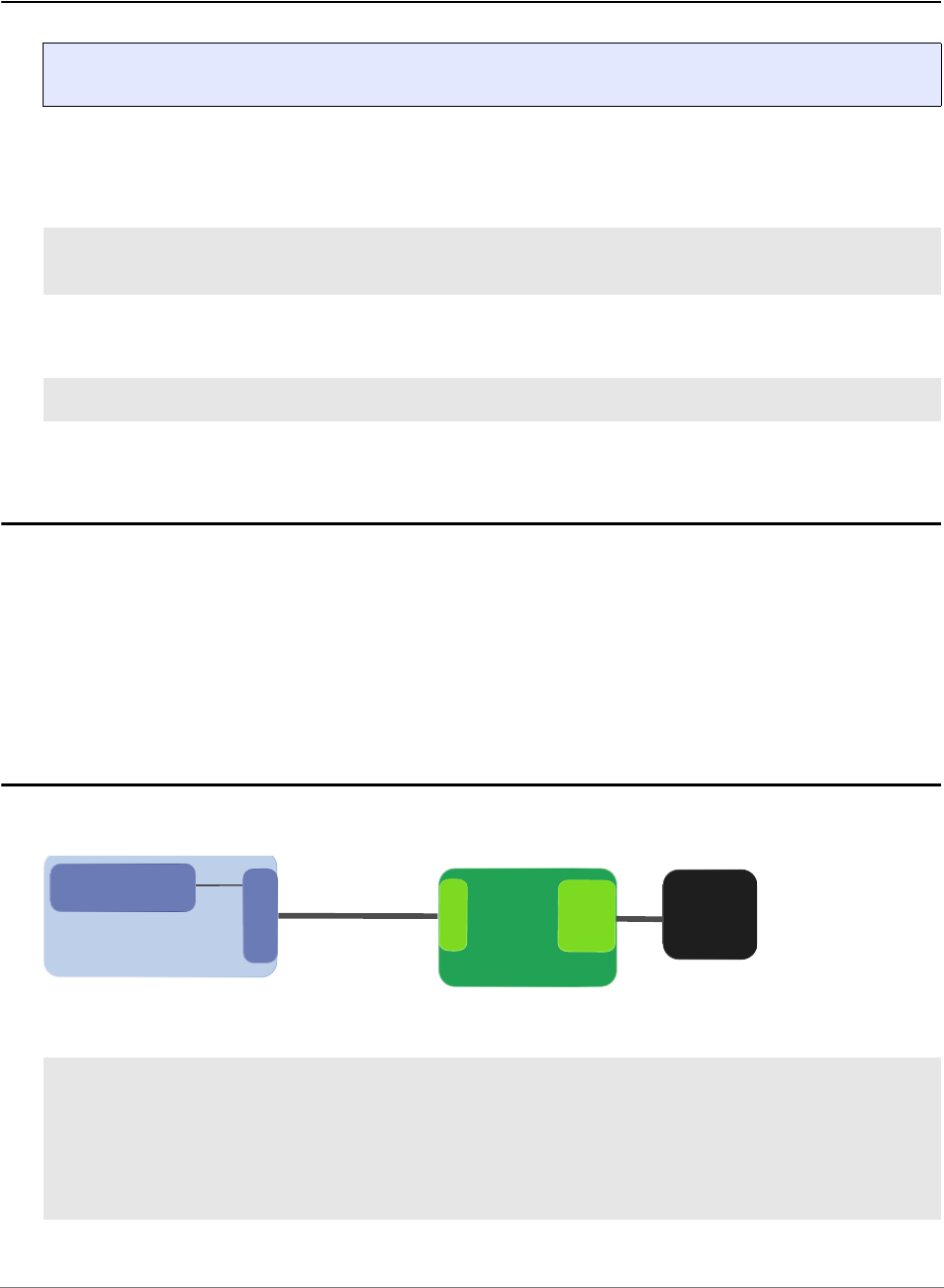
General Commands Reference Guide S | 294
©
1989-2024 Lauterbach
SYStem.CONFIG.TRANSACTORPIPENAME Set up pipe name
Defines the pipe name used to communicate with the Verilog Transactor in the RTL Simulation.
Example: Enter the transactor pipe name in TRACE32 PowerView.
Linux: Define environment variable in the context of the RTL simulation and Verilog Transactor in the shell.
SYStem.CONFIG.USB USB configuration
Intel® x86
Using the SYStem.CONFIG.USB command group, you can configure a TRACE32 system for debugging
via the USB protocol.
For more information, see “Debugging via USB User´s Guide” (usbdebug_user.pdf).
SYStem.CONFIG.XCP XCP specific settings
The SYStem.CONFIG.XCP command group allows to set up and configure debugging over XCP.
The command group is available after XCP0 has been selected as debug port.
Format: SYStem.CONFIG.TRANSACTORPIPENAME <file>
SYStem.CONFIG.DEBUGPORT VerilogTransactor0
SYStem.CONFIG.TRANSACTORPIPENAME "/tmp/t32verilog_actuator_user"
> export T32VERILOGTRANSACTORPIPE=/tmp/t32verilog_actuator_user
;optional step: open the SYStem.CONFIG.state dialog showing the DebugPort
;tab
SYStem.CONFIG.state /DebugPort
;selecting the XCP back-end activates the SYStem.CONFIG XCP commands
SYStem.CONFIG.DEBUGPORT XCP0
Host Computer
TRACE32
TCP
3rd-Party System
JTAG
DAP
TCP
CPU
XCP over TCP
(Network Cable)


General Commands Reference Guide S | 296
©
1989-2024 Lauterbach
SYStem.CPU Select CPU
Tells TRACE32 the exact CPU type used on your target. This is required to get the matching PER file and
other CPU specific settings (e.g. predefined settings for on-chip FLASH). Asterisks (*) can be used as
wildcard characters to list all CPUs of an architecture or just the ones matching the filter criterion.
Examples:
See also
■ SYStem.state ■ PER.view ❏ CPUFAMILY() ❏ SYStem.CPU()
▲ ’Release Information’ in ’Legacy Release History’
Format: SYStem.CPU <cpu>
SYStem.CPU ARM940T ;select the CPU type ARM940T
;... your code
SYStem.Up ;start the debugger
NOTE: SYStem.CPU used together with an asterisk in a PRACTICE script (*.cmm)
causes the script to stop, and the SYStem.CPU window is displayed until you
have made a selection.
SYStem.CPU * ;list the CPUs of an architecture
SYStem.CPU *ultra* ;list the CPUs of an architecture matching the
;filter criterion

General Commands Reference Guide S | 297
©
1989-2024 Lauterbach
SYStem.CpuAccess Run-time memory access (intrusive)
Default: Denied.
Configures how memory access is handled during run-time.
See also
■ SYStem.state
Format: SYStem.CpuAccess <sub_cmd> (deprecated)
<sub_cmd>: Enable (deprecated)
Use SYStem.MemAccess StopAndGo instead.
Denied (deprecated)
There is no need to use a successor command (default setting).
Nonstop (deprecated)
Use SYStem.CpuBreak Denied instead.
Enable Allow intrusive run-time memory access.
Denied Lock intrusive run-time memory access.
Nonstop Lock all features of the debugger that affect the run-time behavior.

General Commands Reference Guide S | 298
©
1989-2024 Lauterbach
SYStem.CpuBreak Master control to deny stopping the target (long stop)
Default: Enable.
See also
■ SYStem.state
Format: SYStem.CpuBreak [<mode>]
<mode>: Enable | Denied
Enable Allows stopping the target.
Denied Denies stopping the target. This includes manual stops and stop
breakpoints. However, short stops, such as spot breakpoints, may still be
allowed.
SYStem.CpuBreak Denied can be used to protect a target system which
does not tolerate that the program execution is stopped for an extended
period of time; for example, a motor controller which could damage the
motor if the motor control software is stopped.
For more information, see SYStem.CpuSpot, SYStem.MemAccess.

General Commands Reference Guide S | 299
©
1989-2024 Lauterbach
SYStem.CpuSpot Master control to deny spotting the target (short stop)
Default: Enable.
Spotting is an intrusive way to transfer data periodically or on certain events from the target system to the
debugger. As a result, the program is not running in real-time anymore. For more information, see
SYStem.CpuBreak and SYStem.MemAccess.
See also
■ SYStem.state
SYStem.DCI DCI configuration
Intel® x86
The Intel
®
Direct Connect Interface (DCI) allows debugging and tracing of Intel
®
targets using the USB3 port
of the target system.
The SYStem.DCI command group allows to configure target properties as well as TRACE32 hardware
dedicated for the use with DCI.
For more information, see “Debugging via Intel® DCI User´s Guide” (dci_intel_user.pdf).
See also
■ SYStem
Format: SYStem.CpuSpot [<mode>]
<mode>: Enable | Denied | Target | SINGLE
Enable Allows spotting the target.
Denied Denies spotting the target.
Stopping the target may still be allowed.
Target Allows spotting the target controlled by the target.
This allows target-stopped FDX and TERM communication.
All other spots are denied.
SINGLE Allows single spots triggered by a command.
This includes spotting for changing the breakpoint configuration and the
SNOOPer.PC command.
This setting also allows target-stopped FDX and TERM communication.
All other spots are denied.

General Commands Reference Guide S | 300
©
1989-2024 Lauterbach
SYStem.DETECT Detect target system resources
[System Detection Wizard]
Format: SYStem.DETECT <type>
<type>: state
BASECPU
CPU
DaisyChain
CoreSightTrace
DAP
IDCode
JtagClock
PortSHaRing
state Opens the System Detection Wizard which allows a step-by-step
investigation of the entire JTAG chain. It displays all found devices and
suggests a CPU and the corresponding multi-core settings for each
found device. The user can choose the desired core, any valid multi-core
configuration will be applied.
BASECPU Detects and selects the appropriate CPU and multi-core configuration for
the first device in the JTAG chain. CPU detection is only based on the
JTAG ID code, no further ID registers are read from the device.
CPU Detects and selects the appropriate CPU and multi-core configuration for
the first device in the JTAG chain. The command will investigate the
entire device for an exact detection.
If supported for your architecture, you can use SYStem.CPU AUTO
instead.
DaisyChain Scans your JTAG chain and prints details to the AREA window.
See example.
CoreSightTrace Tries to detect the ARM CoreSight Trace topology and prints details to
the AREA window.
DAP Identifies the types of access ports of the DAP.
In addition, the SYStem.DETECT.DAP command inspects the ROM
tables, if available, to discover any CoreSight components and their
access addresses.
The result is displayed in the form of a list in the SYStem.DETECT.DAP
window.
SHOWChain Scans the JTAG chain and show details in a separate window.
In this window (SYStem.DETECT SHOWChain) you can double-click on
a CPU core to set the values IRPOST, IRPRE, DRPOST and DRPRE in
window SYSTEM.CONFIG state /Jtag accordingly.

General Commands Reference Guide S | 301
©
1989-2024 Lauterbach
IDCode Detects the ID codes of all JTAG-TAP controllers in the JTAG chain and
stores them internally, i.e. the result is not printed to the AREA window. In
order to access the result use the following functions:
• IDCODENUMBER() returns the number of detected TAP
controllers.
• IDCODE() returns the IDCODE of the n-th TAP controller
Example: PRINT IDCODE(0) prints 0x100034B1, if the first core in the
JTAG chain is an ARC700.
JtagClock Determines the maximum JTAG Frequency by polling the BYPASS register.
This only reflects the quality of the electrical connection and the speed the
BYPASS register path. The function EVAL() retrieves the result of the
command in Hertz. This command may heavily confuse all devices attached
to the JTAG chain.
PortSHaRing Determines if the debug port is shared with a 3rd-party tool. In a PRACTICE
script, the result can be obtained by the PORTSHARING() function.
NOTE: The availability of the SYStem.DETECT types are dependent on the archi-
tecture and the debug port protocol, so they may not be available for all
architectures and configurations.
NOTE: SYStem.DETECT may apply a Power-on Reset to your system and always
switches the debug system to Down-State (see SYStem.Mode Down).

General Commands Reference Guide S | 302
©
1989-2024 Lauterbach
The System Detection Wizard
The System Detection Wizard is still under construction. It currently supports only the following
architectures: ARM/Cortex, MIPS, TriCore.
Example for the ARM architecture:
Before TRACE32 can check your target configuration it needs to know how the TRACE32 debugger is
connected to the target (here for example via JTAG).
Click Continue to confirm that the connection details are valid.
SYStem.DETECT state ; open a System Detection Wizard

General Commands Reference Guide S | 303
©
1989-2024 Lauterbach
TRACE32 runs the system detection and display the results.
If several cores are detected, you can choose which core should be controlled by the current TRACE32
instance by pushing the Set <core> button. Here for example “Device 1: Set ARM9EJ”.
The Save Configuration button allows you to store the chosen settings to a file.

General Commands Reference Guide S | 304
©
1989-2024 Lauterbach
Daisy-Chain Detection via the TRACE32 AREA Window
The result of the daisy-chain detection is displayed in the AREA window. TRACE32 also displays the
commands that are required for a correct daisy-chain setup (see blue bar). Just copy these commands to
your script, separate them by space and you are done.
Please be aware that TRACE32 can only generate the commands for the daisy-chain setup if it knows the ID
codes for the cores on your target (see picture below).
See also
■ SYStem.state ❏ IDCODE()
SYStem.DLLCommand Custom DLL connection to target
Debugger MIPS, V24 monitor with DLL
See also
■ SYStem.state
AREA.view ; open a TRACE32 AREA window
SYStem.DETECT.DaisyChain ; run TRACE32 daisy-chain detection
Format: SYStem.DLLCommand

General Commands Reference Guide S | 305
©
1989-2024 Lauterbach
SYStem.InfineonDAS Configure the InfineonDAS debug port
Tr i Co r e , G T M
The SYStem.InfineonDAS command group allows to configure the back-end for DAS. The command group
is available after InfineonDAS0 has been selected as debug port.
For more information, see “Debugging via Infineon DAS Server” (backend_das.pdf).
See also
■ SYStem
;optional step: open the SYStem.CONFIG.state dialog showing the DebugPort
;tab
SYStem.CONFIG.state /DebugPort
;selecting the DAS back-end activates the SYStem.InfineonDAS commands
SYStem.CONFIG.DEBUGPORT InfineonDAS0

General Commands Reference Guide S | 306
©
1989-2024 Lauterbach
SYStem.IRISconfig IRIS-specific setups
Virtual targets only: IRIS
The SYStem.IRISconfig command group is used to define IRIS-specific setups for debugging and tracing.
See also
■ SYStem.CADIconfig ■ SYStem.state
SYStem.IRISconfig.RemoteServer Define connection to IRIS server
Virtual targets only: IRIS
Defines connection parameters to IRIS server.
Format: SYStem.IRISconfig.RemoteServer [<ip> <port>]

General Commands Reference Guide S | 307
©
1989-2024 Lauterbach
SYStem.JtagClock Define JTAG frequency
Selects the JTAG port frequency (TCK) used by the debugger to communicate with the processor. The
frequency affects e.g. the download speed. It could be required to reduce the JTAG frequency if there are
buffers, additional loads or high capacities on the JTAG lines or if VTREF is very low. A very high frequency
will not work on all systems and will result in an erroneous data transfer. Therefore we recommend to use
the default setting if possible.
See also
■ SYStem.state ❏ SYStem.JtagClock()
▲ ’Release Information’ in ’Legacy Release History’
Format: SYStem.JtagClock <frequency>

General Commands Reference Guide S | 308
©
1989-2024 Lauterbach
SYStem.LOG Log read and write accesses to the target
[Example]
Using the SYStem.LOG command group, you can record the read and write accesses TRACE32 performs
to the target hardware. For example, the SYStem.LOG command group can be used to diagnose why
errors like “debug port fail”, “bus error”, etc. occurred. By default, logging stops after an error has occurred
(see SYStem.LOG.StopOnError).
The read and write accesses can be displayed in the SYStem.LOG.List window. In addition, they can be
recorded in a system log file with an unlimited file size. The log entries are recorded in plain text format, and
the read and write accesses are converted to Data.Set commands. This way it is possible to re-run the
system log in a TRACE32 Instruction Set Simulator.
The system log records all TRACE32 debugger accesses to the target. Examples of accesses that cannot
be logged include:
• Accesses via JTAG API
• Accesses initiated by the TERM command
• Accesses initiated by the SNOOPer command
For configuring a system log, use the TRACE32 command line, a PRACTICE script (*.cmm), or the
SYStem.LOG.state window:

General Commands Reference Guide S | 309
©
1989-2024 Lauterbach
Example:
See also
■ SYStem.LOG.CLEAR ■ SYStem.LOG.CLOSE ■ SYStem.LOG.Init ■ SYStem.LOG.List
■ SYStem.LOG.Mode ■ SYStem.LOG.OFF ■ SYStem.LOG.ON ■ SYStem.LOG.OPEN
■ SYStem.LOG.RESet ■ SYStem.LOG.Set ■ SYStem.LOG.SIZE ■ SYStem.LOG.state
■ SYStem.LOG.StopOnError ■ SYStem.state ■ SLTrace ■ LOG
SYStem.LOG.CLEAR Clear the ‘SYStem.LOG.List’ window
Clears and immediately re-populates the list in the SYStem.LOG.List window with new system log entries -
same as if you are running the commands SYStem.LOG.Init and SYStem.LOG.ON in rapid succession.
SYStem.LOG.CLEAR is the command behind the Clear button in the SYStem.LOG.List window.
See also
■ SYStem.LOG ■ SYStem.LOG.Init ■ SYStem.LOG.state
SYStem.LOG.state ;optional: open the configuration window
SYStem.LOG.RESet ;use default configuration of system log
SYStem.LOG.OPEN ~~\sys.log ;open a system log file for writing
SYStem.LOG.List ;display the accesses to the target
;log the read and write accesses to the target
List.auto
Step.single
SYStem.LOG.CLOSE ;close the system log file for writing
Format: SYStem.LOG.CLEAR

General Commands Reference Guide S | 310
©
1989-2024 Lauterbach
SYStem.LOG.CLOSE Close the system log file
Closes the active system log file. Any further read and write accesses are not recorded in the system log file.
You can now open the file in an EDIT or TYPE window or in another application.
Example: Using the DO command, you can also re-run the system log in a TRACE32 Instruction Set
Simulator. You do not need to rename the file extension to cmm, the extension for PRACTICE scripts; you
can keep the file extension log.
See also
■ SYStem.LOG ■ SYStem.LOG.OPEN ■ SYStem.LOG.state
SYStem.LOG.Init Clear the "SYStem.LOG.List" window
Clears the system log entries displayed in the SYStem.LOG.List window. The SYStem.LOG.Init command
has no impact on the system log file.
Since the SYStem.LOG.List window itself continues to log the target, the list in the window may be
immediately re-populated after clearing.
To prevent the list in the SYStem.LOG.List window from being re-populated, run these commands:
See also
■ SYStem.LOG ■ SYStem.LOG.CLEAR ■ SYStem.LOG.state
Format: SYStem.LOG.CLOSE
...
SYStem.LOG.CLOSE ;close the system log file for writing
PEDIT ~~\sys.log ;open log file as a PRACTICE script
Format: SYStem.LOG.Init
SYStem.LOG.OFF
SYStem.LOG.Init

General Commands Reference Guide S | 311
©
1989-2024 Lauterbach
SYStem.LOG.List Log the accesses made by TRACE32
Displays all types of target accesses made by TRACE32.
Description of Toolbar Buttons in the SYStem.LOG.List Window
Description of Columns in the SYStem.LOG.List Window
See also
■ SYStem.LOG ■ SYStem.LOG.state
▲ ’Release Information’ in ’Legacy Release History’
Format: SYStem.LOG.List
Data.LOG (deprecated)
Setup Opens the SYStem.LOG.state window.
On Starts/resumes logging - same as SYStem.LOG.ON.
Off Pauses logging - same as SYStem.LOG.OFF.
Clear Clears and immediately re-populates the list with new system log entries -
same as if you are running the commands SYStem.LOG.Init and
SYStem.LOG.ON in rapid succession.
op Type of target access.
address Access class and address where TRACE32 has accessed the target.
width The bus width used by TRACE32.
Example: The value 4. indicates that TRACE32 performs 32-bit read or write
accesses.
data Data written or read. Only the first 8 bytes are displayed in the
SYStem.LOG.List window.
time Absolute timestamps in relation to ZERO.
xtime Execution time.

General Commands Reference Guide S | 312
©
1989-2024 Lauterbach
SYStem.LOG.Mode Set logging mode
Sets the degree of detail with which the read and write accesses are recorded in the system log file.
See also
■ SYStem.LOG ■ SYStem.LOG.state
Format: SYStem.LOG.Mode <logging_mode>
<logging_
mode>:
Compact ON | OFF
Source ON | OFF
NoTime ON | OFF
Compact
(default: OFF)
• OFF: Access addresses and data are included in the system log
file.
• ON: Access addresses are logged, but data is not logged.
Source
(default: OFF)
• OFF: The source of accesses such as ETM, HTM, etc. is not
logged.
• ON: Information about which component has accessed the target
is included in the system log file.
NoTime
(default: OFF)
• OFF: Timing information is included in the system log file; see time
and xtime columns of the SYStem.LOG.List window.
• ON: Timing information is not logged.
NoTime ON is useful, for example, if you want to compare two
versions of a system log file.

General Commands Reference Guide S | 313
©
1989-2024 Lauterbach
SYStem.LOG.OFF Pause logging
Temporarily deactivates logging, i.e. the read and write accesses are no longer logged. However, the system
log file remains operational. Logging can be resumed with SYStem.LOG.ON.
Example:
See also
■ SYStem.LOG.ON ■ SYStem.LOG ■ SYStem.LOG.state
SYStem.LOG.ON Resume logging
Logs all read and write accesses you have selected with SYStem.LOG.Set. The SYStem.LOG.ON
command can be used after the system log has been temporarily deactivated with the command
SYStem.LOG.OFF.
See also
■ SYStem.LOG.OFF ■ SYStem.LOG ■ SYStem.LOG.state
Format: SYStem.LOG.OFF
SYStem.LOG.OPEN ~~\sys.log ;open a system log file for writing
;… ;log read and write accesses
;…
SYStem.LOG.OFF ;temporarily deactivate logging
;… ;accesses are no longer logged
SYStem.LOG.ON ;resume logging
;… ;accesses are logged again
;…
SYStem.LOG.CLOSE ;close system log file and terminate logging
Format: SYStem.LOG.ON

General Commands Reference Guide S | 314
©
1989-2024 Lauterbach
SYStem.LOG.OPEN Open a system log file
Generates a new system log file for logging read and write accesses and opens it for writing. The number of
logged read and write accesses is unlimited. If a file with the same name already exists, it will be overwritten.
Example:
The path prefix ~~ expands to the TRACE32 system directory, by default C:\t32.
See also
■ SYStem.LOG ■ SYStem.LOG.CLOSE ■ SYStem.LOG.state
SYStem.LOG.RESet Reset configuration of system log to defaults
Resets all commands of the SYStem.LOG command group to their defaults. You can view the result in the
SYStem.LOG.state window.
See also
■ SYStem.LOG ■ SYStem.LOG.state
Format: SYStem.LOG.OPEN <file>
<file> The default extension for <file> is *.log.
SYStem.LOG.OPEN ~~\sys.log ;open a system log file
;…
;…
SYStem.LOG.CLOSE ;close file and terminate logging
Format: SYStem.LOG.RESet

General Commands Reference Guide S | 315
©
1989-2024 Lauterbach
SYStem.LOG.Set Select the TRACE32 accesses to be logged
Allows you to select the TRACE32 accesses you want to record in SYStem.LOG.List.
Format: SYStem.LOG.Set <setting>
<setting>: Polling ON | OFF
MemoryRead ON | OFF
MemoryWrite ON | OFF
RegisterRead ON | OFF
RegisterWrite ON | OFF
ComponentRead ON | OFF
ComponentWrite ON | OFF
VMaccess ON | OFF
TRANSlation ON | OFF
TRACE ON | OFF
REMOTEAPI ON | OFF
OS ON | OFF
ERROR ON | OFF
<setting> OFF This <setting> is omitted from the system log file.
<setting> ON This <setting> is included in the system log file.
ComponentRead Read accesses to a debug component.
ComponentWrite Write accesses.
ERROR
• ON: All errors are included in the system log file.
• OFF: Logs only errors of the read and write accesses that are set
to ON.
MemoryRead Memory read accesses.
MemoryWrite Memory write accesses.
OS Accesses to the operating system (OS).
Polling Polling of the CPU. The polling mode can be set with SYStem.POLLING.
RegisterRead Register read accesses.
RegisterWrite Register write accesses.
REMOTEAPI Accesses via the TRACE32 Remote API. See also “API for Remote
Control and JTAG Access in C” (api_remote_c.pdf).
TRACE Accesses to the trace data streaming.

General Commands Reference Guide S | 316
©
1989-2024 Lauterbach
See also
■ SYStem.LOG ■ SYStem.LOG.state
▲ ’Release Information’ in ’Legacy Release History’
SYStem.LOG.SIZE Define number of lines in the ‘SYStem.LOG.List’ window
Default: 64.
Defines the number of lines displayed in the SYStem.LOG.List window. The displayed lines reflect the most
recent read and write accesses to the target hardware. The <lines> setting does not affect the file size.
See also
■ SYStem.LOG ■ SYStem.LOG.state
TRANSlation
• ON: Display valid address translations and translation failures in
the system log file. Currently only the logical address is displayed.
• OFF: Include only translation failures in the system log file.
VMaccess If the option is enabled, any read or write access to addresses with the
access class VM: or AVM: will be recorded in the SYStem.LOG.List
window.
Format: SYStem.LOG.SIZE <lines>

General Commands Reference Guide S | 317
©
1989-2024 Lauterbach
SYStem.LOG.state Open configuration window of system log
Opens the SYStem.LOG.state window, where you can configure a system log for recording read and write
accesses to the target hardware.
See also
■ SYStem.LOG ■ SYStem.LOG.CLEAR ■ SYStem.LOG.CLOSE ■ SYStem.LOG.Init
■ SYStem.LOG.List ■ SYStem.LOG.Mode ■ SYStem.LOG.OFF ■ SYStem.LOG.ON
■ SYStem.LOG.OPEN ■ SYStem.LOG.RESet ■ SYStem.LOG.Set ■ SYStem.LOG.SIZE
■ SYStem.LOG.StopOnError ■ SLTrace
Format: SYStem.LOG.state
A Only the information of selected options is displayed in the SYStem.LOG.List window and recorded
in the system log file.
For descriptions of the individual options, see SYStem.LOG.Set.
B To open a system log file, do one of the following:
• Click the folder icon and navigate to the file you want to use.
• Type path and file name into the OPEN text box. Then press Enter.
The TRACE32 message line displays that the file is now open for recording log entries.
To close the system log file:
• Clear the content from the OPEN text box. Then press Enter.
The TRACE32 message line displays that the file is now closed.
C For descriptions of the commands in the SYStem.LOG.state window, refer to the SYStem.LOG.*
commands in this section.
Example: For information about the List button, see SYStem.LOG.List.
B
C
A

General Commands Reference Guide S | 318
©
1989-2024 Lauterbach
SYStem.LOG.StopOnError Stop logging on error
Defines the logging behavior after an error has occurred.
See also
■ SYStem.LOG ■ SYStem.LOG.state
SYStem.MCDCommand Send command to MCD server
Virtual targets only: MCD
SYStem.MCDCommand <command> sends via the MCD API call mcd_execute_command_f() the
<command> as ASCII character string to the MCD server. It is not necessary to enclose the command with
quotation marks. All quotations marks within <command> will be sent as such to the MCD server. The
answer from the MCD server on this command can have a maximum of 100 characters and can be read out
by SYStem.MCDCommand.ResultString().
See also
■ SYStem.state
Format: SYStem.LOG.StopOnError ON | OFF
ON
(default)
TRACE32 automatically runs the command SYStem.LOG.OFF to stop
logging after an error, such as a bus error, has occurred.
OFF Logging continues after an error has occurred.
NOTE: The system log file remains open for writing.
• To continue logging, click Start in the SYStem.LOG.List window or run
SYStem.LOG.ON.
• To close the system log file, run SYStem.LOG.CLOSE.
Format: SYStem.MCDCommand <command>

General Commands Reference Guide S | 319
©
1989-2024 Lauterbach
SYStem.MCDconfig Send configuration to MCD server
Virtual targets only: MCD
SYStem.MCDCommand <srv.cfg> will send <srv.cfg> as ASCII character string within the parameter
config_string of mcd_open_server_f() towards the MCD server. It is not necessary to enclose
<srv.cfg> with quotation marks. All quotations marks in <srv.cfg> will be sent to the MCD server.
See also
■ SYStem.state
Format: SYStem.MCDconfig <srv.cfg>

General Commands Reference Guide S | 320
©
1989-2024 Lauterbach
SYStem.MemAccess Select run-time memory access method
The debugger can read and write the target memory while the CPU is executing the program.
See also
■ SYStem.state
▲ ’Release Information’ in ’Legacy Release History’
Format: SYStem.MemAccess <mode>
<mode>: Enable | Denied | StopAndGo | <cpu_specific> | <interface_specific>
Enable
CPU (deprecated)
Is used to activate the memory access while the CPU is running on the
TRACE32 Instruction Set Simulator and on debuggers which do not have
a fixed name for the memory access method.
Denied Memory access during program execution to target is disabled.
StopAndGo Temporarily halts the core(s) to perform the memory access. Each stop
takes some time depending on the speed of the JTAG port, the number of
the assigned cores, and the operations that should be performed.
<cpu_specific> Depending on the target processor, there may exist means to access
processor / target memory while the processor is running. Examples are
DAP, AHB or AXI for ARM processors, NEXUS or SAP for Power
Architecture, and so on. Refer to processor architecture manuals for
details.
<interface_specific> Depending on the debug interface in use, there may exist means to
access processor / target memory while the processor is running.
Example: XCP.

General Commands Reference Guide S | 321
©
1989-2024 Lauterbach
SYStem.Mode Select mode
Configures how the debugger connects to the target and how the target is handled. Please refer to the
description of this command in your Processor Architecture Manual for more information.
See also
■ SYStem.state
▲ ’Release Information’ in ’Legacy Release History’
SYStem.Option Special setup
[SYStem.state window > Option]
The <options> of SYStem.Option are used to control special features of the debugger or to configure the
target. It is recommended to execute the SYStem.Option commands before the emulation is activated by a
SYStem.Up or SYStem.Mode command.
See also
■ SYStem.Option.IMASKASM ■ SYStem.Option.IMASKHLL
■ SYStem.Option.MACHINESPACES ■ SYStem.Option.MMUSPACES
■ SYStem.Option.ZoneSPACES ■ SYStem.state
▲ ’Release Information’ in ’Legacy Release History’
Format: SYStem.Mode [<mode>]
SYStem.<mode> (as an alternative)
<mode>: StandBy
Down
Attach
NoDebug
Go
Up
Prepare
Format: SYStem.Option <option> [ON | OFF]
<option> Mostly architecture specific. For descriptions of the options, refer to the
Processor Architecture Manuals.
NOTE: Some of the commands toggle between the options ON and OFF if they are
invoked without parameters.

General Commands Reference Guide S | 322
©
1989-2024 Lauterbach
SYStem.Option.IMASKASM Disable interrupts while single stepping
Default: OFF.
If enabled, the interrupt mask bits of the CPU will be set during assembler single-step operations. The
interrupt routine is not executed during single-step operations. After single step the interrupt mask bits are
restored to the value before the step.
See also
■ SYStem.Option
SYStem.Option.IMASKHLL Disable interrupts while HLL single stepping
Default: OFF.
If enabled, the interrupt mask bits of the cpu will be set during HLL single-step operations. The interrupt
routine is not executed during single-step operations. After single step the interrupt mask bits are restored to
the value before the step.
See also
■ SYStem.Option
SYStem.Option.MACHINESPACES Address extension for guest OSes
ARM and Intel® x86
Default: OFF
Enables the TRACE32 support for debugging virtualized systems. Virtualized systems are systems running
under the control of a hypervisor.
After loading a Hypervisor Awareness, TRACE32 is able to access the context of each guest machine. Both
currently active and currently inactive guest machines can be debugged.
Format: SYStem.Option.IMASKASM [ON | OFF]
Format: SYStem.Option.IMASKHLL [ON | OFF]
Format: SYStem.Option.MACHINESPACES [ON | OFF]

General Commands Reference Guide S | 323
©
1989-2024 Lauterbach
If SYStem.Option.MACHINESPACES is enabled, addresses are extended with an identifier called machine
ID. The machine ID clearly specifies to which host or guest machine the address belongs.
See also
■ SYStem.Option
SYStem.Option.MMUSPACES Separate address spaces by space IDs
Default: OFF.
Enables the use of space IDs for logical addresses to support multiple address spaces.
For an explanation of the TRACE32 concept of address spaces (zone spaces, MMU spaces, and machine
spaces), see “TRACE32 Concepts” (trace32_concepts.pdf).
NOTE: For architecture-specific information about the command, refer to the Processor
Architecture Manual.
Format: SYStem.Option.MMUSPACES [ON | OFF]
SYStem.Option.MMUspaces [ON | OFF] (deprecated)
SYStem.Option.MMU [ON | OFF] (deprecated)
NOTE: SYStem.Option.MMUSPACES should not be set to ON if only one translation
table is used on the target.
If a debug session requires space IDs, you must observe the following
sequence of steps:
1. Activate SYStem.Option.MMUSPACES.
2. Load the symbols with Data.LOAD.
Otherwise, the internal symbol database of TRACE32 may become
inconsistent.
General Commands Reference Guide S | 324
©
1989-2024 Lauterbach
Examples:
See also
■ SYStem.Option
SYStem.Option.ZoneSPACES Enable symbol management for zones
Default: OFF. Not supported for all core architectures.
For CPUs which have several operation modes with individual MMU translations and register sets, the
SYStem.Option ZoneSPACES command allows to load separate symbol sets for these CPU modes.
Within TRACE32, such CPU modes are referred to as zones. Addresses and symbols belonging to a certain
CPU mode are identified by their access class specifier.
If a symbol is referenced by name, the associated access class of its zone will be used automatically, so that
the memory access is done within the correct CPU mode context. As a result, the symbol’s logical address
will be translated to the physical address with the correct MMU translation table.
See also
■ SYStem.Option
;Dump logical address 0xC00208A belonging to memory space with
;space ID 0x012A:
Data.dump D:0x012A:0xC00208A
;Dump logical address 0xC00208A belonging to memory space with
;space ID 0x0203:
Data.dump D:0x0203:0xC00208A
Format: SYStem.Option.ZoneSPACES [ON | OFF]
OFF TRACE32 does not separate symbols by access class.
ON Separate symbol sets can be loaded for each zone, even with
overlapping address ranges. Loaded symbols are specific to one of the
CPU zones.
NOTE: For architecture-specific information about the command, refer to the Processor
Architecture Manual.

General Commands Reference Guide S | 325
©
1989-2024 Lauterbach
SYStem.PAUSE Pause the execution of operations
Pauses the execution of any operation of the debugger including semihosting, status polling, and APIs. The
command cannot be interrupted or canceled. The passed option only takes effect if a back-end with virtual
connection to an RTL emulation/simulation is used, e.g. GTL.
See also
■ SYStem.state ■ WAIT
Format: SYStem.PAUSE <time> [/<option>]
<option>: Target | Host
<time>
• The pause time of Host is typically measured in milliseconds, e.g.
100ms
• The pause time of Target is typically measured in microseconds,
e.g. 10us
• Without Target or Host: The used time base depends on
SYStem.VirtualTiming.PauseinTargetTime.
Host Host clock is used as time base.
Target Emulation clock is used as time base.

General Commands Reference Guide S | 326
©
1989-2024 Lauterbach
SYStem.POLLING Polling mode of CPU
When the CPU is running, the debug driver can poll the CPUs state in the background to speed up
operations where a fast break detection is preferred. Features that can be improved by a fast break
detection are:
• CPU break from PodBus Trigger, if the CPU has no dedicated break in line
• Any communication that is based to spot break points e.g. TERM, FDX
• Break triggered actions like Data.EPILOG, Data.TIMER
• Precision of the runtime counter if the CPU has no dedicated break in line
If the poll rate is high the system is more sensitive to disturbances.
When the CPU is stopped, the debug driver can poll the CPUs state in the background to observe for
exceptional events caused by watch-dogs or other CPUs.
Format: SYStem.POLLING <run_mode> <stopped_mode>
<run_mode>: CONTinuous
DEFault
FAST
OFF
SLOW
<stopped_
mode>:
DEFault
OFF
SIGnals
CONTinuous Polling with maximum frequency.
FAST Polling with interval of 1 ms.
OFF No polling at all, to prevent from disturbance.
SLOW Normal polling with interval of SETUP.UpdateRATE, increase RTCK time-
out to hide short power down/sleep states of the CPU.
DEFault Polling with interval of SETUP.UpdateRATE.
NOTE: The minium polling interval for timing measurement tasks, e.g. RunTime, is
1 ms, any lower settings are ignored.

General Commands Reference Guide S | 327
©
1989-2024 Lauterbach
For transactor based solutions those polling can slow down the debug session, therefore it’s possible to turn
it off.
See also
■ SYStem.state ■ SETUP.UpdateRATE
▲ ’Release Information’ in ’Legacy Release History’
SYStem.PORT Configure external communication interface
This command is used to configure an external communication interface:
• Between TRACE32 and a monitor program running on the target.
• Between TRACE32 and a debug agent running on the target.
Both serial and TCP/IP are supported.
Examples:
See also
■ SYStem.state
SIGnals Polling of signals as RESET only
OFF No polling at all, to prevent from disturbance.
DEFault Polling with interval of SETUP.UpdateRATE.
Format: SYStem.PORT <mode>
<mode>: COM<x> <settings>
<ip>:<port>
<x> COM port number, e.g. COM1, COM2
<settings> The <settings> for the communication interfaces depend on the host
operating system.
SYStem.PORT COM1 baud=9600 ; configure COM1 as external
; communication interface
SYStem.PORT 10.1.2.99:2345 ; configure TCP/IP as external
; communication interface

General Commands Reference Guide S | 328
©
1989-2024 Lauterbach
SYStem.RESet Reset configuration
Resets all debug system settings (such as SYStem.CPU, SYStem.JtagClock) to their default values. After
this switches to the SYStem.Mode Down state.
See also
■ SYStem.state ■ RESet
▲ ’Release Information’ in ’Legacy Release History’
SYStem.RESetOut Reset peripherals
Triggers the CPU RESET command, which initializes the peripherals. This command is not available on all
probes.
Example:
See also
■ SYStem.state
▲ ’Release Information’ in ’Legacy Release History’
SYStem.RESetTarget Release target reset
A target reset is performed and then released. On most targets, SYStem.RESetTarget is similar to
SYStem.Up and Register.RESet. On virtual platforms usually activates a target platform reset.
See also
■ SYStem.state
▲ ’Release Information’ in ’Legacy Release History’
Format: SYStem.RESet
Format: SYStem.RESetOut
SYStem.RESetOut ; Initialize peripherals
Format: SYStem.RESetTarget
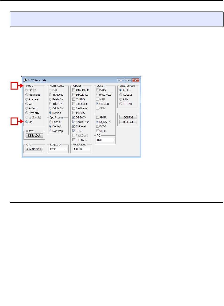
General Commands Reference Guide S | 329
©
1989-2024 Lauterbach
SYStem.state Display SYStem.state window
Opens a SYStem.state window displaying all probe setup parameters. You can also open the
SYStem.state window by double-clicking the System field in the state line of the TRACE32 main window.
All modes can be selected and altered by clicking the appropriate buttons, options, etc. within the
SYStem.state window.
The SYStem.state window is highly target-dependent; example of a SYStem.state window:
See also
■ SYStem.BdmClock ■ SYStem.BREAKTIMEOUT ■ SYStem.CADICommand ■ SYStem.CADIconfig
■ SYStem.CONFIG ■ SYStem.CPU ■ SYStem.CpuAccess ■ SYStem.CpuBreak
■ SYStem.CpuSpot ■ SYStem.DCI ■ SYStem.DETECT ■ SYStem.DLLCommand
■ SYStem.GTL ■ SYStem.InfineonDAS ■ SYStem.IRISconfig ■ SYStem.JtagClock
■ SYStem.LOG ■ SYStem.MCDCommand ■ SYStem.MCDconfig ■ SYStem.MemAccess
■ SYStem.Mode ■ SYStem.Option ■ SYStem.PAUSE ■ SYStem.POLLING
■ SYStem.PORT ■ SYStem.RESet ■ SYStem.RESetOut ■ SYStem.RESetTarget
■ SYStem.SNEAKPEEK ■ SYStem.TARGET ■ SYStem.TCFconfig ■ SYStem.VirtualTiming
❏ CPUIS() ❏ hardware.ICD() ❏ INTERFACE.SIM() ❏ SYStem.CPU()
❏ SYStem.Mode() ❏ SYStem.Up()
Format: SYStem.state
A For descriptions of the architecture-specific commands in the SYStem.state window, please refer to
the SYStem.* commands in your Processor Architecture Manual.
Example: For information about Up, see SYStem.Mode Up.
A
A’

General Commands Reference Guide S | 330
©
1989-2024 Lauterbach
SYStem.TARGET Set target IP name or address
Defines the OSE target IP address or name to debug. If no target is specified, TRACE32 uses a broadcast
message to find OSE targets and uses the first target found.
See also
■ SYStem.state
Format: SYStem.TARGET <target>
<target>: <ip_address> | <ip_name>

General Commands Reference Guide S | 331
©
1989-2024 Lauterbach
SYStem.VirtualTiming Modify timing constraints
The commands of the SYStem.VirtualTiming command group are used to modify time timing behavior of
the debugger when virtual debug interfaces are used, e.g. the TRACE32 Verilog Actuator or Generic
Transactor Library.
These virtual debug interfaces connect the debugger to simulations with a virtual time or extra slow
emulators. In these scenarios, PowerView commands can take a very long time to execute. Therefore, the
interaction with the target is done by PRACTICE scripts mainly, but the default timing of the debugger
software targets more a stutter-free behavior of the windows.
To modify these timings, the SYStem.VirtualTiming commands can be used. The debugger uses timeouts
to cancel polling for expected results in the debug registers of the core and for reading back hardware
acknowledge signals of the target as the RTCK signal.
The commands SYStem.VirtualTiming.TimeinTargetTime and
SYStem.VirtualTiming.PauseinTargetTime allow to couple the timing to the emulation/simulation timing.
This allows to stall the whole simulation environment without the internal timeouts expiring, but also can lead
to longer execution time of the debugger.
The command SYStem.VirtualTiming.TimeScale can be used to reduce or increase the internal timeouts
in general. In case the simulation does not respond fast enough, the timeouts need to be extended. In case
the debugger polls for an error state too long to keep the user interface responsive, the timeouts can be
reduced.
See also
■ SYStem.VirtualTiming.HardwareTimeout ■ SYStem.VirtualTiming.HardwareTimeoutScale
■ SYStem.VirtualTiming.InternalClock ■ SYStem.VirtualTiming.MaxPause
■ SYStem.VirtualTiming.MaxTimeout ■ SYStem.VirtualTiming.OperationPause
■ SYStem.VirtualTiming.PauseinTargetTime ■ SYStem.VirtualTiming.PauseScale
■ SYStem.VirtualTiming.PollingPause ■ SYStem.VirtualTiming.TimeinTargetTime
■ SYStem.VirtualTiming.TimeScale ■ SYStem.state
▲ ’Timing Adaption’ in ’Debugging via Infineon DAS Server’
▲ ’Timing Adaption’ in ’GTL Debug Back-End’
▲ ’Timing Adaption’ in ’Verilog Debug Back-End’
Format: SYStem.VirtualTiming

General Commands Reference Guide S | 332
©
1989-2024 Lauterbach
SYStem.VirtualTiming.HardwareTimeout Disable/enable hardware timeout
The debugger has a timeout that handle the maximum time to wait for an hardware signal. The timeout can
be disabled in case it doesn’t matter for the debug scenario in case error messages “no RTCK” or ”subcore
communication timeout” occur. In case the hardware timeout is necessary for the debug scenario the
debugger can enter an endless loop, in that cases the hardware timeout should be extended by
SYStem.VirtualTiming.HardwareTimeoutScale or the target should respond earlier.
Example:
See also
■ SYStem.VirtualTiming
▲ ’Timing Adaption’ in ’Debugging via Infineon DAS Server’
▲ ’Timing Adaption’ in ’GTL Debug Back-End’
▲ ’Timing Adaption’ in ’Verilog Debug Back-End’
SYStem.VirtualTiming.HardwareTimeoutScale Multiply hardware timeout
[Example]
Scales the timeout that leads to the message “subcore communication timeout” for software-only tools. The
command is implemented for the back-end GTL.
Low-level operations can have a total communication timeout to prevent the system from hanging in case of
an error. In software-only tools, this timeout can malfunction. Either the timeout appears too late and the
system seem to hang, or the timeout appears too early and the operation fails with the message “subcore
communication timeout”.
Format: SYStem.VirtualTiming.HardwareTimeout ON | OFF
ON Hardware timeout is active and used to cancel hardware operations.
OFF Hardware timeout is disabled.
SYStem.VirtualTiming.PauseinTargetTime OFF ; use host time
Format: SYStem.VirtualTiming.HardwareTimeoutScale

General Commands Reference Guide S | 333
©
1989-2024 Lauterbach
Example:
See also
■ SYStem.VirtualTiming
▲ ’Timing Adaption’ in ’Debugging via Infineon DAS Server’
▲ ’Timing Adaption’ in ’GTL Debug Back-End’
▲ ’Timing Adaption’ in ’Verilog Debug Back-End’
SYStem.VirtualTiming.InternalClock Base for artificial time calculation
Overrides the TRACE32 debug clock setting for internal timing calculation in case the interface’s debug clock
implementation is wrong in a software-only solution. A clock of 0Hz (default) will not override the debug clock
setting. The command is implemented for the back-end GTL.
Example:
See also
■ SYStem.VirtualTiming
▲ ’Timing Adaption’ in ’Debugging via Infineon DAS Server’
▲ ’Timing Adaption’ in ’GTL Debug Back-End’
▲ ’Timing Adaption’ in ’Verilog Debug Back-End’
;shrink the standard timeout by factor 10 to display the timeout earlier
SYStem.VirtualTiming.HardwareTimeoutScale 0.1
Format: SYStem.VirtualTiming.InternalClock <frequency>
; TRACE32 transfers 10Mhz setting to the interface
SYStem.JtagClock 10Mhz
; but use 100kHz for internal timing calculations
SYStem.VirtualTiming.InternalClock 100kHz

General Commands Reference Guide S | 334
©
1989-2024 Lauterbach
SYStem.VirtualTiming.MaxPause Limit pause
The debugger software contains statements to wait time, in order to give the target time to respond. The
command is used to set up the maximum time for those wait statements.
Example:
See also
■ SYStem.VirtualTiming
▲ ’Timing Adaption’ in ’Debugging via Infineon DAS Server’
▲ ’Timing Adaption’ in ’GTL Debug Back-End’
▲ ’Timing Adaption’ in ’Verilog Debug Back-End’
SYStem.VirtualTiming.MaxTimeout Override time-outs
The debugger software contains sections where a status of the target is polled for a certain time until a
conditions is met in order to finish an operation. The command is used to set up the maximum time that is
used for those sections.
Example:
See also
■ SYStem.VirtualTiming
▲ ’Timing Adaption’ in ’Debugging via Infineon DAS Server’
▲ ’Timing Adaption’ in ’GTL Debug Back-End’
▲ ’Timing Adaption’ in ’Verilog Debug Back-End’
Format: SYStem.VirtualTiming.MaxPause <time>
<time>: 10ns … 40000ms
SYStem.VirtualTiming.MaxPause 1s ; set maximum to 1 second
Format: SYStem.VirtualTiming.MaxTimeout <time>
<time>: <x>ns … <y>ms
SYStem.VirtualTiming.MaxTimeout 10s ; set maximum to 10 seconds

General Commands Reference Guide S | 335
©
1989-2024 Lauterbach
SYStem.VirtualTiming.OperationPause Insert a pause after each operation
The debug driver issue pause statements after each action e.g. shift or bus access to give the emulation
time to compute. Operation pauses will slow down the debugger and prevent from pre-bundling operations.
Example:
See also
■ SYStem.VirtualTiming
▲ ’Timing Adaption’ in ’Debugging via Infineon DAS Server’
▲ ’Timing Adaption’ in ’GTL Debug Back-End’
▲ ’Timing Adaption’ in ’Verilog Debug Back-End’
SYStem.VirtualTiming.PauseinTargetTime Set up pause time-base
The debugger software contains statements to wait time, in order to give the target time to respond. The
command specifies it the time shall elapse in virtual simulator time (ON) or real host time (OFF). When set to
ON the debugger behaves as with a real target, but become as slow as the simulation.
Example:
See also
■ SYStem.VirtualTiming
▲ ’Timing Adaption’ in ’Debugging via Infineon DAS Server’
▲ ’Timing Adaption’ in ’GTL Debug Back-End’
▲ ’Timing Adaption’ in ’Verilog Debug Back-End’
Format: SYStem.VirtualTiming.OperationPause <time>
<time>: <x>ns … <y>ms
SYStem.VirtualTiming.OperationPause 100ns ; enable pause of 100ns
Format: SYStem.VirtualTiming.PauseinTargetTime ON | OFF
ON Pause time elapses in virtual simulation time.
OFF Pause time elapses in real host time.
SYStem.VirtualTiming.PauseinTargetTime OFF ; use host time

General Commands Reference Guide S | 336
©
1989-2024 Lauterbach
SYStem.VirtualTiming.PauseScale Multiply pause with a factor
The debugger software contains statements to wait time in order to give the target time to respond. The
command scales these time in order to wait a shorter or longer time.
Example:
See also
■ SYStem.VirtualTiming
▲ ’Timing Adaption’ in ’Debugging via Infineon DAS Server’
▲ ’Timing Adaption’ in ’GTL Debug Back-End’
▲ ’Timing Adaption’ in ’Verilog Debug Back-End’
SYStem.VirtualTiming.PollingPause Advance emulation time when polling
The command is used for systems that advance the simulation time only when the debugger executes
actions on it. Usually the debugger is executing JTAG shifts all the time, but this is not efficient to let the
emulation time grow. Executing a "pause" statement at the emulation is more efficient, therefore the
command inserts "pause" statements of a certain duration when the emulation time needs to be increased,
e.g. when the core is running and the debugger waits until a breakpoint has been hit.
A smaller polling pause will speed up the debugger, but slow down the execution of the target program in the
emulation. A bigger polling pause will make the debugger less responsive, but let that emulation run faster.
Example:
See also
■ SYStem.VirtualTiming
Format: SYStem.VirtualTiming.PauseScale <factor>
SYStem.VirtualTiming.PauseScale 10. ; 10 times longer pauses
Format: SYStem.VirtualTiming.PollingPause <time>
SYStem.VirtualTiming.PollingPause 10us ; insert 10us pauses

General Commands Reference Guide S | 337
©
1989-2024 Lauterbach
SYStem.VirtualTiming.TimeinTargetTime Set up general time-base
The command specifies whether the timeout time shall elapse in virtual simulator time (ON) or real host time
(OFF). When set to ON the debugger behaves as with a real target, but become as slow as the simulation.
Example:
See also
■ SYStem.VirtualTiming
▲ ’Timing Adaption’ in ’Debugging via Infineon DAS Server’
▲ ’Timing Adaption’ in ’GTL Debug Back-End’
▲ ’Timing Adaption’ in ’Verilog Debug Back-End’
Format: SYStem.VirtualTiming.TimeinTargetTime ON | OFF
ON Use virtual target time to elapse time-outs
OFF Use real host time to elapse time-outs
SYStem.VirtualTiming.TimeinTargetTime ON ; time-outs elapse time-outs

General Commands Reference Guide S | 338
©
1989-2024 Lauterbach
SYStem.VirtualTiming.TimeScale Multiply time-base with a factor
The command scales pauses and time-outs in general.
Example 1:
Example 2:
See also
■ SYStem.VirtualTiming
▲ ’Timing Adaption’ in ’Debugging via Infineon DAS Server’
▲ ’Timing Adaption’ in ’GTL Debug Back-End’
▲ ’Timing Adaption’ in ’Verilog Debug Back-End’
Format: SYStem.VirtualTiming.TimeScale <factor>
;in this example, time-outs and pauses are 10 times longer
SYStem.VirtualTiming.TimeScale 10.0
;in this example, time-outs and pauses are 100 times shorter
SYStem.VirtualTiming.TimeScale 0.01
;in case the error “RTCK fail” or “subcore communication timeout”
;occur, extend hardware timeouts by factor 10
SYStem.VirtualTiming.HardwareTimeoutScale 10.0

General Commands Reference Guide S | 339
©
1989-2024 Lauterbach
SystemTrace
SystemTrace MIPI STP and CoreSight ITM
[Examples]
Using the SystemTrace command group, you can configure the trace recording as well as analyze and
display trace data emitted either by the trace source STM or ITM.
The figure illustrates that there are three ways [A to C] to handle instrumented code from the STM or ITM:
Format: SystemTrace.<sub_cmd>
A The six command groups are distinctive ways to handle STM or ITM trace data. Prior to that you need
to set the trace method with STMTrace.METHOD or ITMTrace.METHOD.
B Alternatively, the generic replacement command groups STMTrace and ITMTrace can be used to
handle STM or ITM trace data. Prior to that you need to set the trace method with STMTrace.METHOD
or ITMTrace.METHOD.
C The command group SystemTrace lets you handle STM or ITM trace data independently of the
trace protocol and trace method in the SystemTrace.List window. This requires that the trace
method has been set with the command SystemTrace.METHOD.
Examples for [A] and [B] can be found in sections “System Trace User’s Guide” (trace_stm.pdf) and
“Overview ITM<trace>” in General Commands Reference Guide I, page 87 (general_ref_i.pdf).
An example for [C] can be found below.
SystemTrace
ITMTrace
STMAnalyzer STMOnchip STMCAnalyzer ITMAnalyzer ITMCAnalyzerITMOnchip
STMTrace
STM ITM
Chip
A
B
C
STMTrace.METHOD ITMTrace.METHOD
SystemTrace.METHOD

General Commands Reference Guide S | 340
©
1989-2024 Lauterbach
Example 1:
<sub_cmd> For descriptions of the subcommands, please refer to the general
<trace> command descriptions in “General Commands Reference
Guide T” (general_ref_t.pdf).
Example: For a description of SystemTrace.List refer to <trace>.List
SystemTrace.state ;optional step: open the window in which the
;trace recording is configured.
SystemTrace.METHOD Onchip ;select the trace method Onchip for
;<configuration> ;recording system trace data.
STM.state ;optional step: open the window in which
;the trace source STM is configured.
STM.ON ;switch the trace source STM on.
;<configuration>
;trace data is recorded using the commands Go, WAIT, Break
SystemTrace.List ;display the system trace data from the STM.
NOTE: The trace method selection for the SystemTrace command group corresponds to
the trace method selection for the Trace command group.
This becomes obvious when you compare the examples 1 and 2.
For background information, see “Types of Replacements for <trace>” in
General Commands Reference Guide T, page 121 (general_ref_t.pdf).

General Commands Reference Guide S | 341
©
1989-2024 Lauterbach
Example 2:
See also
■ STM ■ ITM ■ Tr a c e. M E T H O D
▲ ’Release Information’ in ’Legacy Release History’
SystemTrace.state Open system-trace configuration window
Opens the SystemTrace.state window, displaying all probe setup parameters.
Trace.state ;optional step: open the window in which the
;trace recording is configured.
Trace.METHOD Analyzer ;select the trace method Analyzer for
;<configuration> ;recording instruction trace data.
ETM.state ;optional step: open the window in which
;the trace source ETM is configured.
ETM.ON ;switch the trace source ETM on.
;<configuration>
;trace data is recorded using the commands Go, WAIT, Break
Trace.List ;display the instruction trace data
;from the ETM.
Format: SystemTrace.state
