
OPERATING &
MAINTENANCE
INSTRUCTIONS
KALC
Air Hoists
For Capacities:
1, 2, & 3 Ton
½, 1 & 2 Ton Spark
Resistant Models
Publication Part No. 117404-23
Published December 2007
IMPORTANT-CAUTION
To safeguard against the possibility of personal injury or property damage, follow the recommendations and instructions
of this manual. This manual contains important information for the correct installation, operation, and maintenance of
this equipment. All persons involved in the installation, operation, and maintenance of this equipment should be
thoroughly familiar with the contents of this manual. Keep this manual for reference and further use.
To prevent personal injury, do not use the equipment shown in this manual to lift, support or otherwise transport people,
or to suspend unattended loads over people.
WARNING

Page 2
INDEX
SECTION I GENERAL DESCRIPTION Page
Paragraph 1-1 General....................................................................................................................................................................................... 3
Paragraph 1-2 Basic Construction .................................................................................................................................................................... 3
Paragraph 1-3 Differences Between Models and Sizes .................................................................................................................................. 3
Paragraph 1-4 MAN-GUARD Overload Clutch ................................................................................................................................................. 3
SECTION II INSTALLATION
Paragraph 2-1 General....................................................................................................................................................................................... 3
Paragraph 2-2 Suspending Hoist ...................................................................................................................................................................... 3
Paragraph 2-3 Pre-Installation Checks ............................................................................................................................................................. 4
Paragraph 2-4 Connecting Hoist to Air Service ............................................................................................................................................... 4
SECTION III OPERATION
Paragraph 3-1 General....................................................................................................................................................................................... 5
Paragraph 3-2 Pre-Operational Hoist ................................................................................................................................................................ 5
Paragraph 3-3 Operating Hoist .......................................................................................................................................................................... 5
Paragraph 3-4 Upper and Lower Limit Stops ................................................................................................................................................... 5
Paragraph 3-5 MAN-GUARD Overload Clutch Operations.............................................................................................................................. 5
Paragraph 3-6 Load Chain................................................................................................................................................................................. 6
Paragraph 3-7 Pulling and Pivoting Hoist and Load ........................................................................................................................................ 6
Paragraph 3-8 Operating Precautions............................................................................................................................................................... 6
SECTION IV LUBRICATION
Paragraph 4-1 General ......................................................................................................................................................................................... 6
Paragraph 4-2 Service Air Line Lubricator ......................................................................................................................................................... 6
Paragraph 4-3 Lubricate Load Chain .................................................................................................................................................................. 7
Paragraph 4-4 Change Gearcase Oil .................................................................................................................................................................. 7
Paragraph 4-5 Lubricate Upper Hook and Lower Block Assembly ................................................................................................................... 7
SECTION V MAINTENANCE
Paragraph 5-1 General ......................................................................................................................................................................................... 7
Paragraph 5-2 Thirty-Day Inspection................................................................................................................................................................... 7
Paragraph 5-3 Six-Month Inspection ................................................................................................................................................................. 10
Paragraph 5-4 Annual Inspection ...................................................................................................................................................................... 10
Paragraph 5-5 Inspection - 5000 Hour or Five Year......................................................................................................................................... 11
SECTION VI TROUBLESHOOTING ....................................................................................................................................................................... 12
SECTION VII DISASSEMBLY AND REASSEMBLY
Paragraph 7-1 General ....................................................................................................................................................................................... 13
Paragraph 7-2 Disassembly of Hoist into Subassemblies ............................................................................................................................... 13
Paragraph 7-3 Rebuild of Hoist Frame, Sprocket Gear, Sprocket Shaft and Chain Guide ........................................................................... 15
Paragraph 7-4 Rebuild of Load Brake and Overload Clutch Assembly .......................................................................................................... 17
Paragraph 7-5 Rebuild of Lower Block and Load Chain Assembly ................................................................................................................ 19
Paragraph 7-6 Rebuild of Pendant Throttle Control Assembly ........................................................................................................................ 20
Paragraph 7-7 Rebuild of Supply Head Assembly ........................................................................................................................................... 20
Paragraph 7-8 Rebuild of Air Motor .................................................................................................................................................................. 21
Paragraph 7-9 Reassembly of Hoist From Subassemblies ............................................................................................................................. 21
Paragraph 7-10 Testing Hoist ............................................................................................................................................................................ 21
Paragraph 7-11 Test Procedure For Checking Operation of Overload Clutch ............................................................................................... 22
SECTION VIII REPLACEMENT PARTS................................................................................................................................................................. 23
FOREWORD
This book contains important information to help you install, operate
and maintain your new YALE KALC Air Hoist. We recommend that you
study its contents thoroughly before putting your hoist to use. Through
proper installation, application of correct operating procedures, and by
practicing the recommended maintenance suggestions you will be
assured maximum service from your hoist.
Complete inspection, maintenance and overhaul service is available
for YALE Air Hoists at authorized YALE Repair Stations. Refer to your
telephone directory yellow pages under "HOISTS". They are staffed
by qualified factory-trained service men and stock approved YALE
replacement parts.
Notice: Information contained in this book is subject to change without notice.
Replacement parts information is also included in this book for your
convenience. Since it will likely be a long time before parts information
is needed, we suggest that, after you have become familiar with
operation and preventive maintenance procedures, this book be
carefully filed for future reference.
EQUIPMENT ILLUSTRATED AND DESCRIBED HEREIN IS NOT
DESIGNED OR SUITABLE FOR LIFTING OR LOWERING PERSONS.

Page 3
SECTION I - GENERAL DESCRIPTION
1-1. GENERAL. These YALE KALC Air Hoists are precision
built chain type hoists which are built in three capacity sizes: 1,
2, and 3 ton. All models use coil type load chain and have
pendant throttle controls. There are model variations with hook
or lug type suspensions. Hoists are also provided in spark
resistant models and corrosion resistant models. (Note: Spark
resistant models have capacity ratings lower than standard
models).
1-2. BASIC CONSTRUCTION. All sizes and models of these
YALE KALC Air Hoists are of the same basic design, having
many common and interchangeable parts. They consist primarily
of an aluminum alloy frame and gearcase cover which houses
an automatic load brake and gear train. An air motor is mounted
on the rear of the frame. An upper hook or lug bracket for
suspending the hoist is attached to the top of the frame. An
alloy steel coil load chain with lower block assembly is employed
to raise and lower loads. Upper and lower limits of hook travel
are limited by chain mounted limit stops. Hoist operation is
controlled by a pendant throttle control assembly.
1-3. DIFFERENCES BETWEEN MODELS AND SIZES. The
main differences between hoist models are in the reeving of
the load chain and the suspension employed. These are
described in Paragraphs a and b, below.
a.On standard 1 ton capacity hoists, the load chain is
single reeved (one part of chain); on standard 2 ton
capacities, the chain is double reeved (two parts of chain);
on standard 3 ton capacities, the chain is triple reeved
(three parts of chain). Coil type chain is full-flexing, electric
welded, link chain; carburized steel on standard and
corrosion resistant models and stainless steel on spark
resistant models. Both types are especially designed for
use in hoisting and have special calibrated pitch. (Note:
On corrosion resistant models, the load chain is zinc
plated).
b. Suspension differences include a conventional hook type
mounting and a lug type mounting. Hook suspension allows
portability permitting hoist to be easily moved from job to
job. Lug suspension permits hoist to be rigidly mounted to
overhead structure or attached to YALE Rigid Mount
Trolleys, affording unusual headroom advantage.
1-4. MAN-GUARD OVERLOAD CLUTCH. YALE KALC Air
Hoists have a MAN-GUARD label on the sides of the
counterweighted cover and are equipped with an overload clutch
that is designed to help guard against excessive overloads.
The clutch is built into the load brake gear. It is a cone-friction
clutch that connects the first reduction gear (load brake gear)
to the load brake output pinion shaft. A belleville disc spring
provides clutch pressure between the gear and its cone shaped
gear center. An excessive overload causes the load brake gear
to rotate without turning the gear center and output pinion
shaft. The clutch is located between the load brake and the
motor, thus allowing load brake to function in its normal manner.
See Paragraph 3-5 for operation.
SECTION II - INSTALLATION
2-1. GENERAL. YALE KALC Air Hoists are completely
lubricated and load tested before being shipped from the factory.
The hoist is shipped with pendant handle and hose assembly
packed loose in the shipping carton. See Paragraph 2-2.e for
attachment. To place hoist in service, attach to a suitable
overhead suspension (Paragraph 2-2) in area to be used;
perform pre installation check (Paragraph 2-3); and connect
hoist to air service (Paragraph 2-4).
2-2. SUSPENDING HOIST.
a.On hook suspended hoists, select a suitable overhead
support in area hoist is to be used (one capable of holding
combined weight of hoist and its capacity load) and hang
hoist up. Be certain that upper hook is firmly seated in
center of hook saddle and that the spring safety latch
is properly closed over hook opening. In some cases,
it may be necessary to first remove spring latch before
hook will fit over a support. Reinstall latch after hook is
engaged.
b. On lug suspended hoists, select a suitable overhead
support in area hoist is to be used (one capable of holding
combined weight of hoist and its capacity load). Mount
hoist using through bolts of appropriate size to fit mounting
holes in suspension lug at top of hoist. (See table below).
Use only suspension bolts provided by YaleLift-Tech.
Hoist Capacity
(tons)
Bolt Diameter
(in)
Distance Between
Holes
(in)Std. S.R.*
11/2 5/8 3-1/8
21 1 5
3 2 1-1/4 6
SUSPENSION LUG BOLTS SIZES AND SPACING
The structure used to suspend hoist must be of
sufficient strength to withstand reasonable forces to
which hoist and support may be subjected. Hoist must
be aligned with load to avoid side pulls.
WARNING
*S.R. = Spark Resistant Models
c. On lug suspended hoists, the suspension lug is factory
oriented to cross mount the hoist. This is the recommended
orientation. To rotate the lug 90
° for parallel mounting, follow
instructions below:
(1) On 1/4 through 1 ton hoists, remove the two screws securing
the anti-rotation bracket and remove the bracket. Rotate the
suspension lug in 90
° increments. Reinstall the anti-rotation
bracket and secure with two screws and lock washers.

Page 4
(2) On hoists with two parts of chain: remove hex socket
head screw in lower lock plate. Remove lower lock
plate. Rotate suspension lug to selected position and
replace lock plate and hex socket head screw.
(3) On hoists with three parts of chain: the hanger bracket
must first be removed from the hoist to provide access
to suspension nut per Section VII, Paragraph 7-2.a.(4)
and Figures 7-1 and 7-2.
To removed lug bolt, follow instructions in Section VII,
Paragraph 7-3.b.(3). With bolt removed lift lug from
hanger and reposition as desired. The lug is located and
prevented from turning by integral lugs on adjacent
surfaces of the lug and the hanger. Reinstall lug bolt,
spherical washers and nut. Align hole in nut and lug bolt.
Drive grooved pin through nut and suspension bolt to a
position flush with nut, or not more than 1/8" protruding.
Reassemble hanger bracket to hoist.
Be certain to replace grooved pin through nut and lug
bolt. Grooved pin must be tight.
WARNING
d. On rigid mount trolley suspended hoists, the trolley side
plates must be properly spaced so trolley will fit I-beam
on which hoist will operate. Adjustment for various I-beam
sizes is accomplished by rearrangement of spacer
washers on the through bolts which connect trolley side
plates to suspension lug on hoist. Refer to instruction
sheet furnished with YALE Rigid Mount Trolleys for
complete instructions.
If trolley is mounted on an open-end beam, end stops
must be installed to prevent trolley from running off
the end of the beam resulting in injury to operator and
others and damages to load and other property.
WARNING
e. To connect pendant throttle control, refer to Figure 8-8.
The hose with a straight connection at the top (Ref. No.
10) attaches to the left connection of the supply head as
shown. The hose with the long elbow at the top connects
to the upper right connection and the hose with the short
elbow at the top connects to the lower right connection of
the supply head. Assemble the parts at the upper end of
the strain relief cable as shown. Make the cable tight
enough to support the weight of the handle and hoses
before tightening the wire rope clips.
f. If chain container is to be used on hoist, install it following
instructions furnished with container.
2-3. PRE-INSTALLATION CHECK. Check Oil Level. (Figure
4-1) The gear case has been filled with oil, to the proper level
at the factory. However, the oil level should be checked before
hoist is operated. Remove pipe plug from oil filler on side of
hoist frame. Replace with supplied oil hole cover. Check oil
level by removing oil level plug (side of frame). Observe if oil
level is even with bottom of tapped hole. If it is not, add oil, as
specified in paragraph 4-4c. Also check load chain. Be sure it
is properly lubricated. See paragraph 4-3.
2-4. CONNECTING HOIST TO AIR SERVICE.
a Connect hoist to nearest filtered and lubricated air source
using 3/4" I.D. air hose (see Figure 2-1). Avoid use of
hose assemblies of smaller diameters that will cause air
flow restrictions and reduce hoist performance.
b. If hoist is suspended by trolley, provide sufficient hose to
reach from air source to farthest point of trolley travel.
YALE Hose Trolleys are recommended to keep hose
up out of the way.
Figure 2-1. Connecting Air Hose to Hoist
12424
c. A filter and lubricator unit (Figure 2-2) must be installed
between air source and hoist, as close to hoist as
possible. These keep air flowing to hoist free of dirt and
add lubricant to air so internal parts of motor are
constantly lubricated. Use a good grade of spindle oil,
approximate viscosity 180 ssu at 100° F., air powered
tool oil, or S.A.E. 10W machine oil. YaleLift-Tech
distributors can provide filter-lubricator units.
Figure 2-2. Air Filter and Lubricator Unit
10980
d. The recommended operating air pressure for all capacities
of YALE Air Hoists is 90 psi. When line pressure
exceeds 100 psi (at hoist when hoist is operating), it is
recommended that a pressure regulator valve be provided
in the air supply line to maintain proper pressure. Although
there is a wide range of pressures within which the hoists
will operate, motor efficiency may decrease more rapidly
than the drop in air pressure on a percentage basis.
Refer to "Performance Charts," See Figure 2-3.

Page 5
1 Ton Capacity Hoist
Load 500 lb. 1000 lb. 1500 lb. 2000 lb.
Air
Pressure
PSIG Up
Down
(max) Up
Down
(max) Up
Down
(max) Up
Down
Min Max
60 40 36 33 36 28 36 20 25 36
70 43 39 36 39 31 39 24 28 39
80 47 42 39 42 34 42 28 32 42
90 50 47 42 47 38 47 30 36 47
2 Ton Capacity Hoist
Load 1000 lb. 2000 lb. 3000 lb. 4000 lb.
Air
Pressure
PSIG Up
Down
(max) Up
Down
(max) Up
Down
(max) Up
Down
Min Max
60 19 17 16 17 14 17 10 12 17
70 21 19 17 19 15 19 12 14 19
80 22 20 19 20 16 20 14 16 20
90 24 22 20 22 18 22 15 18 22
3 Ton Capacity Hoist
Load 1500 lb. 3000 lb. 4500 lb. 6000 lb.
Air
Pressure
PSIG Up
Down
(max) Up
Down
(max) Up
Down
(max) Up
Down
Min Max
60 13 11 11 11 9 11 6 8 11
70 14 12 12 12 10 12 8 9 12
80 15 13 13 13 11 13 9 10 13
90 16 14 14 14 12 14 10 11 14
Figure 2-3. Hoist Performance Charts
Note: Hoist speeds are shown in feet per minute (f.p.m.)
SECTION III - OPERATION
3-1. GENERAL. Operation of YALE KALC Air Hoists is controlled
by a pendant throttle control. The Pendant Throttle Control has
a convenient lever type control valve handle (Figure 3-1)
suspended from the control manifold.
3-2. PRE-OPERATION CHECKS. Check the following before
operating hoist with load:
Check limit stops. Make sure the stop on the tail chain side is
securely fastened to the proper link (see chart.)
Never operate hoist with defective or missing limit stops,
defective hooks or load chain. See Paragraph 5-2 for aid in
checking load chain condition.
WARNING
b. When hoist is to be used without a chain container, check
that tail chain anchor screw is secure. When hoist is to be
used with a chain container, tail chain may be left unattached
PROVIDED LIMIT ACTUATOR IS IN PLACE IN ACCORDANCE
WITH ABOVE.
c. Check to see that limit stop is in proper position.
3-3. OPERATING HOIST. With hoist installed and air pressure
turned on, hoist is operated in the following manner:
a.Depress throttle valve lever marked
to raise load. See Figure 3-1.
b. Depress throttle valve lever marked
to lower load.
c. Release lever being depressed to stop
either lifting or lowering.
d.Speed of lifting and lowering is varied
by the position of the throttle valve lever
being depressed.
e.Speed of lowering can be reduced from
the maximum by adjusting a screw in
the upper fitting of the down valve
supply hose.
Figure 3-1.
Pendant Throttle
Control Handle
12425
3-4. UPPER AND LOWER LIMIT STOPS. Upper and lower
limit stops are provided to guard against overtravel of load in
either raising or lowering direction, which can cause damage
to hoist. When highest position is reached, the lower block will
cause the overload clutch to slip. When the lowest block position
is reached, the tail chain stop will cause the overload clutch to
slip. Limit stops are intended as safety devices and should not
be used on a routine basis to stop block travel. Lowering full
rated capacity load at full rated speed Into the limit stop is an
especially severe condition and must not be knowingly done at
any time.
3-5. MAN-GUARD OVERLOAD CLUTCH OPERATION. The
overload clutch is factory preset at assembly so that the hoist
will lift its full rated load but will refuse to lift overloads within a
range of 110 percent rated load to 200 percent rated load. If
the load to be lifted exceeds the clutch factory setting, the
motor will continue to run and will rotate the load brake gear
without lifting the load. Whenever this occurs, immediately
release the "UP" control to prevent overheating of the clutch
friction surfaces and motor.
Type Chain Size Chain
Number of
Chain Links
From End Link
Coil 1/4" Wire Dia. 12 Links (9½")
Coil 5/16" Wire Dia. 10 Links (9")
d. Check hooks. They should not be bent or distorted and
should not be opened beyond the correct opening sizes
given in Figures 5-5 and 5-6. Hook latches should not be
bent or damaged and springs not broken.
e. Check chain to make sure it is not twisted or kinked. Be
sure lower block on double reeved models has not been
capsized. Be sure load chain is lubricated. See Paragraph
4-3.
f. Check suspension bushing keeper. The keeper must
contact a flat on the suspension bushing. Be sure that
suspension bushing is screwed in all the way. Be sure
screw retaining suspension bushing keeper is tight.

Page 6
3-8. OPERATION PRECAUTIONS
Safe operation of an overhead hoist is the operator's
responsibility. Listed below are some basic rules that can make
an operator aware of dangerous practices to avoid and
precautions to take for his own safety and the safety of others.
Observances of these rules in addition to frequent examinations
and periodic inspection of the equipment may save injury to
personnel and damage to equipment.
a. Personnel not physical fit or properly qualified, shall
not operate hoist.
b. Operate hoist cautiously to become familiar with its
performance.
c. Do not lift loads greater than the hoist rated load.
d. Never lift or transport a load until all personnel are
clear. Never lift people on hook or load.
e. Stand clear of all loads and never travel loads over
people.
f. When lifting load make certain it is free to move and
will clear all obstructions.
g. Do not divert attention from load while operating hoist.
Never leave a suspended load unattended.
h. Do not operate hoist unless upper and lower limit stops
are operating properly.
j. Do not use limit stop as normal operating stop. This is
a safety device only.
k. Take up chain slack carefully to avoid jerking load,
possibly overloading hoist.
I. Never use hoist chain as a lifting sling around a load or
as an electrical ground for welding.
Equipment covered herein is not designed or suitable
as a power source for lifting or lowering persons.
WARNING
m. Always be sure there is no twist in coil load chain. On 2
& 3 line coil chain hoists, check to see that lower block
is not capsized between strands of chain.
n. Avoid operating hoist when hook is not centered under
hoist. Be sure that hoist trolley or other support
mechanism is correctly positioned for handling the load
before lifting.
o. Do not operate hoist with twisted, kinked, badly worn
or damaged chain.
p. Do not operate damaged or malfunctioning hoist.
q. Do not "Jog" unnecessarily.
r. Conduct regular visual inspections for signs of damage
or wear.
s. Observe recommended inspection and maintenance
procedures.
t. Never operate hoist with hooks that have opened up.
See Figure 5-5 and 5-6.
u. Do not remove or obscure warning labels.
v. The supporting structure or anchoring means shall have
a load rating at least equal to that of the hoist
w. Hoists shall not be used in locations that will not allow
operator movement to be free of the load.
x. The operator shall insure that he has firm footing or is
otherwise secured before operating the hoist.
y. The load sling or other approved devices shall be seated
properly in the saddle of the hook and the hook latch
shall be closed before operating hoist.
z. Before lifting a load the operator shall be certain that
load is not caught on any obstructions.
aa.When starting to lift or pull, the load should be moved
a few inches at which time the hoist should be checked
for proper load holding action. The operation shall be
continued only after the operator is assured that the
hoist is operating properly.
ab.The operator should not leave a loaded hoist unattended
at the end of a work shift or for extended periods during
the work shift. Where operations are such that this
condition cannot be avoided the operator must be
assured that the condition does not create a hazard to
personnel or property.
ac.Use common sense and best judgment whenever
operating a hoist. Observe American National Standard
Safety standard, ANSI B30.16, latest issue.
SECTION IV - LUBRICATION
4-1. GENERAL. The lubrication services outlined in Paragraphs
4-2 through 4-5 should be performed at regular intervals to
maintain top hoist performance and insure long life. The
frequency for lubrication services will depend on the type of
hoisting service that hoist is subjected to and should coincide
with periodic preventive maintenance inspection. See Section
V - Maintenance.
4-2. SERVICE AIR LINE LUBRICATOR. Servicing air line filter
and lubricator unit is of primary importance since it's the only
source of lubrication for control valves and air motor. Fill
lubricator with a good grade of light spindle oil or air powered
tool oil, and follow the manufacturer's recommended service
procedure.
NOTICE
Always know load to be lifted. Loads greater than rated
capacity are not to be lifted.
3-6. LOAD CHAIN. Make sure the load chain is lubricated
according to the requirements of Paragraph 4-3 before
operation. For hoists with stainless steel load chain carefully
inspect for unusual chain wear daily during the first week of
operation then return to the regular maintenance schedule of
Section V.
3-7. PULLING AND PIVOTING HOIST AND LOAD.
a. The Pendant Throttle Control handle is supported by a
strain cable that is suitable for pulling trolley suspended
hoists when empty or lightly loaded. Use a tag line or
pole to pull or push loads to traverse heavily loaded hoists.
Observe caution to stay clear of loads.
b. To pivot load, push on one corner of load. Lower hook
will swivel through 360° to permit load to be swung to the
desired position. The upper hook (hook suspension
models) is also designed to rotate so that hoist will swing
to face the load.

Page 7
Figure 4-1. Location of Oil Filler and Plugs
4-4. CHANGE GEARCASE OIL (Figure 4-1).
a. Remove drain plug from bottom of hoist frame and drain
oil from gearcase. Replace plug.
b. Remove oil level plug from side of hoist.
c. Refill gearcase through oil filler to proper level (bottom of
oil level plug hole) using Automatic Transmission Fluid -
DEXRON® Type. This is an all weather oil available from
all major oil companies. 1-1/2 pints of oil are required.
4-5. LUBRICATE UPPER HOOK AND LOWER BLOCK
ASSEMBLY.
a. Apply a few drops of graphite suspension oil on shank of
upper hook where it enters frame.
SECTION V - MAINTENANCE
5-1. GENERAL. Preventive maintenance services required on
YALE KALC Air Hoists are for the most part, simple periodic
inspection procedures to determine condition of hoist
components. Below are suggested inspection procedures,
based on daily average hoist usage.
5-2. THIRTY DAY INSPECTION. Hoist may be left suspended.
a. Inspect Load Chain.
(1) Operate hoist under load and observe operation of
chain over sprocket in both directions of chain travel.
Chain should feed smoothly into and away from the
sprocket. It chain binds, jumps or is noisy, first see
that it is clean and properly lubricated. If trouble
persists, inspect chain as outlined below.
(2) Clean chain for inspection. Examine visually for
gouges, nicks, weld splatter, corrosion or distorted
links. Slacken chain and check bearing surfaces
between links for wear, Figure 5-1. Greatest wear will
often occur at sprocket at high or low point of lift,
particularly when hoist is subjected to repetitive lifting
cycles. Case hardness of chain is about .015" deep.
Chain must be replaced before the case is worn
through. Also check chain for elongation using a vernier
caliper (Figure 5-2). Select an unworn, un-stretched
section of chain (usually at slack or tail end) and
measure and record the length over the number of
chain links (pitches) indicated in Figure 5-2. Measure
and record the same length of a worn section in the
load side of the chain. Obtain the amount of wear by
subtracting the measurement of the unworn section
from the measurement of the worn section. If the result
(amount of wear) is greater than the amount specified
in the "ALLOWABLE CHAIN WEAR" table, the chain
has elongated beyond the maximum allowable length
and must be replaced. Chain with excessively pitted,
corroded, nicked, gouged, twisted or worn links should
be replaced using only factory approved chain. Never
weld or attempt to repair coil chain.
Load chain for spark resistant models is made of
stainless steel. Surface hardness treatment is no more
than .001" deep and the core is lower in hardness
Before performing any internal work on hoist, be
certain air is shut off and pressure is released.
WARNING
4-3. LUBRICATE LOAD CHAIN. A small amount of lubricant
will greatly increase load chain life, therefore, chain should not
be allowed to run without lubricant. Chain should be cleaned
and lubricated as directed in Paragraph a, below. User should
set up a regular schedule for chain lubrication after observing
operating conditions for a few days.
a. Under ordinary conditions only weekly attention will be
necessary. Under hot and dirty conditions it may be
necessary to clean chain at least once a day and lubricate
it several times between cleanings. Thoroughly clean chain
with an oil solvent and relubricate by coating it lightly
with bar and chain oil (LUBRIPLATE or equal). Make
sure that lubricant coats wear surfaces between links.
b. YALE KALC spark resistant air hoist models
use stainless steel load chain that must be well lubricated
at all times and must be inspected daily when in use.
See Paragraph 5-2.a.(2).
b. Apply a few drops of graphite suspension oil on shank of
lower hook where it enters lower block. Hook rotation
bearing may be removed for cleaning and relubricating if
necessary. See Paragraph 7-5.
c. On lower block assemblies with 2 or 3 lines of load chain
also apply a good grade of bearing grease through
pressure fitting in end of sprocket pin to lubricate bearing
in chain sprocket.
d. On models with 3 lines of load chain lubricate sprocket in
hanger bracket with a few drops of graphite suspension
oil in hole provided in center of sprocket hub.

Page 8
Figure 5-2. Check Coil Chain Using Vernier Caliper
ALLOWABLE CHAIN WEAR - ELONGATION
When replacing coil load chain, use only factory
approved chain conforming to factory specifications
for material, hardness, strength and link dimensions.
Chain not conforming to YALE hoist specifications may
be dangerous as it will not fit in the load sprocket and
chain guide correctly, causing damage to hoist, and it
will wear prematurely, deform and eventually break.
WARNING
Figure 5-1. Check Chain Wear at Bearing
Surfaces Between Links
Lines of
Load Chain
Rated Capacity
For Standard Model
(tons)
Rated Capacity
For Spark Resistant Model
(tons)
11 1/2
22 1
33 2
(3) Removing and Replacing Coil Load Chain.
(a) Replacement coil load chain is installed by
attaching it to tail end of old chain, after
disconnecting old chain from side of hoist frame
and removing limit stop. New chain is then run
into hoist as old chain is run out. Use open "C"
links, Figures 5-3 and 5-4, for attaching chains.
Links must be identical in size to hoist chain -
5/16" wire size with .858" pitch length for all models.
Be certain that all welds on links of replacement
chain face away from center of load sprocket.
(b) Remove lower block assembly and actuator from
old chain and attach them to replacement chain at
end which was just run through hoist. Install limit
stop (as noted below) on other end of chain and
anchor chain to side of hoist frame.
Note: Install limit stop as shown in chart on page 5.
On double line models, also connect opposite end of chain
(from lower block) to load chain anchor inside of frame. On
triple line models, the opposite end of the chain is attached to
the lower block connecting link.
Chain Size
(wire dia.)
No. of
Pitches
to Measure
Maximum
Wear Limit
5/16" 11 .142"
than standard alloy steel load chain. For these reasons
the rated capacity of spark resistant models is lower
than that of standard models as follows:
Do not assume that load chain is safe because it
measures below replacement points given herein.
Other factors, such as those mentioned in visual
checks above, may render chain unsafe or ready for
replacement long before elongation replacement is
necessary.
WARNING
Figure 5-3. Open "C" Link for Removing and
Installing Link Load Chain
Use one or two "C" links to orient chain for chain
anchor screw. Position first link of new chain to be flat
against hoist housing without twisting the chain.
NOTICE

Page 9
(4) Check connection of chain to lower block on single
reeved and triple reeved hoists. Replace parts showing
evidence of damage, twisting or elongation.
(5) Check connection of chain to anchor inside hoist frame
on double-reeved hoists. Replace parts showing
evidence of damage, twisting or elongation. (Also see
Section VII, Paragraph 7-2.a.(2).
(6) Lubricate load chain before using hoist. See Paragraph
4-3, Section IV.
b. Inspect Lower Block.
(1) Check for bent or distorted hook. If hook is opened
beyond the dimension given in Figure 5-5, it must be
replaced. Also check to see that hook swivels and is
free to pivot. Lubricate these points if necessary.
When installing coil load chain do not attempt to hand
feed chain into hoist, or use a piece of wire In place of
the method described herein. To do so may result in
serious internal damage to hoist, as coil chain links
must be properly seated in chain sprocket before chain
Is run into hoist.
NOTICE
Note: In the event the old chain is to be removed from the
hoist and reinstalled, a short length of chain (about 18" long)
must be run into hoist when the old chain is removed. This
short length can then be used in the same manner as shown
in Paragraph 5-2.a(3). Be sure to use the proper number of
open "C" links in order to correctly position end link on tail end
of chain to fit anchor at side of hoist frame.
Figure 5-5. Lower Hook Opening
(Shown with latch removed for clarity.)
(2) On double and triple reeved hoists, check sprocket
and bearing in lower block for freedom of movement
and signs of damage. Lubricate if necessary. Replace
damaged parts.
(3) Check hook latches. Replace damaged or bent latches
or broken springs.
Hoist Capacity
(tons)
Hook Throat Opening
Normal
Opening
Replace Hook If
Opening is Greater thanStd. S.R.
1 1/2 1-1/4 1-7/16
2 1 1-3/8 1-9/16
3 2 1-1/2 1-11/16
Figure 5-4. Installing Coil Load Chain Using Two
"C" Links (1/4, 1/2 & 1 ton hoists)
Hooks, upper or lower, damaged from chemicals,
deformation or cracks or having more than 15 percent
in excess of normal throat opening or more than 10
degrees twist from the plane of the unbent hook, or
opened, allowing the hook latch to bypass hook tip
must be replaced.
Any hook that is twisted or has excessive throat
opening indicates abuse or overloading of the hoist.
Other load bearing components of the hoist should be
Inspected for damage. (See Section V, Paragraph 5-
2.d.(2) below).
WARNING
C. Inspect Upper Suspension.
All models utilize an upper suspension bushing to
attach the upper suspension to the hoist frame. The
bushing must be threaded all the way into the frame,
and the keeper must contact a flat on the suspension
bushing. The suspension bushing keeper screw must
be kept tight. Failure to do so could result in the
suspension separating from the hoist.
WARNING

Page 10
Figure 5-6. Upper Hook Opening
(Shown with latch removed for clarity.)
Hoist Capacity
(tons)
Hook Throat Opening
Normal
Opening
Replace Hook If
Opening is Greater thanStd. S.R.
1 1/2 1-1/4 1-7/16
2 1 1-3/8 1-9/16
3 2 1-1/2 1-11/16
(2) On lug suspended models, check condition of
suspension lug. Replace lug if damaged or cracked.
Check to see that lock plate is in place on lug and
screw holding it is tight.
(3) On double reeved hoists, check to see that upper lock
plate securing hook or lug bushing is in place and
screws holding it are tight. Lubricate hook shank.
(4) Check hook latch. Replace damaged or broken parts.
(5) Check suspension bushing, keeper and screw, make
sure bushing is screwed in all the way and keeper
screw is tight.
d. Inspect Motor and Frame.
(1) Check to see that bolts securing motor to frame are
tight. Also check for any visible damage to motor,
supply head or muffler, such as a cracked or dented
housing. Replace damaged parts.
(2) Check hoist frame for signs of visible damage. If frame
shows evidence of fracture, the hoist should be
disassembled and inspected for further signs of
damage from possible overloading. Replace damaged
parts. Also check condition of limit stop.
e. Check Oil Level. Remove oil level plug (Figure 4-1). If oil
level is not even with bottom of tapped hole, add Automatic
Transmission Fluid, DEXTRON® Type, to bring proper
level.
5-3. SIX-MONTH INSPECTION OR 500-750 HOURS OF
OPERATION. Hoist may be left suspended.
a. Check control cable wire strain reliever to see that it is in
good condition and securely attached to supply head
assembly.
b. Change Gearcase Oil. See Section IV, Paragraph 4-4.
c. Relubricate Load Chain. See Section IV, Paragraph 4-3.
d. Lubricate Upper Hook and Lower Block. See Section
IV, Paragraph 4-5.
5-4. ANNUAL INSPECTION. Hoist must be disconnected from
air service and removed from overhead suspension. Hoists
subjected to severe service or to adverse environments
should be examined weekly or as conditions warrant.
a. Hoist should be partially disassembled as necessary to
inspect hoist parts noted in Paragraphs b through e below.
Refer to Section VII for disassembly and reassembly
steps as noted.
b. Inspect Pendant Throttle Control Assembly. Remove
springs and valves (Paragraphs 7-6.a.(3) through 7-6.a.(5).
Check condition of springs and valves. Replace worn or
damaged parts.
c. Inspect Supply Head Assembly. Remove supply head
assembly (Paragraph 7-7.a) and disassemble it as
outlined. Check condition of valves. Replace worn or
damaged parts.
d. Inspect Air Motor. Remove air motor assembly (Paragraph
7-2.d) and disassemble it as outline (Paragraph 7-8).
Check for worn or damaged rotor vanes. Inspect ball
bearings and check condition of rotor, shaft, cylinder and
end plates. Any repairs beyond replacing vanes, springs,
and pins would best be done at an authorized YALE
repair station. Repair or replace defective parts as noted
in following steps:
(1) Rotor. Examine end faces for roughness and vane
slots for wear and burrs. A new vane should move in
and out without binding. Smooth roughness on end
faces and remove sharp edges or burrs at slot corners
using a hone. Replace motor if rotor and shaft
assembly is excessively worn or damaged.
(2) Cylinder. Examine surface of bore diameter for rough
circular grooves from scoring. If the cylinder is badly
scored, it must be replaced. A badly scored cylinder
cannot be restored by honing, since it will only enlarge
bore diameter, widening seal point between rotor and
cylinder, resulting in loss of speed and power. If
cylinder is replaced, new shim gaskets of the proper
thickness are required to maintain the original spacing
of the end plates.
(3) End Plates. Check faces of front and rear end plates
for wear of scoring. If wear depth is greater than .005
inch, end plates should be replaced. Light score marks
can be lapped out with 150-grit abrasive cloth on a
flat surface.
(4) Rotor Vanes and Springs. Inspect the rotor vanes for
wear, scoring, warpage, or other damage. Compare
the width of the old vane with a new one to determine
the amount of wear that has taken place on the width.
(1) On hook suspended models, check for bent or distorted
hook. If hook is opened beyond the dimension given
in Figure 5-6, it must be replaced. Also check to see
that hook pivots. Lubricate if necessary. Single reeved
hoists have a stop pin installed in frame adjacent to
hook to restrict hook rotation. Check to see that pin is
not sheared off and stop lug on hook shank is not
broken.

Page 11
Figure 5-7. Rotor Vane
(5) Motor Bearings. Check motor bearings, especially the
bearing at the extended shaft end of the motor, for
excessive looseness or binding. Do not, under any
circumstances, wash sealed bearings nor blow off with
a high pressure air hose. Replace damaged or worn
bearings. See Paragraph 7-8.
e. Reassemble and Test Hoist. Reassemble hoist as outlined
in Section VII, Paragraph 7-9. After reassembly, test
hoist in accordance with Paragraph 7-10.
5-5. INSPECTION: 5000 HOURS "ON" TIME OR 5 YEARS
ELAPSED TIME. Hoist must be removed from overhead
suspension.
If the old vane is more than 3/64" less than the new
vane (in width), it must be replaced. An old vane that
shows wear on the thickness must also be replaced.
Vanes worn in this manner will eventually, fail, cause
costly repairs, and unexpected down-time on the hoist.
Warped vanes must also be replaced as the vanes
must move in and out of the rotor slot without binding.
Inspect leaf springs and centering pins. Worn areas
on springs can cause eventual spring breakage and
motor lock up. Replace worn springs, particularly when
vanes are replaced.
a. Disassemble Hoist into Subassemblies. Follow procedure
outlined in Section VII, Paragraph 7-2.
b. Motor shaft oil seal and "0" ring, sprocket shaft bearing
and seal, all gaskets should be replaced.
c. Inspect Load Brake and Overload Clutch. Disassemble
load brake and clutch assembly as outlined in Paragraph
7-4. Friction discs should be discarded and replaced with
new discs. Check load brake friction surfaces on flange,
ratchet assembly and gear clutch cone. Replace parts if
badly scored or worn. Check condition of pawl and ratchet
assembly. If pawl, ratchet teeth or pawl spring are broken,
damaged or badly worn, replace complete assembly.
Check contact faces of load brake cam and gear center.
Brake gear and pinion teeth should be inspected for wear
or broken teeth. Clean parts thoroughly with an oil solvent
before reassembly.
Note: The overload clutch assembly should not be
disassembled as it is preset at the factory to provide
proper clutch pressure for a specific hoist capacity range.
If there is evidence of the clutch slipping or wear or
damage to the clutch components, the complete clutch
assembly should be replaced or sent to an authorized
YALE Hoist Repair Station to be rebuilt and properly
adjusted to factory specifications.
d. Inspect Sprocket and Intermediate Gears.
(1) Check condition of gear teeth on intermediate gear
and pinion shaft assembly. Replace worn or damaged
parts.
(2) Check condition of teeth or pockets on chain sprocket.
Replace worn or damaged parts.
e. Reassemble and Test Hoist. Reassemble hoist from
subassemblies following procedure outlined in Paragraph
7-9. After assembly is complete, test hoist as outlined in
Paragraphs 7-10 and 7-11.
NOTES

Page 12
6-1. Hoist does not operate. 1. Insufficient air pressure at source. 1. Check air pressure and adjust.
2. Insufficient air supply at hoist. 2. Use correct size supply hose.
3. Clogged air intake. 3. Shut off air - disconnect air hose -
clean air filter.
4. Excessive overload. 4. Reduce loading to rated capacity
of hoist, as shown on nameplate.
5. Clogged valve - pendant throttle 5. Disassemble and check pendant
throttle control. control. Refer to Section VII,
Paragraph 7-6.
6. Clogged or inoperative valve- 6. Disassemble and check supply
supply head assembly. head assembly, Refer to Section
VII, Paragraph 7-7.
7. Motor failure. 7. Disassemble motor and check
rotor vanes and springs. Replace
defective parts.
6-2. Hoist will not hold load 1. Load brake not holding. 1. Remove load brake and inspect
in suspension. parts. Refer to Section VII,
Paragraph 7-4.
6-3. Hook Will Raise But Not Lower. 1. Load brake locked up and overload 1. Consult Authorized YALE Hoist
clutch slipping (Caused by Repair Station.
excessive overload).
6-4. Hoist loses power. 1. Insufficient air pressure. 1. Check air pressure and adjust.
2. Clogged air intake. 2. See this Section, Paragraph 6-1.
3. Clogged muffler (Iced). 3. Remover muffler cover. Clean
screen and muffler. Reduce
frequency of lift to prevent icing.
4. Worn or broken rotor vanes, springs 4. Replace rotor vanes, springs, and
or pins. pins.
6-5. Cannot regulate speed by 1. Clogged valve - pendant throttle 1. See this section, Paragraph 6-1.
control handles. control.
6-6. Hoist lifting or lowering speed 1. Incorrect air pressure or inadequate . 1. Check pressure at hoist when
differs from rated speed at full load. air supply. hoist is operating.
2. Loss of power. 2. See this section, Paragraph 6-4.
SECTION Vl - TROUBLE SHOOTING
Trouble Probable Cause Remedy

Page 13
then the chain can be pulled through the hoist by
hand.
(3) On triple reeved chain hoists, remove retaining ring
and connecting link pin as shown in Figures 7-27 and
7-28. Remove connecting link with chain from lower
block. To remove connecting link from chain, take out
cotter key and push anchor pin from connecting link.
Chain can now be pulled through hanger bracket and
lower block. Unfasten tail chain from hoist frame,
remove limit stop, and if air is available, operate
hoist in lowering direction to remove chain. (See note
in Section V, Paragraph 5-2.a.(3) for inserting short
length of chain.) If hoist is inoperative see note below
but be sure to install short length of chain into hoist
before removing load chain.
Note: If hoist is inoperative it will be necessary to
remove load brake (Paragraph c, below) so chain can
be pulled through the hoist by hand.
(4) To remove hanger bracket from triple reeved hoist,
remove retaining ring and connecting rod pin (see
Figure 7-1). Rotate hoist approximately 45° (see Figure
7-2) and hanger will slip free from hoist frame.
Figure 7-1. 3 Ton Hanger Bracket
Connection Pin Removed
12427
Figure 7-2. Removing 3 Ton Hanger
Bracket from Hoist Frame
12428
SECTION VII - DISASSEMBLY AND REASSEMBLY
7-1. GENERAL.
a. The following disassembly and reassembly instructions
apply to all models of YALE KALC Air Hoists. Where
needed, variations to instructions are provided to cover
differences between models (suspensions, load chain,
reeving, capacity sizes) with applicable models specifically
noted.
b. A complete tear down procedure is given. However, if
only certain parts require repair or replacement, a partial
tear down may be performed, using applicable portions
of the instructions.
c. For easier handling during disassembly, the following
disassembly steps may, where conditions permit, be
completed before hoist is removed from its overhead
suspension or disconnected from its air supply: Remove
chain container, if hoist is so equipped. Remove lower
block and load chain assembly, following procedure
outlined in Paragraph 7-2.a. Drain and discard gearcase
oil, by removing plug at bottom of frame.
d. These hoists contain precision machined parts and should
be handled with care at disassembly and at reassembly.
When removing or installing parts with press fits, be
careful to apply pressure evenly. On ball bearings, apply
pressure to face of inner or outer race, whichever is
adjacent to mating part. This will avoid damage to bearing
races from brinelling by pressing through bearing balls.
Apply a thin film of sealant to parts having a press fit
when they are installed.
e. To remove hoist from overhead suspension:
(1) Turn off air at source.
(2) Operate control to bleed air from hoist.
(3) Disconnect air hose at inlet swivel.
(4) Remove hoist from overhead suspension.
7-2. DISASSEMBLY OF HOIST INTO SUBASSEMBLIES.
a. Removal of Lower Block and Load Chain Subassembly.
(1) On models with single reeved load chains disconnect
tail end of load chain from anchor at side of frame.
Remove fillister head screw holding end link to frame.
Remove screws and lockwashers from the limit stop
and remove from chain. With hoist connected to air
supply, run chain out of hoist by operating in "lowering"
direction. (See note following Paragraph (2) below and
note in Section V, Paragraph 5-2.a.(3) for inserting
short length of chain.)
(2) On models with double reeved load chains disconnect
tail end of load chain from anchor at side of hoist
frame and remove limit stop as in (1) above, run
chain out of hoist by operating it in "lowering" direction,
and disconnect opposite end of load chain from anchor
inside hoist frame. To disconnect this end of chain,
remove cotter pin from end of anchor pin, press pin
from anchor and withdraw chain.
Note: If hoist is inoperative it will be necessary to wait
until after load brake is removed (Paragraph c, below),

Page 14
Figure 7-3. View of Hoist with
Counterweighted Compartment Cover Removed
12429
(2) Remove eight hex socket head screws and
lockwashers securing gearcase cover to hoist frame.
Pry gearcase cover off hoist frame using screwdriver
at special notches provided at opposite corners of
cover (Figure 7-4). Gearcase cover can now be lifted
from frame (Figure 7-5). Discard gearcase cover
gasket.
Figure 7-4. Prying Gearcase Cover From Hoist Frame
12430
Figure 7-5. Gearcase Cover Removed From Hoist Frame
12431
c. Removal of Load Brake and Clutch Assembly and
Intermediate Gear Subassembly.
Pull load brake and clutch assembly and intermediate
gear assembly, including the thrust washers for each
unit, from hoist frame (Figure 7-7).
Figure 7-7. Removing Load Brake and Clutch and
Intermediate Gear Subassemblies
10315B
d. Removal of Motor and Supply Head Assembly.
Place hoist frame on wood blocks to protect integral
gear on motor shaft. Loosen four motor mounting bolts
and lift motor assembly from frame (Figure 7-8).
b. Removal of Counterweighted Compartment Cover and
Gearcase Subassembly.
(1) Disconnect hoist from air source. Remove three
cover retaining screws and lift off cover (Figure 73).
Cover screws have retaining rings which hold them
in cover. Use caution as cover contains a
counterweight.
Figure 7-8. Removing Motor Assembly

Page 15
Figure 7-9. Pulling Sprocket Gear from Sprocket Shaft
Using Common Puller
10322
(2) Unscrew four fillister head machine screws securing
sprocket bearing retaining plate and remove plate
(Figure 7-10). Remove and discard ring gasket from
groove around bearing or remove seal disk.
Figure 7-10. View of Sprocket Bearing Retaining Plate
10323
Figure 7-12. Removing Chain Guide Support Pins
(3) Remove "C" clips holding chain guide pins in place.
Pull guide pins out from motor side of frame. (Fig 7-
12)
(4) Remove sprocket shaft and front ball bearing assembly
from frame by lifting up on end of shaft while prying
up on sprocket as illustrated in Figure 7-13. The chain
guide will need to be repositioned in frame as sprocket
shaft is raised to allow the sprocket to pass through
hole of guide (Figure 7-14).
Figure 7-13. Removing Sprocket Shaft and Front Bearing
10326
7-3. REBUILD OF HOIST FRAME, SPROCKET GEAR,
SPROCKET SHAFT AND CHAIN GUIDE
a. Disassembly of Sprocket Gear, Shaft and Chain Guide.
(1) Remove retaining ring from end of sprocket shaft
and pull off sprocket gear using a common puller
(Figure 7-9). Remove Woodruff key from shaft.

Page 16
Note: Do not remove oil seal, ball bearings, and needle
bearings from their bores in the frame unless they show
evidence of wear or damage and require replacement.
When replacing rear sprocket ball bearing pack bearing
1/2 full with NLGI No. 2 grease.
b. Disassembly of Upper Hook (Hook Suspension Models.)
(1) On 1/4 through 1 ton models, remove screw securing
suspension bushing keeper. Unscrew suspension
bushing from frame to remove hook.
Figure 7-14. Chain Guide Being Removed From Frame
as Sprocket Shaft is Lifted Out
10327
(2) On double reeved models, unscrew two hex socket
head screws holding suspension bushing lock
assembly to upper block (Figure 7-16) and remove
lock. Unscrew suspension bushing from block to
Figure 7-16. View of Upper Hook Assembled to
Hoist Frame (Double Reeved Models)
Note: Hook and bushing assembly is not to be further
disassembled as nut securing bushing to hook shank is
welded in place at the factory. Only the assembly is
available for replacement.
(3) On tripled reeved models, remove retaining ring from
connecting rod pin and push connecting rod pin
through bracket and connecting rod, releasing
hanger (see Figure 7-1). Raise hanger above hoist
frame to provide access to hook nut. Rotate hook
until grooved pin in nut is visible from end of hanger
frame. Using a drift punch, drive grooved pin through
hook nut until it hits hanger pocket. Remove drift
punch far enough to hold nut from turning and
unscrew hook from nut. Thrust washer will fall free.
(4) To remove connecting rod (fig 7-2) on 3 ton hoist,
remove screw securing suspension bushing keeper.
Unscrew suspension bushing to remove connecting
rod from frame.
c. Disassembly of Suspension Lug (Lug Suspension
Models).
(1) On ¼ through 1 ton models, remove two screws
securing anti-rotation bracket and remove bracket.
Remove screw securing suspension bushing keeper,
and remove keeper. Remove suspension lug using
an extra thin 1-1/4" open end wrench to unscrew
suspension bushing from frame. (See fig. 7-17).
Figure 7-15. Removing Upper Hook and Hook Nut
from Hoist Frame (1/4 through 1 Ton Models)
remove hook. To disassemble block from frame
remove drive pin from nut inside frame and unscrew
nut from stud holding body to frame. Remove drive
pin securing threaded end of chain anchor in block
and unscrew anchor. Block can then be lifted off.

Page 17
7-4. REBUILD OF LOAD BRAKE AND OVERLOAD CLUTCH
ASSEMBLY
a. Disassembly.
(1) Place load brake and clutch assembly, flange up, in
a vise equipped with brass or copper jaw plates to
protect pinion gear teeth. Remove snap ring from
end of load brake shaft (Figure 7-18).
Figure 7-18. Removing Snap Ring from Load Brake Shaft
10333
(2) Using a puller tool, remove brake flange from shaft.
A groove is provided around outer diameter for this
purpose. See Figure 7-19. Remove key from shaft
and lift off 2 friction discs, and the pawl and ratchet
assembly (Figure 7-20).
Figure 7-19. View Showing Load Brake Flange Removed
10334
(2) On 2 ton models, remove three hex socket head
screws securing the two lock plates to block at top of
frame and pull out locks. Remove suspension lug,
using an extra thin 1-1 /4" open end wrench to
unscrew suspension bushing from block. Instructions
for removing block from frame are given in paragraph
b. (2).
NOTE: The suspension lug is not to be further
disassembled, as nut securing suspension bolt and
bushing to lug is permanently secured in place at the
factory. Only the suspension lug assembly is available for
replacement.
(3) On 3 ton models lug bolt is removed in same manner
as hook. See paragraph 7-3. b. (3).
d. Reassembly.
(1) Before assembly, all parts should be thoroughly
cleaned and inspected to determine their
serviceability. Replace parts that are excessively
worn or damaged.
(2) Reassemble suspension hook or lug, chain guide,
sprocket shaft and sprocket gear to frame following a
reverse procedure of the disassembly steps listed in
Paragraphs a through c, above. If ball bearing is to
be reinstalled on sprocket be certain to position it so
that the seal side of bearing faces out, away from
sprocket. To help prevent oil seepage, apply sealant
on O.D. of sprocket bearing and in seat for the ring
gasket.
If groove pin securing nut to upper hook is loose,
replace hook-nut assembly and pin.
WARNING
Figure 7-17. Removing Suspension Lug
(1/4 through 1 Ton Models)

Page 18
(3) Remove load brake gear and overload clutch
assembly from output pinion shaft. Pull the spring
from its recess in clutch cone (Figure 7-21) but do
not further disassemble gear and clutch assembly.
See "Note" below.
Note: Disassembly of the load brake gear and
overload clutch assembly (Figure 7-21) is not
recommended. Clutch pressure is preset by the
factory at assembly to provide the correct torque to
allow the clutch to refuse loads within a specified
range (110% of rated load to 180% rated load). It is
suggested whenever there is a need to repair or
readjust the gear and clutch assembly that it be sent
to an authorized YALE Hoist Repair Station where
adequate tools, fixtures and appropriate test
equipment is available.
Figure 7-20. Removing Pawl and Ratchet Assembly
From Load Brake Shaft
10335
Figure 7-21. Load Brake Gear and Overload Clutch
Assembly Removed from Load Brake Shaft Showing
Brake Spring Installed in Clutch Cone
11927
(4) The load brake pawl and ratchet is a riveted
assembly and is not to be disassembled.
b. Reassembly.
(1) Before assembly, all parts should be cleaned and
inspected to determine their serviceability. Replace
parts that are excessively worn or damaged.
(2) Reassemble load brake parts following a reverse
procedure of the disassembly steps listed above,
observing the assembly steps (3) through (6) below.
(3) Before installing spring in its recess in center of
clutch cone (Figure 7-21) apply a good grade of ball
bearing grease to inside of recess. Spring must be
positioned exactly as illustrated, butted against pin.
(4) When installing pawl and ratchet assembly on load
brake shaft, be certain that teeth on ratchet face are
in the same direction as shown in Figure 7-20. The
ratchet assembly should rotate freely when turned
counterclockwise and the pawl should engage
ratchet teeth when unit is turned clockwise.
(5) When installing brake flange position it with chamfer
facing friction disc, Figure 7-19.
(6) The brake spring must be pre-loaded at assembly to
a torque of from 10 to 14 lb. ft. This is accomplished
using a plumber's strap wrench to wind (rotate) load
brake gear to set up spring (Figure 7-22) while
pressing brake flange into place using an arbor
press. Clamp pinion end of shaft into a portable vise
to keep brake from rotating in press. Use brass or
copper jaw plates on vise to protect pinion gear
teeth. Wind gear counterclockwise (viewing brake
from flange end) with plumber's strap wrench and
press down on flange until snap ring groove in shaft
is exposed allowing snap ring to be installed. Use
extreme care not to over wind spring as yield will
result and final spring torque will be reduced. Do not
wind gear beyond point necessary to install snap
*ring in groove.
Figure 7-22. Winding Load Brake Gear Using a Plumber's
Strap Wrench to Set Up Load Brake Spring.
10610

Page 19
7-5. REBUILD OF LOWER BLOCK AND LOAD CHAIN
ASSEMBLY
a. Disassembly (single reeved models).
(1) Separate load chain from lower block assembly.
Drive out small roll pin securing lower block pin in
lower block yoke and push lower block pin from yoke
to release chain.
(2) Unbolt and remove limit actuator(s). On a single line
hoist that has a bumper, remove the bumper also.
(3) Lower blocks are of a pinned construction, permitting
replacement of body, thrust bearing, or hook and nut
assembly. To disassemble, drive spring pin from hook
nut (Figure 7-23). With pin removed, hold hook nut
from turning with drift punch and rotate hook to
unscrew it from nut. Separate hook, bearing shield,
needle bearing and two thrust washers from body.
Hook and nut are drilled at assembly and are
replaced only as an assembly.
Figure 7-23. Removing Roll Pin Securing Hook Nut to
Hook Shank
11868
b. Disassembly (double reeved models).
(1) On double reeved models, remove fillister head
screw securing center guide in top of lower block
body and lift out guide (Figure 7-24) and sprocket
pin lock (Figure 7-25). Press sprocket pin from body
and pull out chain, sprocket and washer (Figure 7-
26). Do not remove bushing type bearing from
sprocket or pressure lube fitting from sprocket pin
unless replacement is necessary.
Figure 7-25. Removing Sprocket Pin Lock on Double and
Triple Reeved Lower Block Assembly.
12437
Figure 7-26. Removing Coil Chain and Sprocket on Double
and Triple Reeved Lower Block Assembly
12438
Figure 7-24. Removing Chain Center Guide from Double
and Triple Reeved Lower Block Assembly
12436
c. Disassembly (triple reeved models).
(2) To remove hook, drive grooved pin from hook nut
with drift punch. With pin removed, hold hook nut
from turning with drift punch and rotate hook to
unscrew it from nut. Separate hook, nut, bearing
shield, needle bearing two thrust washers from body.
Hook and nut are drilled at assembly and are
replaced only as an assembly.
(1) Remove chain sprocket from lower block following
procedure for double reeved models described in
Paragraph 7-5.b.(1) above.
(2) To disconnect end of chain anchored to lower block,
remove retaining ring from pin bore (Figure 7-27).
Push connecting link pin from bore by pressing
through hole provided in opposite side of block
(Figure 7-28). Chain connecting link is now free and
can be further disassembled for inspection.
(3) To remove hook from lower block body, first drive
grooved pin from hook nut. Then hold nut from
turning using drift punch and rotate hook to unscrew
it from nut. Separate hook, shroud and thrust washer
from body. Note that bearing surface of washer faces
nut.
(4) To remove chain sprocket from upper suspension
hanger, first remove hanger as outlined in Paragraph
7-2.a.(4). With hanger removed, push sprocket pin
from hanger and sprocket. Note: Sprocket pin must

Page 20
Figure 7-27. Removing Retaining Ring From Bore of
Connecting Link Pin - Triple Reeved Lower Block
Assembly
11752A
Figure 7-28. Removing Connecting Link Pin From Triple
Reeved Lower Block Assembly
11752B
d. Reassembly of Lower Blocks.
(1) Clean, inspect and replace worn or damaged parts.
(2) Lubricate and reassemble following a reverse
procedure of the disassembly steps above.
7-6. REBUILD OF PENDANT THROTTLE CONTROL
ASSEMBLY
a. Disassembly.
(1) Disconnect three air hoses from top of throttle
control assembly.
(2) Remove hex head cap screw and washer holding
wire rope thimble and strain cable to supply head
assembly.
(3) Remove two large hex head threaded caps from
throttle control assembly side opposite control levers.
(4) Remove spring from under each cap.
(5) Remove each spool valve by threading a #10-24
screw into tapped hole in valve and pulling valve out.
be removed toward side having small anti-rotation
pin slot in hanger.
b. Reassembly.
(1) Before assembly, all parts should be thoroughly
cleaned and inspected to determine their
serviceability. Replace all parts that are worn or
damaged.
(2) Reassemble parts in reverse of the disassembly
steps above.
7-7. REBUILD OF SUPPLY HEAD ASSEMBLY
a. Disassembly. (See Figure 8-6.)
(1) Disconnect three air hoses leading to the pendant
throttle control assembly.
(2) Remove hex head cap screw and washer holding
wire rope thimble and strain cable for pendant
throttle control assembly.
(3) Remove two long hex head cap screws, with
lockwashers, running from supply head to muffler
assembly and remove muffler assembly.
(a) Remove two pan head screws and remove muffler
cover.
(b) Remove muffling material and screen.
(4) Remove two hex socket cap screws and lockwashers
on side of supply head assembly and remove supply
head assembly from air motor body.
(5) To gain access to the valves, remove the retaining
rings and screens at the ports and pull out the
muffling material.
(6) Remove the two pan head screws on the side of the
supply head assembly to release the valves inside
the assembly.
(7) Pull valve sleeve, spring, and stem out of the supply
head assembly. Valve parts may be reached by using
needle nose pliers.
Early hoist models utilized a plastic valve and valve
base. When rebuilding supply head, replace these
with the new valve sleeve, spring, and stem.
b. Reassembly. (See Figure 8-6)
(1) Before assembly, all parts should be thoroughly
cleaned and inspected to determine their serviceability.
Replace all parts that are worn or damaged.
(2) Install muffler screen diagonally in cavity with square
end resting against back above circular contour and
notched end straddling bottom rib near opening.
(3) Install muffling material above screen and mount
gasketed cover with screws.
(4) Install valve springs and stems in sleeves and lubricate.
(5) Slide sleeves into position in supply head (small, single
hole on side of sleeves must align with retaining
screws) and reinstall retaining screws.
(6) Replace supply head gasket. Position gasket so that
no portion of ports is covered.

Page 21
7-8. REBUILD OF AIR MOTOR.
a. General. For removal of supply head assembly and muffler
assembly, see Paragraph 7-7.
b. Disassembly.
(1) Remove four hex socket cap screws and then remove
motor from hoist.
(2) Remove three fillister head screws, end cap and
gasket.
(3) Remove six hex head bolts holding rear end plate to
motor cylinder.
(4) Hold the shaft in a soft jawed vise and using a puller,
adapted to fit the three #10-32 bolt centers of the end
cap, remove rear end plate and shim gasket. Do not
try to pry the end plate from the motor.
(5) Remove six hex socket cap screws from front end
plate.
(6) Remove motor body exposing the rotor assembly while
leaving front end plate mounted on shaft. This
relationship should be maintained to eliminate the
necessity of adjusting the motor upon reassembly.
(7) Remove vanes, springs, and pins.
Note: Motors requiring further disassembly should be
sent to an authorized YALE repair station for repairs.
c. Reassembly.
(1) Before assembly, all parts should be thoroughly leaned
and inspected to determine their serviceability. Replace
all worn or damaged parts.
(2) Position assembly vertically with rotor facing upward.
Insert push pins in rotor. Place shim gasket and motor
body on end plate, using dowel pins for positioning.
Insert vanes and springs into rotor. Take care that
spring tab is positioned in slot of vane.
(3) Install six hex socket head screws through front end
plate.
(4) Place shim gasket and rear end plate on body, using
dowel pints for positioning. Press rear bearing onto
rotor shaft by pressing on inner race. Bearing outer
race should not be bottomed on rear end plate.
(5) Install six hex head bolts through rear end plate.
(6) Replace end cap and gasket and install three fillister
screws.
(7) Position motor in proper orientation on hoist and fasten
with four hex socket head screws.
7-9. REASSEMBLY OF HOIST FROM SUBASSEMBLIES.
a. General. The procedure to be followed to reassemble the
hoist from subassemblies is in reverse order of the
disassembly steps outlined in Paragraph 7-2. Listed below
are special precautions which should be observed to
assure proper assembly.
b. Assembly of Load Brake Thrust Washers. When
reinstalling load brake assembly be certain thrust washers
are properly installed at both ends of load brake shaft, as
noted below.
(1) A bronze thrust washer with a lug on one side belongs
on pinion end of shaft and must be installed so that
its lug engages the special slot located on spotface
surrounding bearing bore inside gearcase cover. Use
heavy grease to hold washer in proper position in
cover during assembly.
(2) A 5/8" I.D. steel thrust washer is to be installed on the
brake flange end (end opposite pinion) of load brake
assembly.
c. Assembly of Load Chain.
Note: Coil chain must be installed so welds on vertical
links face away from the load sprocket.
(1) Install load chain over sprocket
before load brake
assembly is installed.
Insert anchor end of chain (end
opposite lower block on single reeved models) into
chain guide opening on far side of hoist (viewing frame
from anchor screw side). Rotate sprocket gear by hand
counterclockwise as chain is fed into opening. When
sufficient chain has been run into hoist to reach anchor
position, plus a slack loop, install limit actuator on
anchor end of load chain (see (2) below) and attach
end of chain to frame with special fillister head screw.
Be certain chain is not twisted.
(2) When installing limit actuator on anchor end of load
chain attach it according to chart in Section 3-2.
(3) When installing limit actuator at lower block, single
line models only, actuator slides freely on chain. Place
urethane bumper above the limit actuator.
d. Lubricate Hoist. Lubricate hoist as outlined in Section IV.
7-10. TESTING HOIST.
a. General. After completion of reassembly and before
placing hoist in service, hoist should be tested to insure
safe operation. To test: suspend hoist from an overhead
supporting member of sufficient strength to carry rated
load; connect to an air supply of the specified capacity
and perform the following checks and adjustments.
b. Check that load hook will travel in the correct direction
when up and down levers are depressed. Make correction,
if necessary, by interchanging the two supply hoses at
the pendant station. Upper ends of each supply hose are
made to "nest" one above the other. Down supply hose
has a speed adjustment screw as part of the elbow fitting.
c. Check Upper and Lower Limit Stop Operation. To
determine if upper and lower limit stop functions properly,
make the following checks.
(1) Depress "UP" lever and inch limit actuator (on single
reeved models) or lower block up into limit stop to see
that clutch will slip.
(2) Depress "DOWN" lever and inch limit actuator up into
limit stop to see that clutch will slip.
d. Check Hoist With Capacity Load. Attach rated capacity
load (or load to be handled) to lower hook and check
hoist operation. If hoist does not lift rated load, refer to
Paragraph 7-11.

Page 22
(1) Operate hoist to raise load. When control is released,
hoist should stop and hold load at that level.
(2) Operate hoist to lower load a short distance, then
release control. Hoist should stop and hold load at
that level.
(3) If hoist does not stop or hold load refer to Section VI.
e. Adjust speed of lowering with load to be handled, as
required, by positioning screw in elbow fitting of down
supply hose.
7-11. TEST PROCEDURE FOR CHECKING OPERATION OF
OVERLOAD CLUTCH.
a. General. The overload clutch must be tested using known
weights. The following prerequisites (Paragraphs (1)
through (4)) must be strictly observed in performing this
test.
(1) A qualified person shall determine before testing, that
all structures supporting the hoist are adequately
strong to withstand the test load of 200 percent of
rated hoist load, whether hoist is tested in installed
position or moved to a designated test facility.
(2) Loads used for testing must be accurately known.
(3) Test shall be made only by a qualified operator
thoroughly familiar with the hoist and the purpose of
the test.
(4) Provide adequate and proper rigging to insure test
loads are securely attached, properly balanced, and
will lift level.
b. Test Procedure. With the above prerequisites satisfied
and hoist properly connected to air supply, proceed with
the test as follows:
(1) Using a known load equal to rated load of hoist,
operate hoist to lift load. Raise load high enough to
be certain the entire load is freely suspended. Clutch
should not slip at rated load. If hoist does not lift
rated load, clutch requires adjustment. Refer to Section
V, Paragraph 5-5.c.
(2) Increase load to 200 percent rated load and operate
hoist to lift the load. Clutch must slip, causing the
hoist to refuse to lift the load. If hoist lifts this overload,
the overload clutch is out of adjustment and must be
readjusted. Refer to Section V, Paragraph 5-5.c.
(3) If clutch slips as required in step (2) above, continue
to run hoist (clutch slipping - hoist refusing to lift load)
for no more than five (5) cycles of one (1) second
each.
(4) Remove excess weight to return the load to rated
hoist load. Lift rated load one final time to be certain
that the clutch does not slip and that the hoist lifts the
rated load.
NOTES

Page 23
INDEX OF EXPLODED VIEW PARTS ILLUSTRATIONS
Figure No. Title Page
8-1 Frame and External Parts .............................................................................................................................. 25
8-2 Upper Suspension, Load Chain and Lower Block Parts (2 Ton Capacity Hoists) ....................................... 27
8-3 Upper Suspension, Load Chain and Lower Block Parts (3 Ton Capacity Hoists) ....................................... 29
8-4 Gearing and Load Brake Parts ...................................................................................................................... 31
8-5 2 and 3 Ton Lower Block Assembly ............................................................................................................... 33
8-6 Supply Head and Muffler Parts ...................................................................................................................... 34
8-7 Air Motor Parts ................................................................................................................................................ 35
8-8 Pendant Throttle Control Parts ....................................................................................................................... 36
8-9 Special Parts Table - Corrosion Resistant and Spark Resistant Models ..................................................... 37
DO NOT LIFT MORE THAN RATED LOAD EXCEPT FOR TEST PURPOSES
WARNING
SECTION VIII - REPLACEMENT PARTS.
This section contains complete replacement parts information
for your new YALE KALC Air Hoist. The parts are grouped and
illustrated to permit easy identification. Each part in an
illustration is keyed by reference number to a corresponding
parts table. In the table will be found the BH or BAH part
number, description and quantity required.
When ordering replacement parts it will be necessary that you
include, with your order, the BH or BAH part number of parts
required, plus, hoist catalog number and model number, which
will be found on the hoist nameplate attached to hoist.
Complete inspection, maintenance and overhaul service is
available for YALE KALC Air Hoists at any YALE Authorized
Repair Station. All are staffed by qualified factory-trained service
men; have authorized testing equipment; and stock a complete
inventory of genuine YALE replacement parts.
Notice: Information herein is subject to change without notice.
Parts must be ordered from an Authorized YALE Repair Station
or from a YALE Hoist Distributor.
The numbers assigned to the parts of the various
assemblies in the parts list are not the part numbers
used in manufacturing the part. They are identification
numbers, that when given with the catalog number,
permits us to identify, select or manufacture, and ship
the correct part needed.
NON-FACTORY AUTHORIZATIONS OR MODIFICATION
OF EQUIPMENT AND USE OF NONFACTORY REPAIR
PARTS CAN LEAD TO DANGEROUS OPERATION AND
INJURY
TO AVOID INJURY:
• Do not alter or modify equipment without factory
authorization.
• Do use only factory provided replacement parts.
WARNING

Page 24
NOTES

Page 25
To enable us to expedite your
parts order, always give Model
and Catalog Number of Hoist.
(See nameplate.)
Figure 8-1. FRAME AND EXTERNAL PARTS
Standard Hoists
(Except 2 & 3 Ton Model Upper Suspension, Load Chain and Lower Block)
Ref. Part Qty.
No. Number Description Req’d
1 BH-4007A Hook Assembly - Upper with latch (Includes Item 51) 1*
BH-5033 Hook Assembly - Upper with latch (Includes Item 51) Plated 1
3 BH-4004 Frame Assembly (Includes 2 bushings, 2 needle bearings, 1 oil seal, 1 oil filler,
2 pipe plugs, and 2 dowel pins) 1
4 BH-5009 Pin - Support, chain guide 2
5 BH-4008 Retaining Clip 4
6 BH-1007 Gasket - Gearcase 1
7 BH-1009 Cover Assembly - Gearcase (Includes 2 needle bearings and 2 grooved pins). 1
11 Cover - Counterweighted
BH-1190 (1 ton) 1
BH-1191 (2 ton) 1
BH-1192 (3 ton) 1
12 BH-1020 Screw - Fillister Head Machine 3
13 BH-1021 Lockwasher - Spring Type 3
14 BH-1022 Ring - Retaining 3
15 BH-1023 Lockwasher - Spring Type 8
16 BH-1024 Screw - Hex Socket head 8
17 BH-1025 Pin - Grooved 2
18 BH-1026 Grommet - Not Shown 1
19 BH-1027 Pin - Dowel, gearcase cover 2
20 BH-1028 Plug - Pipe, hex Socket, 1/8" 2
(Continued on following page)

Page 26
Ref. Part Qty.
No. Number Description Req’d
21 BH-5023 Suspension Bushing Keeper 1*
22 BH-4016 Lock Washer 1*
23 BH-4017 Hex socket Cap Screw 1*
24 BH-1032 Guide Assembly - Coil Load Chain 1
25 BH-1034*** Chain Assembly - Coil, Load 1*
BH-1086 Chain Assembly - Coil, Load Plated 1
26 BH-5020 Stop Shoe 1
27 BH-5021 Support Pin 1
28 BH-5022 Retaining Ring 1
30 BH-5046 Block Assembly - Lower (Includes items 32 through 39) 1*
BH-5030 Block Assembly - Lower (Includes items 32 through 39) Plated 1
32 BH-1175 Body - Lower Block 1*
BH-5033 Body - Lower Block Plated 1
33 BH-5047 Hook, Nut and Latch Assembly - Lower Block 1*
BH-5034 Hook, Nut and Latch Assembly - Lower Block Plated 1
34 BH-5035 Latch Kit - Hook, lower 1*
35 BH-1178 Washer - Thrust, Needle bearing 2*
36 BH-1179 Bearing Assembly - Needle, thrust 1*
37 BH-1180 Shield - Bearing 1*
38 BH-1181 Pin - Spring drive 1*
39 ** Nut - Hook 1*
40 BH-1038 Pin - Connecting, lower block 1*
41 BH-1045 Pin - Spring drive 1*
45 BH-1052 Screw - Fillister Head, Self Locking 1
50 BH-1058 Filler Assembly - Oil 1
51 BH-1183 Latch Kit- Hook (upper) 1*
54 BH-5025 Lug Suspension Assembly 1*
64 BH-1063 Urethane Bumper 1
65 BH-5010 Chain Stop Assembly 1
66 BH-5012 Stop Plate 1
67 BH-5013 Button Head Cap Screw 4
68 BH-1410 Lockwasher
Figure 8-1. FRAME AND EXTERNAL PARTS - Continued
* Refer to Figure 8-2 for 2 Ton Model Upper Suspension, Load Chain and Lower Block Parts. Refer to Figure 8-3 for 3 Ton
Model Upper Suspension, Load Chain and Lower Block parts.
*** Load Chain Assemblies listed are for hoists with standard 10 ft. lifts. Bulk chain is available in 1 ft., increments, part number
BH-1069.

Page 27
Figure 8-2. UPPER SUSPENSION, LOAD CHAIN AND LOWER BLOCK PARTS
(2 ton Capacity Hoists)
10251D
To enable us to expedite your
parts order, always give Model
and Catalog Number and Electric
Current of Hoist. (See nameplate.)
Page 28
Ref. Part Qty.
No. Number Description Req’d
1 905422 Bracket Assembly Kit- Lug Suspension
(Coil Chain Model Only. Includes Items 6, 8 and 9) 1
2 BH-1102 Hook Assembly-Upper (Includes Items 5, 6, 7 and 20) 1
BH-5036 Hook Assembly-Upper (Includes Items 5, 6, 7 and 20) Plated 1
4 Block Assembly-Upper 1
BH-4013 Coil Chain Models, Includes Items 3, 11, 14, 16 and 21
5 BH-1106 Lock Assembly-Suspension Bushing 1
6 BH-1107 Regular Helical Spring Lock Washer (#10 Pltd.) 3
7 BH-1108 Hex, Socket Head Cap Screw (#10-24 x 1/2) 2
8 BH-1109 Hex, Socket Head Cap Screw (#10-24 x 3/8) 1
9 BH-1061 Plate - Lock (Coil Chain Lug Suspension Models Only) 1
11 * Anchor - Coil Load Chain 1
14 BH-1111 Cotter Pin (3/32 x 3/4) 1
16 BH-1113 Pin-Coil Chain Anchor 1
17 (See Fig. 8-5) Block Assembly-Lower (Coil Chain Models) 1
18** BH-1114 Chain Assembly-Coil Load 1
BH-1115 Chain Assembly-Coil Load (Zinc Plated) 1
20 BH-2213 Latch Kit-Hook 1
21 BH-4012 Spacer Washer 1
22 BH-5010 Chain Stop 1
24 BH-5023 Suspension Bushing Keeper 1
25 BH-4016 Lock Washer 1
26 BH-4017 Hex Socket Head Cap Screw 1
27 BH-5020 Stop Shoe 1
28 BH-5021 Support Pin 1
29 BH-5022 Retaining Ring 1
* Not available as individual parts. Order upper block assembly, Item 4.
** Load Chain Assemblies listed are for hoists with standard 10 ft. lists. Bulk chain is available in 1 ft. increments and part
number BH-1069.
Figure 8-2. UPPER SUSPENSION, LOAD CHAIN AND LOWER BLOCK PARTS - Continued

Page 29
Figure 8-3. UPPER SUSPENSION, LOAD CHAIN AND LOWER BLOCK PARTS
(3 ton Capacity Hoists)
11757D
To enable us to expedite your
parts order, always give Model
and Catalog Number and Electric
Current of Hoist. (See nameplate.)

Page 30
Ref. Part Qty.
No. Number Description Req’d
1 BH-1131 Suspension Pin and Nut Assembly 1
2 BH-1132 Spherical Washer 1 Pr.
3 905424 Suspension Lug Kit (Includes Items 1, 2, 4 and 26) 1
4 BH-1134 Pin - Grooved (Type A 3/16 x 2 Pltd.) 1
5 BH-1135 Hook/Latch and Nut (Includes Item 6) 1
BH-5037 Hook/Latch and Nut (Includes Item 6) Plated 1
6 BH-2214 Latch Kit, Hook 1
7 BH-2217 Washer, Thrust 1
8 BH-1138 Hanger 1
9 BH-4018 Connecting Rod Assembly 1
10 BH-5023 Suspension Bushing Keeper 1
11 BH-4016 Lock Washer 1
12 BH-1142 Pin, Connection 1
13 BH-1143 Ring, Retaining 2
14 BH-1144 Sprocket & Bushing Assembly (Includes Item 15) 1
15 BH-1145 Bushing 2
16 BH-5019 Pin, Sprocket 1
17 BH-1147 Grooved Pin (Type A 3/16 x 3/8 Pltd.) 1
18 BH-1148 Chain Assembly, Coil Load 1
BH-5045 Chain Assembly, Coil Load Plated 1
19 BH-1149 Link, Connecting 1
20 BH-1150 Pin, Anchor 1
21 BH-1151 Cotter Pin (3/32 x 3/4) 1
22 BH-1152 Dowel Pin (1/2 x 2-1/4) 1
23 BH-1153 Ring, Retaining 1
24 See Fig. 9-4 Block Assembly, Lower, Coil Chain
25 BH-2210 Washer, Thrust 2
26 BH-1154 Washer 1
27 BH-5010 Chain Stop Assembly 1
28 BH-5020 Stop Shoe 1
29 BH-5021 Support Pin 1
30 BH-5022 Snap Ring 1
NOTICE
Always insist on factory approved Yale Hoist replacement parts when servicing this equipment. Parts are
available from your local Authorized Repair Station.
Figure 8-3. UPPER SUSPENSION, LOAD CHAIN AND LOWER BLOCK PARTS - Continued
NOTES

Page 31
Ref. Part Qty.
No. Number Description Req’d
2 BH-1202 Bearing Assembly - Ball, Motor Shaft 1
3 BH-1203 Ring - Retaining, Internal 1
4 BH-1220 Bearing Assembly - Needle, 5/8" I.D. 2
5 BH-1221 Washer - Thrust 5/8" I. D. 2
6 BH-1222 Ring - Snap, Brake Flange 1
7 BH-1219 Flange - Load Brake 1
8 BH-1218 Disc - Friction, Load Brake 2
9 BH-1223 Pawl & Ratchet Assembly - Load Brake (Includes item 10) 1
10 BH-1238 Bushing - Ratchet 1
11 Gear & Clutch Assembly - Load Brake 1
BH-1242* Standard Speed Hoist
BAH-1245* Reduced Speed Hoist
12 BH-1212 Spring - Load Brake (Plain - no color code) 1
13 BH-1216 Cam - Load Brake 1
14 BH-1239 Retainer - Spring, Load Brake 1
15 BH-1210 Key - Woodruff 2
16 Shaft & Integral Pinion - Load Brake 1
BH-1207 14 Teeth
BH-1208 23 Teeth
17 BH-1206 Washer-Thrust, 11/16" I.D. 1
18 BH-1205 Bearing -Thrust, Bronze 1
19 BH-1204 Bearing Assembly - Needle, 11/16" I.D. 1
20 BH-1214 Pin - Grooved 2
21 BH-1224 Ring - Snap, Intermediate Gear 1
22 Gear - Intermediate 1
BH-1225 74 Teeth
BH-1226 65 Teeth
23 BH-1236 Key - Woodruff 1
24 BH-1304 Shaft & Integral Pinion - Intermediate 1
25 BH-1237 Bearing Assembly - Needle, 11/16" I.D. (36 roller, greased retained) 1
26 BH-1305 Ring - Snap, Sprocket Gear 1
27 BH-1306 Gear - Sprocket 1
28** BH-1307 Spacer - Sprocket Gear 1
Figure 8-4. GEARING AND LOAD BRAKE PARTS
To enable us to expedite your
parts order, always give Model
and Catalog Number of Hoist.
(See nameplate.)
11899A
(Continued on following page)

Page 32
Ref. Part Qty.
No. Number Description Req’d
29 BH-1228 Screw - Filister Head Machine 4
30 BH-1229 Lockwasher - Spring Type 4
31 BH-1230 Plate - Retainer, Sprocket Bearing 1
32** BH-1231 Gasket - Ring, Sprocket Bearing 1
33 BH-1232 Bearing Assembly - Ball, Sprocket 1
34 BH-1308 Key - Woodruff, Sprocket 1
35** BH-1309 Sprocket - Coil Chain 1
37 BH-1235 Bearing Assembly - Ball, Sprocket 1
38 BH-1315 O-Ring 1
39 BH-1316 Seal Disk 1
40 BH-1317 Seal - Oil 1
* This gear and clutch assembly should not be field disassembled. Replace assembly only as clutch pressure is preset at factory
based on hoist capacity.
** On later model hoists; Ref. No. 28 is not used, Ref. No. 32 is replaced by Ref. Nos. 38, 39 and 40 and BH-1309 is replaced by
BH-1312.
Figure 8-4. GEARING AND LOAD BRAKE PARTS - (continued)
Notes
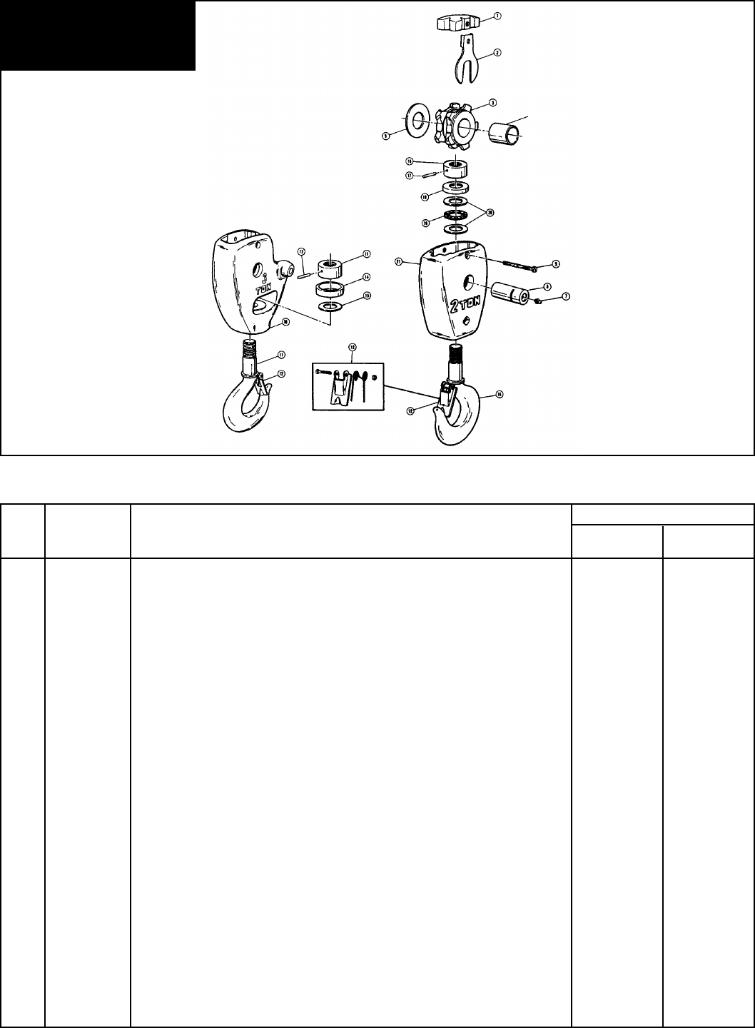
Page 33
Figure 8-5. 2 & 3 TON LOWER BLOCK ASSEMBLIES
To enable us to expedite your
parts order, always give Model
and Catalog Number of Hoist.
(See nameplate.)
12439
Quantity Required
Ref. Part
No. Number Description 2 Ton 3 Ton
BH-2219 Block Assembly - Lower Complete 1 -
BH-5038 Block Assembly - Lower Complete Plated 1 -
BH-2218 Block Assembly - Lower Complete - 1
BH-5039 Block Assembly - Lower Complete Plated - 1
1 BH-2202 Guide - Center 1 1
BH-5042 Guide - Center Anodized 1 1
2 BH-2203 Lock - Sprocket Pin 1 1
3 BH-2204 Sprocket - Coil Chain 1 1
4 BH-2205 Bushing - Sprocket 1 1
5 BH-2206 Screw - Fillister Head, Self locking 1 1
6 BH-2207 Pin - Sprocket 1 1
7 BH-2208 Fitting - Hydraulic Drive 1 1
9 BH-2210 Washer, Thrust 1 1
10 BH-2211 Body Assembly - Lower Block - 1
BH-5040 Body Assembly - Lower Block Anodized - 1
11 BH-2212 Hook/Latch & Nut (Includes Items 12, 13 & 15) - 1
BH-5044 Hook/Latch & Nut (Includes Items 12, 13 & 15) Plated - 1
12 BH-2213 Latch Kit, Hook 1 -
BH-2214 Latch Kit, Hook - 1
13 BH-2215 Pin, Grooved - 1
14 BH-2216 Shroud -1
15 BH-2217 Washer, Thrust - 1
16 BH-2220 Hook/Latch & Nut (Includes Items 12 & 17) 1 -
BH-5043 Hook/Latch & Nut (Includes Items 12 & 17) Plated 1 -
17 BH-2221 Pin, Grooved 1 -
18 BH-2222 Shield, Bearing 1 -
19 BH-2223 Bearing Assembly - Needle, Thrust 1 -
20 BH-2224 Washer, Thrust 2 -
21 BH-2225 Body - Lower Block 1 -
BH-5041 Body - Lower Block Anodized 1 -

Page 34
Ref. Part Qty.
No. Number Description Req’d
1 BAH-5100 Supply Head 1
2* BAH-5101 Valve Support 2
3* BAH-5102 Valve Guide Assembly 2
4 BAH-5103 Muffling Material 6
5 BAH-5104 Screen - Exhaust Valve 2
6 BAH-5105 Ring - Internal Retaining 2
7 BAH-5106 Screw - Self Tapping 2
8 BAH-5107 Adaptor Fitting 3
9 BAH-5108 Cap Screw - Hex Head 2
10 BAH-5109 Elbow - Reducing 1
11 BAH-5110 Nipple - Close Pipe 1
12 BAH-5111 Coupling Assembly 1
13 BAH-5112 Cap Screw - Hex Socket 2
14 BAH-5113 Lockwasher - Spring Type 2
15 BAH-5114 Gasket - Supply Head 1
16 BAH-5115 Muffler Body 1
17 BAH-5117 Gasket - Muffler 1
18 BAH-5117 Screen - Muffler 1
19 BAH-5118 Screw - Drive 2
20 BAH-5119 Muffler Cover 1
21 BAH-5120 Gasket - Muffler Cover 1
22 BAH-5121 Screw - Pan head 2
23* BAH-5123 Stem - Valve 2
24* BAH-5124 Spring - Valve 2
25* BAH-5125 Sleeve - Valve 2
26 BAH-5126 Screen - Muffler 1
Figure 8-6. SUPPLY HEAD AND MUFFLER PARTS
To enable us to expedite your
parts order, always give Model
and Catalog Number of Hoist.
(See nameplate.)
12441A
* Reference Numbers 23, 24, and 25 replace Reference Numbers 2 and 3 used on earlier model hoists.
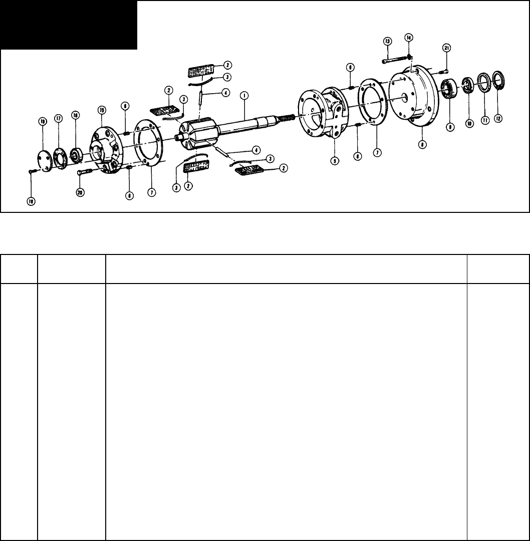
Page 35
Ref. Part Qty.
No. Number Description Req’d
BAH-5200 Air Motor Assembly 1
1 BAH-5201 Rotor and Shaft Assembly 1
2 BAH-5202 Vane 8
3 BAH-5203 Spring - Vane 8
4 BAH-5204 Push Pin 4
5 BAH-5205 Body -Air Motor 1
6 BAH-5206 Pin - Dowel 4
7 BAH-5207 Gasket - Body 2
8 BAH-5208 End Plate - Drive End 1
9 BAH-5209 Bearing - Drive End 1
10 BAH-5210 Shaft Seal 1
11 BAH-5211 Seal Adaptor 1
12 BAH-5212 Ring - Retaining 1
13 BAH-5213 Cap Screw - Hex Socket 4
14 BAH-5214 Lockwasher - Spring Type 4
15 BAH-5215 End Plate - Dead End 1
16 BAH-5216 Bearing - Dead End 1
17 BAH-5217 Gasket - End Cap 1
18 BAH-5218 End Cap - Dead End 1
BAH-5219 End Plate Puller Tool (Not Shown) -
19 BAH-5220 Screw 3
20 BAH-5221 Screw 6
21 BAH-5222 Screw 6
Figure 8-7. AIR MOTOR PARTS
To enable us to expedite your
parts order, always give Model
and Catalog Number of Hoist.
(See nameplate.)
12442A

Page 36
Ref. Part Qty.
No. Number Description Req’d
1 BAH-5300 Cap Screw - Hex Head 1
2 BAH-5301 Washer 1
3 BAH-5302 Thimble - Wire Rope 1
4 BAH-5303 Set Screw 1
5 BAH-5304 Clip - Wire rope 2
6 BAH-5305 Cable - Strain Relief (Specify length Required)
7 ft. for 10 ft. Lift 1
12 ft. for 15 ft. Lift 1
17 ft. for 20 ft. Lift 1
7 BAH-5306 Sleeve - Pressed 1
8 Hose Assembly - Down
BAH-5307 For 10 ft. Lift 1
BAH-5308 For 15 ft. Lift 1
BAH-5309 For 20 ft. Lift 1
9 Hose Assembly - UP
BAH-5310 For 10 ft. Lift 1
BAH-5311 For 15 ft. Lift 1
BAH-5312 For 20 ft. Lift 1
10 Hose Assembly - Supply
BAH-5313 For 10 ft. Lift 1
BAH-5314 For 15 ft. Lift 1
BAH-5315 For 20 ft. Lift 1
11 BAH-5316 Tie - Cable 2
12 BAH-5317 Adaptor Fitting 3
13 BAH-5318 Pendant Throttle Handle Assembly - Complete (Includes Ref. Nos. 14 through 20
plus handle) 1
14 BAH-5319 Pin - Throttle Lever 1
15 BAH-5320 Throttle Lever 2
16 BAH-5321 Valve - Throttle 2
17 BAH-5322 Ring - Throttle Valve Seal 4
Figure 8-8. PENDANT THROTTLE CONTROL PARTS
To enable us to expedite your
parts order, always give Model
and Catalog Number of Hoist.
(See nameplate.)
12443

Page 37
Fig. Ref. Part Corrosion Resistant Spark Resistant
No. No. Number Description 1 Ton 2 Ton 3 Ton ½ Ton 1 Ton 2 Ton
8-1 1 BAH-5400 Hook Assembly-Upper with Latch - - 1 - -
11 BAH-5401 Cover - Counterweighted - - - 1 - -
BAH-5402 Cover - Counterweighted - - - - 1 -
BAH-5403 Cover - Counterweighted - ----1
24 BAH-5430 Guide Assembly - Coil Load Chain - - - 1 1 1
25 BAH-5404 Chain Assembly - Coil, Load 1 ---- -
BAH-5404 Chain Assembly - Coil, Load - - - 1 - -
30 BAH-5406 Block Assembly - Lower - - - 1 - -
32 BAH-5407 Body - Lower Block - - - 1 - -
33 BAH-5408 Hook, Nut and Latch Assembly
- Lower Block - - - 1 - -
34 BAH-5409 Latch Kit - Hook, Lower - - - 1 - -
51 BAH-5410 Latch Kit - Hook Upper - - - 1 - -
8-2 2 BAH-5411 Hook Assembly-Upper with Latch - - - - 1 -
18 BAH-5412 Chain Assembly - Coil, Load - 1 - - - -
BAH-5413 Chain Assembly - Coil, Load - - - - 1 -
20 BAH-5414 Latch Kit - Hook, Upper - - - - 1 -
8-3 5 BAH-5415 Hook Assembly - Upper with Latch - - - - 1
18 BAH-5417 Chain Assembly - Coil, Load - - 1 - - -
BAH-5418 Chain Assembly - Coil, Load - ----1
8-4 11 BAH-5429* Gear & Clutch Assembly
- Load Brake - - - 1 1 1
35 BAH-5419 Sprocket - Coil Chain - - - 1 1 1
8-5 - BAH-5420 Block Assembly - Lower Complete - - - - 1 -
- BAH-5421 Block Assembly - Lower Complete - ----1
10 BAH-5422 Body Assembly - Lower Block - ----1
11 BAH-5423 Hook/Latch & Nut - ----1
12 BAH-5424 Latch Kit - Hook, Lower - - - - 1 -
16 BAH-5426 Hook/Latch & Nut - - - - 1 -
21 BAH-5427 Body Assembly - Lower Block - - - - 1
Figure 8-9. SPECIAL PARTS TABLE - CORROSION RESISTANT AND SPARK RESISTANT MODELS


Notes

A. Seller warrants that its products and parts, when shipped, and its
work (including installation, construction and start-up), when
performed, will meet applicable specifications, will be of good quality
and will be free from defects in material and workmanship. All claims
for defective products or parts under this warranty must be made in
writing immediately upon discovery and in any event, within one (1)
year from shipment of the applicable item unless Seller specifically
assumes installation, construction or start-up responsibility. All claims
for defective products or parts when Seller specifically assumes
installation, construction or start-up responsibility and all claims for
defective work must be made in writing immediately upon discovery
and in any event, within one (1) year from completion of the applicable
work by Seller, provided; however, all claims for defective products
and parts made in writing no later than eighteen (18) months after
shipment. Defective items must be held for Seller’s inspection and
returned to the original f.o.b. point upon request. THE ‘FOREGOING
IS EXPRESSLY IN LIEU OF ALL OTHER WARRANTIES
WHATSOEVER, EXPRESS, IMPLIED AND STATUTORY,
INCLUDING, WITHOUT LIMITATION, THE IMPLIED WARRANTIES
OF MERCHANTABILITY AND FITNESS.
WARRANTY
WARRANTY AND LIMITATION OF REMEDY AND LIABILITY
B. Upon Buyer’s submission of a claim as provided above and its
substantiation, Seller shall at its option either (i) repair or replace its
product, part or work at either the original f.o.b. point of delivery or at
Seller’s authorized service station nearest Buyer or (ii) refund an
equitable portion of the purchase price.
C. This warranty is contingent upon Buyer’s proper maintenance and
care of Seller’s products, and does not extend to normal wear and
tear. Seller reserves the right to void warranty in event of Buyer’s
use of inappropriate materials in the course of repair or maintenance,
or if Seller’s products have been dismantled prior to submission to
Seller for warranty inspection.
D. The foregoing is Seller’s only obligation and Buyer’s exclusive
remedy for breach of warranty and is Buyer’s exclusive remedy
hereunder by way of breach of contract, tort, strict liability or otherwise.
In no event shall Buyer be entitled to or Seller liable for incidental or
consequential damages. Any action for breach of this warranty must
be commenced within one (1) year after the cause of action has
accrued.
Recommended Spare Parts
for Your YALE KAL2 Air Hoist
Certain parts of your hoist will, in time, require replacement under normal wear conditions.
It is suggested that the following parts be purchased for your hoist as spares for future use.
One Set of Brake Discs
One Set of Gaskets
One Set of Oil Seals and "O" Ring
One Set of Motor Vanes
One Set of Motor Springs
One Set of Motor Pins
Note: When ordering parts always furnish Model Number of Trolley.
Parts for your trolley are available from your local authorized YALE repair station.
For the location of your nearest repair station, write:
Distributed by Tri-State Equipment Company Inc.
www.tsoverheadcrane.com
Tel: (314) 869-7200
Distributed by Tri-
State Equipment Company Inc.
www.tsoverheadcrane.com
Tel: (314) 869-7200
